R E S E A R C H
Open Access
Hitch Hiker 2.0: a binding model with
flexible data aggregation for the
Internet-of-Things
Gowri Sankar Ramachandran
1*, José Proença
1,3, Wilfried Daniels
1, Mario Pickavet
2,
Dimitri Staessens
2, Christophe Huygens
1, Wouter Joosen
1and Danny Hughes
1Abstract
Wireless communication plays a critical role in determining the lifetime of Internet-of-Things (IoT) systems. Data aggregation approaches have been widely used to enhance the performance of IoT applications. Such approaches reduce the number of packets that are transmitted by combining multiple packets into one transmission unit, thereby minimising energy consumption, collisions and congestion. However, current data aggregation schemes restrict developers to a specific network structure or cannot handle multi-hop data aggregation. In this paper, we propose Hitch Hiker 2.0, a component binding model that provides support for multi-hop data aggregation. Hitch Hiker uses component meta-data to discover remote component bindings and to construct a multi-hop overlay network within the free payload space of existing traffic flows. Hitch Hiker 2.0 provides end-to-end routing of low-priority traffic while using only a small fraction of the energy of standard communication. This paper extends upon our previous work by incorporating new mechanisms for decentralised route discovery and providing additional application case studies and evaluation. We have developed a prototype implementation of Hitch Hiker for the LooCI component model. Our evaluation shows that Hitch Hiker consumes minimal resources and that using Hitch Hiker to deliver low-priority traffic reduces energy consumption by up to 32 %.
Keywords: Data aggregation, Binding model, Component-based software engineering, Low energy, Component meta data, Middleware, IoT
1 Introduction
Internet-of-Things (IoT) devices must operate for long periods on limited power supplies and research has shown that wireless communication is the primary source of energy consumption in IoT devices [1]. The life-time of IoT applications can therefore be increased by minimising radio communication.Data aggregation has been widely applied to tackle this problem [2–4]. Data aggregation is a technique in which multiple messages are combined in to a single datagram, thus reducing radio transmissions and hence the energy consump-tion of IoT devices. Furthermore in CSMA networks, less frequent transmissions result in fewer collisions and
*Correspondence: [email protected] 1iMinds-DistriNet, KU Leuven, 3001 Leuven, Belgium
Full list of author information is available at the end of the article
therefore retransmissions. This significantly improves the performance of IoT devices.
This paper focuses on lossless data aggregation, through the efficient merging of application traffic flows, rather than algebraic in-network aggregation. Contem-porary approaches to lossless data aggregation may be classified as either application dependent or applica-tion independent [5]. Application dependent approaches [6–8] support the creation of optimal network-wide data aggregation structures, but restrict the topology of the dis-tributed application. In contrast, application independent approaches [6, 9] embed generic aggregation functional-ity in the underlying network stack, but do not consider the application, and therefore do not achieve optimal performance.
A new approach is needed that allows developers to build custom application communication structures, while providing support for efficient data aggregation. To
tackle this problem, this paper introduces Hitch Hiker,
a lightweight remote binding model with support for
multi-hop data aggregation. Hitch Hiker uses the same semantics to configure aggregate data flows as standard bindings, reducing development overhead.
A component binding model specifies how remote soft-ware components communicate. Well known examples include Remote Procedure Call (RPC) [10, 11] and event-based communication [12, 13]. Hitch Hiker extends bind-ing models to distbind-inguish betweenhigh-andlow-priority bindings. Low-priority bindings use a multi-hop data aggregation overlay network, built from the free payload space of high-priority bindings, and therefore avoid addi-tional radio transmissions between remote components. Using component meta-data, Hitch Hiker constructs a multi-hop data aggregation overlay. The Hitch Hiker binding model allows developers to specifyhigh-priority remote bindings that generate radio transmissions, or low-priorityremote bindings which communicate exclusively using the data aggregation overlay and therefore result in no additional transmissions. By routing low-priority traffic over this data aggregation overlay, Hitch Hiker significantly reduces energy consumption. Furthermore, low-priority bindings provide developers with an elegant way of configuring data aggregation. To the best of our knowledge, Hitch Hiker is the first binding model that provides built-in support for data aggregation.
Our previous short paper on this topic [14] introduced a centralised version of Hitch Hiker, in which multi-hop data aggregation is managed by a single network entity. This paper extends Hitch Hiker [14] by allowing the user to choose between centralised Hitch Hiker or Ad-hoc Hitch Hiker. The Ad-hoc variant of Hitch Hiker eliminates the dependency on the network manager, thereby allowing Hitch Hiker to operate in a fully distributed manner. This allows for the use of multiple meta-managers as supported by LooCI. Ad-hoc Hitch Hiker uses an approach inspired by the well-known Adhoc On-Demand Distance Vector (AODV) [15] routing approach on top of the aggregation overlay for discovering data aggregation routes.
A prototype of Hitch Hiker has been implemented for the LooCI component model [13] running on the Con-tiki OS [16] and for the OMNeT++ [17] simulator. Our evaluation using two real-world case studies show that: (i.) the resource consumption of Hitch Hiker is minimal and (ii.) by using Hitch Hiker to transmit low-priority traffic, energy consumption is significantly reduced.
The remainder of this paper is structured as follows. Section 2 reviews related work. Section 3 introduces the Hitch Hiker-2.0 binding model. Section 4 explains the route discovery process of infrastructure Hitch Hiker. The ad-hoc mode of Hitch Hiker is explained in Section 5. Section 6 discusses the route maintenance schemes of Hitch Hiker. Section 7 describes our case study
applications. Section 8 introduces and evaluates proto-type implementations of Hitch Hiker-2.0. Finally Section 9 concludes and discusses directions for future work.
2 Related work
We draw upon two streams of prior work. Section 2.1 discusses related work in the area of data aggregation. Section 2.2 discusses contemporary component and bind-ing models. We then discuss opportunities for applybind-ing data aggregation in component bindings in Section 2.3.
2.1 Data aggregation schemes
He et al. [5] describe two classes of data aggrega-tion approach: Applicaaggrega-tion Dependent Data Aggregaaggrega-tion (ADDA), which requires knowledge of application-level traffic flows and Application Independent Data Aggre-gation (AIDA) which performs aggreAggre-gation in a generic fashion without application-specific information. We dis-cuss both classes of aggregation in Sections 2.1.1 and 2.1.2, respectively.
2.1.1 Application dependent data aggregation
ADDA approaches use network-wide application infor-mation to optimise the manner in which inforinfor-mation is collected and routed across the network. These efforts focus upon the network and application layers of the communication stack.
At the Network Layer, Intanagonwiwat et al. intro-duce Directed Diffusion [6], which provides data-centric routing, in-network caching and aggregation. To realise these features, Directed Diffusion provides a common data representation. Entities that request data register an interest in a particular data type at a certain net-work location, which causes a conceptualgradientto be established between sources and requesters, data is then drawndown these gradients from sources to requesters. As data travels down these routes, it is aggregated and cached.
depth in the network. LAG uses learning automata to update the route as the energy levels of the nodes change during run-time.
Network-flow based data aggregation protocols [21, 22] take an orthogonal approach, modelling the sensor net-work as a graph and, based upon application-level traffic flows, calculating and configuring an optimal aggrega-tion structure. Kapakis et al. [21] contribute MDLA, a network-flow based approach to achieving maximum network lifetime using linear programming and con-straints. Xue et al. [22] contribute MaxLife, a commod-ities-inspired algorithm, wherein a commodity models the data that is generated by a sensor node and deliv-ered to a base station. MaxLife is capable of calculating optimal data aggregation structures and thereby extend-ing network lifetime. Voulkidis et al. [23] contribute a game-theoretic approach to reduce the number of trans-missions. This approach estimate the spatial correlation of the sensor data and optimises the transmissions based on the spatial relationship. Xiang et al. [24] contribute a data aggregation approach based on compressed sens-ing, which uses diffusion wavelets to account for the spatial and temporal correlations. Network-flow based approaches offer efficient calculation of an optimal data aggregation structure, for static networks where network-wide data flows are known, but these approaches are unsuitable for dynamic networks which support runtime reconfiguration.
From the above application dependent data aggregation approaches, it can be seen that contemporary approaches are either inherently static as in network flow models [6], or otherwise restrict developers to a single applica-tion interacapplica-tion model [7] or routing topology [21, 22]. In contrast, application-independent approaches provide a moregenericaggregation approach, discussed below in Section 2.1.2.
2.1.2 Application independent data aggregation
AIDA schemes provide a one size fits all approach to data aggregation that is independent of application require-ments. These approaches typically operate at the network and data link layer.
At theNetwork Layer, well known approaches to aggre-gation include the Shortest Path Tree (SPT), wherein a single, network-wide aggregation tree is centrally calcu-lated and configured and the Greedy Incremental Tree (GIT) which approximates a shortest path tree, but is constructed in an incremental and decentralised fash-ion [25]. However, these approaches are poorly suited to Wireless Sensor Networks (WSN) scenarios where energy resources are unevenly distributed. Aonishi et al. contribute Adaptive GIT [9] to address this problem. Intanagonwiwat et al. contribute the Centre at the Nearest Source (CNS) [6] scheme, wherein the responsibility for
data aggregation is assigned to the node which is a source of that data type and closest to the destination.
Leandro et al. [26] contribute DRINA, a lightweight and reliable routing approach for in-network aggrega-tion. DRINA follows a cluster-based approach and builds a shortest path tree to sink. Nodes in each cluster for-ward the sensed data to the cluster head, which then relays the data to the sink. This solution relies on a dedi-cated node to perform data aggregation, which means all nodes in the cluster must transmit the sensed data to the cluster head. Jongsoo et al. [27] propose Lump to per-form Quality-of-Service aware aggregation for heteroge-neous traffic. Lump prioritises packet based on the latency requirements. Lump maintains a queue for each next-hop address, where it stores the packets. Lump uses a periodic send-timer, which raises the priority level of the packets on each timer event. Whenever the priority is raised to the highest level, all packets in the queue are aggregated and transmitted.
At theData Link Layer, He et al. contribute AIDA [5], which takes advantage of queuing delay and the broad-cast nature of wireless media to implement application independent data aggregation. AIDA aggregates multiple packets into single frames prior to transmission, result-ing in significant savresult-ings in terms of energy and latency. While AIDA uses data from the network layer, it treats the application layer as a black box and therefore cannot exploit patterns in application traffic flows. Furthermore, as AIDA operates at the data link layer, it is unable to perform multi-hop data aggregation.
2.2 Remote component binding models
Hitch Hiker combines aggregation with a lightweight remote binding model. In this section, we review compo-nent binding models and discuss opportunities for aggre-gation. Contemporary remote binding models typically offer either event-based or Remote Procedure Call (RPC) semantics.
RPC-based binding modelsallow remote functionality to be called using the same semantics as local procedures, thus lowering the overhead on component developers. RPC-based models are request-reply and therefore bidi-rectional in nature. In the case of resource-rich sensing systems, Remote Method Invocation (RMI) [10] has been used to provide reliable RPC-based bindings for Java com-ponent models such as OSGi [28] and RUNES [29]. In a WSN context, May et al. [11] extend NesC [30] with sup-port for unicast and anycast RPC calls, wherein exactly one neighbouring node responds to the call. Where com-ponent models support remote reconfiguration, bindings may be modified at runtime.
scenarios, as they are lightweight and do not cause soft-ware modules to block while waiting for responses as in RPC. The Active Messages [12] protocol provides remote bindings for the NesC [30] component model. A unique reference to an application handler is embedded in each active message and is used to dispatch incoming messages to the appropriate handler component. As NesC does not allow for runtime reconfiguration, bindings are fixed at development time. The LooCI binding model [13] pro-vides unreliable event-based binding using a decentralised publish-subscribeevent buscommunication medium. In contrast to Active Messages, LooCI supports multi-model bindings allowing for the modelling of to-one, one-to-many, many-to-one and many-to-many relationships. Additionally, unlike Active Messages, LooCI bindings may be remotely modified at runtime in order to enact recon-figuration.
Considering opportunities for cross-layer optimisation, all of the binding models discussed above [10, 30] provide explicit meta-data that can be used to determine traf-fic flows and therefore optimise aggregation functionality. Despite this opportunity, current component models typ-ically treat the network layer and below as a black box, resulting in suboptimal communication.
2.3 Opportunities for data aggregation
There are a number of advantages to embedding data aggregation support in a component binding model:
Flexible Network Topologies:ADDA approaches to data aggregation such as TAG [7] and Directed Diffusion [6] enforce a single network topology, which may be subop-timal for some application scenarios. In contrast, compo-nents can be remotely bound together to form distributed component graphs with flexible network topologies.
Support for Multiple Applications: WSN are increas-ingly required to simultaneously support multiple applica-tions. Contemporary ADDA approaches are poorly suited to multi-application scenarios as they enforce a single routing structure across multiple applications with dif-ferent networking requirements. In contrast, component bindings can be used to create a specific network topology for each application.
Appropriate Separation of Concerns:ADDA approaches require that the lower layers of the network stack be con-cerned with application-level data flows [5]. This means that aggregation protocols must be updated whenever new data types are introduced. In contrast, components provide externally visible meta-data that describes data flows via bindings. This allows aggregation functionality to evolve along with the application components during software reconfiguration.
Application-Optimised Aggregation: AIDA approaches such as CNS [6] and AIDA [5] are unaware of application data flows and therefore would be expected to perform
sub-optimally in comparison to application dependent approaches. In contrast, component-binding meta-data provides a means to optimise generic aggregation func-tionality to suit a specific application.
By using component binding meta-data to build a multi-hop aggregation network, Hitch Hiker combines the key benefits of application dependent aggregation (i.e. an opti-mised aggregation approach) with those of application independent aggregation (i.e. flexible networking and a more appropriate separation of concerns). The following section describes the Hitch Hiker binding model.
3 The Hitch Hiker 2.0 binding model
Hitch Hiker 2.0 extends the previous version of Hitch Hiker, which is reported in [14]. In Hitch Hiker, the bind-ings are classified as either high or low priority bindbind-ings. This classification allows Hitch Hiker to support data aggregation by appending low-priority data in the over-lay network created using the unused payload space of high-priority transmissions. Hitch Hiker uses meta data provided by component bindings to create a multi-hop data aggregation overlay. To support end-to-end rout-ing of low-priority traffic, Hitch Hiker performs route discovery on multi-hop overlay network using a central meta-manager.
Hitch Hiker 2.0 expands the previous version of Hitch Hiker [14] with Ad-hoc Hitch Hiker, which does not rely on central meta-manager to discover the data aggregation overlay. Ad-hoc Hitch Hiker uses an approach inspired by AODV for route discovery.
This section describes the design of the Hitch Hiker binding model and its associated network stack. Section 3.1 provide background on LooCI, which is extended with Hitch Hiker. Section 3.2 introduces pri-oritised bindings. Section 3.3 describes how route infor-mation is extracted from bindings. Sections 3.4 and 3.5 describe the Hitch Hiker network stack.
3.1 The loosely-coupled component infrastructure
The Loosely-coupled Component Infrastructure (LooCI) [13] is a platform-independent component model and supporting middleware targeting networked embedded systems. The LooCI middleware is open-source and ports are available for embedded operating systems such as Contiki [16], Squawk [31] and Android. LooCI is a repre-sentative example of a runtime reconfigurable component model for the IoT, with which we have extensive expe-rience. Hitch Hiker extends the basic LooCI component model to support priority-based multi-hop data aggrega-tion. The remainder of this subsection provides a basic overview of the relevant features of LooCI.
creating an instance of the basic LooCI meta-model, described in [13], using a simple component declaration and communication API consisting of required and provided interfaces. LooCI is language-agnostic and components may be implemented in C or Java, allowing developers to exploit language-specific features while pro-viding standardised encapsulation, discovery and lifecycle management. All messages that travel across component interfaces are hierarchically typed as described in [32]. Components may also declare properties that allow for inspection and customisation of component behaviour through externally accessible name/value tuples.
Communication All LooCI components communicate over a fully distributed ‘event bus’ spanning the entire network. The event-bus is an asynchronous event-based communication medium that follows a decentralised topic-based publish-subscribe model. Local and remote bindings are established by creating new subscription relationships, supporting one-to-one, many-to-one, and one-to-many bindings (as specified in [13]). Hitch Hiker extends the binding model of LooCI with support for data aggregation. Hitch Hiker classifies LooCI bindings as high-priority and low-priority, and this classifica-tion allows Hitch Hiker to support data aggregaclassifica-tion by appending low-priority data in the overlay network cre-ated using the unused payload space of high-priority transmissions.
Reconfiguration LooCI components are connected to the middleware runtime installed on every device. Each component declares its human-readable name, its required interfaces (i.e. services) and provided interfaces (i.e. dependencies). A reconfiguration engine manages the basic meta-model and supports reflective operations using both local or remote API calls.
Meta Manager LooCI applications are deployed, inspected, and configured by manager nodes. In prin-ciple, any LooCI node may serve as a manager and a network may have multiple managers. The manager inter-acts with the nodes by using the reflection API to inspect and reconfigure LooCI’s meta-model. Hitch Hiker uses a single meta manager in infrastructure mode for the creation of data aggregation overlay, which is a major
restriction. Hitch Hiker 2.0 supports Ad-hoc Hitch Hiker, which operates with either multiple or no manager at all.
3.2 Prioritised bindings
Figure 1 shows a small part of the smart building case study, evaluated later in this paper. Here, a temperature component, deployed on sensor nodeN1, samples tem-perature data once every 30 s and sends the data to the comfort level component. The comfort level compo-nent onN2, analyses sensor data, and sends the result to a manager located on N3 every 30 s. These three com-ponents communicate via standard bindings, depicted
as . For the remainder of this paper, we refer the
standard bindings as high-priority bindings. LooCI pro-videsbindToandbindFromcalls to create high-priority bindings.
Hitch Hiker introduces the concept oflow-priority
bind-ings, depicted as in Fig. 1. Low-priority bindings
are used by non-critical applications, the definition of which is left to the developer. In principle, the developer should use low-priority bindings for traffic that can toler-ate long ltoler-atencies. Hitch Hiker providesbindHHToand bindHHFromcalls to create low-priority bindings. In our example, a node monitor component deployed onN1is connected to a node alert component deployed onN3via a low-priority binding. The use of a low-priority binding indicates that the developer is willing to trade commu-nication performance for energy efficiency. Low-priority bindings are realised in Hitch Hiker by routing messages via the data aggregation overlay network, referred to as Hitch Hiker network.
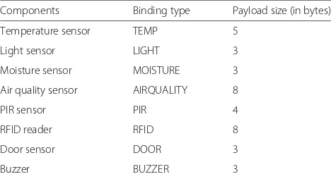
High-Priority Bindings Hitch Hiker extends the event-based LooCI binding model described in Section 3.1. LooCI bindings are: event-based, unidirectional, and unreliable. Conceptually, a LooCI binding is a connec-tion between a source and a destinaconnec-tion component, with an associated data type and a reference to the network linkthat connects the nodes hosting the two components. Table 1 shows the list of well-known LooCI binding types and their payload sizes.
Definition 1 (Binding).A binding is a tuple b =
Cs,Cd,Type,Link, where Csis the source component, Cd is the destination component, Type is the type of the events sent through the binding, and Link is the remote connection
Table 1List of LooCI binding types and their payload sizes
Components Binding type Payload size (in bytes)
Temperature sensor TEMP 5
Light sensor LIGHT 3
Moisture sensor MOISTURE 3
Air quality sensor AIRQUALITY 8
PIR sensor PIR 4
RFID reader RFID 8
Door sensor DOOR 3
Buzzer BUZZER 3
between the nodes where the binding is deployed, defined below.
Definition 2(Remote Connection).A remote connec-tion is a tuple = Ns,Nd,MTU,Bw,D describing the communication channel between two network nodes, where Ns is the source node, Nd is the destination node, MTU is the maximum transmission unit between Nsand Nd, Bw is the bandwidth of the remote connection, and D is the expected delay of the remote connection.
A LooCI binding is realised as anoutgoing bindingentry on the sending node and anincoming bindingentry on the receiving node, which is established by issuingbindTo andbindFromcalls to the sender and receiver, respec-tively. These bindings are stored in abinding tablewhich is used to dispatch events. LooCI bindings are created at runtime after the deployment of the involved compo-nents. High-priority binding is mediated by the trans-mission of a event using the network stack of the host operating system.
The binding from the temperature component
is formally represented as Temperature,Comfort
Level,Temp,, where the associated remote connection = N1,N2, 127B, 250kbps, 0.1s.
Low-Priority Bindings Hitch Hiker introduces the concept of a low-priority binding, depicted as
in Fig. 1. In our example, a node monitor component
gathers the local node status and transmits this data
to a node alert component running on a server. We
selected node monitoring as an example of a low-priority application because this functionality is less important than the core WSN mission of gathering environmen-tal data and this application data can tolerate delay. However, it should be noted that developers are free to define which components are high-priority and low-priority in their application context. In our example (Fig. 1), the low priority binding that connects the node
monitor to the node alert component is formally rep-resented as Node Monitor,Node Alert,Status,status, where Statusis the event type containing node status information and status is the remote connection of the overlay network.
High-priority and low-priority bindings have an iden-tical set of artefacts: a source component, destination component, data type (Definition 1) and a remote connec-tion (Definiconnec-tion 2). Low-priority bindings are realised in LooCI by adding a separate set ofbinding tablesto each node.
The overlay routes necessary to support low-priority bindings are established reactively, as it required to sup-port low-priority bindings.
3.3 Component model probe extracts network data
The component modelprobeextracts data from the high-priority application to create the remote connections of the Hitch Hiker network. Itintercepts binding acknowledg-mentmessages containing the source componentCs, the source nodeNs, the destination nodeNd, and the bind-ing Type, and builds a remote connection for the Hitch Hiker network. Recall that a remote connection is for-mally a tuple Ns,Nd,MTU,Bw,D (Definition 2). The MTUis calculated based on the event type, which has an associated payload size, as shown in Table 1. Hitch Hiker extracts periodicity information by querying source com-ponents for theirperiodicityproperty using the standard LooCI API. Hitch Hiker distinguishes between periodic andnon-periodiccomponents: the former send values at a fixed rate (e.g., a temperature reading every 10 s), and the latter exhibit unpredictable behaviour (e.g., an alert generated when a window is opened).
Formally, we write(C)to denote the periodicity of a component C, defined below, which returns the special symbol⊥whenCis non-periodic.
(C)=
r ifCis periodic with rater;
⊥ otherwise.
Based upon the information intercepted in the binding acknowledgment—the source component Cs, the source nodeNs, the destination nodeNd, and the sourceType— and the periodicity(Cs), the probe calculates the remote connection for the Hitch Hiker network as follows.
1. Get the payload sizepsassociated with theType. 2. Get theMTU m of the remote connection between
the source (Ns) and destination (Nd).
3. Definehd to be the size of the headers used by the data-link, network and transport layers of the host protocol stack.
5. If(Cs)= ⊥then return the remote connectionNs, Nd,MTUHH,⊥,⊥, otherwise return the remote connection
Ns, Nd,MTUHH,MTUHH/(Cs),(Cs).
The component model probe reveals the remote con-nection between a source nodeNsand a destination node Ndwith a free payload space ofMTUHH. The probe also reveals the delay or the time-interval between two succes-sive transmissions as(Cs). For the example application shown in Fig. 1, the remote connection between nodeN1 andN2has a free payload space of 75B(excluding the tem-perature data and the overhead added by the other layers) with a delay of 30 s. This connection meta data is used for the configuration of Hiker routing protocol and it is discussed in Section 3.5.
3.4 Hitch medium access control (MAC) protocol
Figure 2 shows the Hitch Hiker network stack for a single embedded sensor node, with each layer numbered accord-ing to the 5-layer Tanenbaum reference model [33]. The Hitch Hiker protocol stack is composed of two protocols the Hitch MAC protocol and the Hiker routing proto-col. The former is described below and the latter in the following subsection.
Hitch is a virtual MAC protocol that manages and pro-vides access to the data aggregation overlay links. The Hitch MAC protocol is implemented as an independent
module, which allows Hitch to be used with third-party routing protocols at the aggregation overlay level.
Link Data Structures Hitch manages the set of virtual data links that are available on each sensor node. Each virtual data link maps to a remote overlay connection (Definition 2) that may be multi-hop and is composed of: a destination address, MTU, delay and bandwidth. Vir-tual links are created by theprobeand may be accessed through the HitchAPI, available online: http://goo.gl/ 7m2nwN.
A First In First Out (FIFO) queue is maintained per link where packets are buffered until they can be aggregated with high-priority traffic and dispatched. If the buffer reaches its capacity, the oldest frame in the queue is dis-carded, resulting in packet loss. Hitch is a best-effort protocol, which provides no reliability guarantees. Where reliability is required, it should be implemented by the upper layers.
Aggregation The Hitch protocol intercepts outgoing packets as they are passed to the host MAC protocol, and this protocol does not violate the security requirements of the host MAC protocol. If the virtual link queue asso-ciated with the destination of an intercepted packet is not empty, the available payload size is filled with pack-ets from the queue, until either the available payload space is exhausted or the buffer is empty. The modified
packet is then returned to the host MAC protocol to be transmitted.
Disaggregation The Hitch protocol intercepts incom-ing frames in the host MAC protocol, and disaggre-gates all encapsulated Hitch packets. The disaggregated packets are then passed to the network layer, while the original frame is passed back to the host data link pro-tocol. And, it operates within boundary of the host MAC protocol.
3.5 Hiker network protocol
Hiker is a multi-hop routing protocol that operates effi-ciently with the Hitch data link protocol.
Route Data Structures Hiker maintains a minimalist routing table on each node. This routing table begins empty, and routes are reactively configured by the net-work manager to support low-priority bindings. Each route is comprised of aremote destination, thevirtual link that represents the next hop on the route to this address
and a route-MTU which denotes the maximum packet
size that can traverse the complete route.
Routing When an incoming Hiker packet is received, the destination field of the packet is checked. If the destination is the local sensor node, it is passed to the transport layer. If the destination matches a known route, it is transmitted on the appropriate link using the transmit(frame,link)method of Hitch. If no route is known, the packet is discarded. Sections 4 and 5 explains the route discovery process of Hitch Hiker in infrastructure and ad-hoc mode, respectively.
Definition 3(Route).A route is a multi-hop remote con-nection (Definition 2) obtained by composing a non-empty sequence of remote connections, such that for every consec-utive remote connectionsandthe destination node of matches the source node of. Given a sequence of n remote connections:
Ns,1,Nd,1,MTU1,Bw1,D1,. . .,
Ns,n,Nd,n,MTUn,Bwn,Dn
its composition yields the route Ns,Nd,MTU,Bw,D, where
Ns=Ns,1 Nd=Nd,n
MTU=minni=1MTUi
Bw=minni=1Bwi D=
n i=1Di.
Hiker Packet Encapsulation Figure 3 shows a host packet that is aggregated with multiple Hitch Hiker (HH) packets. Each encapsulated HH packet has a 2a+1 byte header, whereais the length of a network address. One additional byte is used to represent the length of the pay-load that follows. We use 6LowPAN IPv6 address shorten-ing [34], resultshorten-ing in 2Baddresses in our case-studies.
4 Infrastructure Hitch Hiker
Ininfrastructure mode, Hiker assumes that a single LooCI network manager is running for the entire network, as shown in Fig. 2. This network manager enacts all manage-ment and reconfiguration. This information is exploited to create the data aggregation overlay network as follows:
1. Overlay links are discovered based upon extended binding acknowledgements. This information is provided by the component model probe as described in Section 3.3.
2. The network manager assembles discovered overlay links to form a network graph, wherein each link is labelled with its associated delay, MTU and bandwidth.
3. When the user requests the establishment of a low-priority bindingb :
(a) The graph is pruned to remove all links which have an insufficient MTU to support the specified data type.
(b) The Dijkstra algorithm is used to calculate the shortest path between the source and destination, using either delay or bandwidth as the link cost. Our evaluation uses delay as the link cost.
(c) The network manager configures theshortest path overlay route, or responds with an exception where no overlay route is possible. (d) Finally, the network manager configures the
route required by the low-priority bindingb, by sending route-creation messages to all involved nodes.
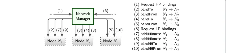
Figure 4 shows the networked interactions that are required to create both the high-priority and low-priority bindings for the running example shown in Fig. 1. In the interests of clarity and brevity, binding and route data shows only the network end-points.
Steps(1)–(5) The network manager receives a request to establish high-priority bindings to connect the Tempera-ture,Comfort Level, andManagercomponents. The net-work manager then enacts this request by issuing standard
LooCIbindToandbindFromcommands that establish
the required binding table entries. The associated binding acknowledgements inform the network manager of newly available overlay routes.
Steps(6)–(8) The network manager receives a request to establish a low-priority binding to connect theNode Monitorand theNode Alertcomponents. To support this binding, Hitch Hiker configures an overlayroutebetween the nodesN1andN3(Definition 3).
Steps(9)–(10) The network manager establishes the low-priority binding by issuing the required bindHHToand bindHHFrommethod calls, which establish the necessary entries in the Hitch Hiker wiring tables.
Since this mode of Hitch Hiker operate with a sin-gle network manager, the creation of Hitch Hiker bind-ings require binding meta data from the entire appli-cation network. In principle, any Hitch Hiker node in the network can create or remove bindings. In order to increase the flexibility of Hitch Hiker and to allow Hitch Hiker to operate with either multiple managers or no managers, we extend Hitch Hiker with support for decentralised route discovery, which is explained in Section 5.
5 Ad-hoc Hitch Hiker
In ad-hoc mode, Hiker routes are discovered in a fully decentralised manner. This allows Hiker to operate in networks with multiple managers or no managers at all, as shown in Fig. 2. The binding request can come from any node in the application network, and the Hiker of the source node self-discovers a overlay route, unlike
Infrastructure Hitch Hiker. To realise this, Hiker reimag-ines the well-known Ad-hoc On-Demand Distance Vector (AODV) routing approach [15]. To find overlay routes on top of bindings as opposed to at the network layer. In this mode, Hiker discovers the route as follows:
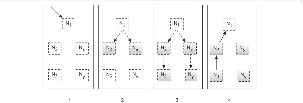
1. When the user requests the establishment of a low-priority bindingb, a route-discovery message is flooded across the data aggregation overlay as shown in Fig. 5.
2. The source node broadcasts a discovery message containing the destination address, required MTU, a sequence number and a Time to Live (TTL) on all links provided by the Hitch MAC protocol, as indicated in Fig. 5. And, the source node waits for NET_TRAVERSAL_TIME seconds for route-creation message. If the route-route-creation message is not received within NET_TRAVERSAL_TIME, then the source node notifies the developer that there is no route between the source and destination, and the low-priority binding is not accepted. Section 6 explains the error handling schemes of Hitch Hiker. 3. All nodes receiving a route-discovery message
decrement the TTL, add the sequence number and source link to their cache and re-broadcast the discovery message, discarding the message when the TTL reaches zero, or the available MTU is
insufficient, or if the sequence number was previously observed.
4. When the destination node receives the
route-discovery message as presented in Fig. 5, it establishes a router by responding with a route-creation message as follows:
(a) The first route-discovery message received by the destination denotes the shortest path between the source and the destination nodes. The destination node forwards a route-creation message back to the link on which the discovery message was received. This message contains the matching sequence number and the address of the destination node.
(b) On receipt of a route-creation message, each intermediate node adds a routing table entry mapping the specified destination address to the link on which the route-creation message was received.
(c) Following the creation of a routing table entry, the intermediate node checks its cache and forwards the route creation message on the link via which the original route-discovery was received. Step 2 repeats until the route is fully established.
As can be seen from the process described above, in ad-hoc mode, Hitch Hiker requires no supporting infrastruc-ture. However, the use of flooding increases the overhead and latency of route discovery in comparison to infras-tructure mode. Figure 5 shows the networked interactions that are required to create low-priority bindings for the running example shown in Fig. 1 using AODV routing approach.
6 Route errors and maintenance
Whenever a user creates a Hitch Hiker binding as described in Section 3, route discovery executes as described in Sections 4 and 5. If a low priority route was successfully created, Hitch Hiker returns true together with the performance properties of the route as listed in Definition 3, i.e. route MTU, latency and band-width. If the route was not created, Hitch Hiker returns false and the performance properties of the best avail-able route, if one exists. Based upon this information, the developer may choose to (i.) abandon the binding, (ii.) modify the binding to work within available Hitch
Hiker network capacity or (iii.) establish a high-priority binding.
6.1 Impact of reconfiguration
Hitch Hiker-2.0 builds on top of LooCI component model, which provides support for run-time recon-figuration of application. Such run-time reconfigura-tions may result in deployment of new components or the removal of existing components. In addition, the reconfiguration may also change the existing bind-ings in the application network. These reconfigura-tions disrupts the existing data aggregation overlay and might invalidate the existing routes of low-priority bindings.
In infrastructure mode, when the manager receives a reconfiguration command that invalidates a route, it removes the old route and then execute the route discov-ery process to find a replacement route. If no replacement route exists, an exception is generated. In adhoc mode, a mote that receives a reconfiguration command, which impacts a Hitch Hiker route will flood a route-remove message with the sequence number of the matching route. All motes that receive this message will remove the route, causing the source node to re-run the route discovery process.
7 Case study applications
We validate the performance of Hitch Hiker-2.0 in two representative application scenarios that are realised using the LooCI component model and prioritised bindings. Section 7.1 describes a low data rate multi-hop static smart officesensor network, while Section 7.2 describes a high data rate one-hop mobile robot sensor network.
The mobile robot application provides the greatest oppor-tunities for data aggregation due to its high data rate and one-hop network structure, while the smart office application is more challenging. In reality, we expect the characteristics of most WSN applications to fall some-where between those of these two applications. The smart office and the mobile robots applications are overlaid with a non-critical node health monitoring application, which uses low-priority Hitch Hiker bindings, described in Section 7.3.
7.1 Smart office application
The smart office application aims to ensure employee comfort, while reducing energy consumption by sensing environmental conditions and controlling relevant appli-ances. Sensor nodes (N2,N3andN4) monitor: tempera-ture, light and whether the window is open or closed every 30 s. This sensor data is transmitted to a comfort level component running on the cluster-head node (N1) which aggregates the sensor information and forwards the aggre-gated data to a manager component running on a server (N0), once every 30 s. Based upon the observed sensor data and configured comfort levels, a management com-ponent running on the server (N0) issues commands to a control component running on the cluster-heads (N1), which then activate or deactivate relay switches running on nodesN2toN4that control: lighting, ventilation and an audio alarm, which indicates that the window should be closed. The smart office application is realised using high-priority (i.e. standard) LooCI bindings. The payload size of all sensor data is4 bytes, the payload size of aggre-gated data is12 bytesand the payload size of relay control commands is4 bytes.
Figure 6 shows the application composition and all rel-evant binding and properties information. In terms of network topology, the scenario is comprised of 25 offices.
Each office contains three sensor nodes, and a cluster-head node. Sensor nodes communicate with cluster cluster-heads, which in turn communicate with a single server for man-agement of comfort level. This approximates a 101-node tree topology rooted at the server.
7.2 Mobile robot application
Themobile robotapplication coordinates a set of mobile robots to detect chemical spills. Each robot (N1toN100) runs a chemical sensor and a location sensor which sam-ple every 10 s and transmit the data to a coordination component running on the server (N0). The coordination component then calculates a set of navigation instructions every 10 s and transmits these to the navigation com-ponent running on each mobile robot (N1toN100). The mobile robot application is realised using standard LooCI bindings. The payload size of location data is6 bytes, the payload size of chemical sensor data is4 bytes and the payload size of navigation commands is5 bytes. Figure 6 shows the application composition and all relevant bind-ing and properties data. In terms of network topology, the scenario contains 100 mobile robots, all of which communicate directly with the coordinating server. This approximates a 101-node star topology.
7.3 Node health monitoring application
The node health monitoring application [35] is a low-priority application, inspired from real world deploy-ments such as Great Duck Island [36]. We consider it low-priority because it adds value, but (i.) the data is not critical and (ii.) it should not reduce the lifetime of the base application. This component monitors bat-tery level, memory use and the radio link quality. The application consists of a health monitor component that runs on all sensor nodes (N1 to Nn) and sends node health information to an alert component running on
the server node (N0). Node health monitoring is over-laid on the smart building and mobile robot application using low-priority bindings. The payload size of node health monitor data is 18B. The composition is shown in Fig. 6.
8 Implementation and evaluation
We have developed prototypes of Hitch Hiker-2.0 for the
OMNeT++ simulator [17] and the Zigduino mote [37].
Simulation is used to study the performance of the three case-study applications described in Section 7. The Zig-duino implementation validates node-local memory and energy characteristics for a concrete hardware/software stack.
OMNeT++settings:The physical layer is a CC2420 IEEE 802.15.4 radio [38]. We use B-MAC [39] as a representa-tive Low Power Listening (LPL) protocol. Simulation set-tings are based on prior experiments by Polastre et al. [39]. Table 2 shows the configuration settings of OMNeT++.
Zigduino configuration: Zigduino is an
Arduino-compatible mote based on the ATmega128RFA1 [40],
which offers a 16MHz MCU, 16KB of RAM, 128KB of
Flash and an IEEE 802.15.4 radio. We use ContikiOS v2.6, Contiki X-MAC (CX-MAC) [41] and LooCI v2.0 [13] extended with Hitch Hiker 2.0. The parameterisation of CX-MAC uses the default Contiki values. In the case of the mobile robot case-study the Zigduino is extended with a ShieldBot mobile robot base [42]. Table 2 shows the con-figuration settings of Zigduino. We compare Hitch Hiker against (i.) transmission of standard messages (referred as Standard binding) and (ii.) an optimally configured one-hop data aggregation scheme using an optimal aggre-gation buffer size of 3 (referred as One-hop aggreaggre-gation). Values reported below represent averages taken over one week.
All source code and simulation material are available at: http://goo.gl/7m2nwN.
8.1 OMNET++ simulation results
Latency Figure 7 shows the results of our latency simula-tion. Thex-axis shows the sampling frequency of the node health monitoring app, which was set to a consistent frac-tion of the case study applicafrac-tion frequency (from left to right from 10 to 50 % of the base app frequency). They -axis shows the latency of message transmission in seconds
Table 2Configuration of the OMNeT++simulation and the Zigduino implementation
Radio OMNet Zigduino MAC protocol OMNet Zigduino
Transmit current 17 mA 18.6 mA Check interval 0.1 s 0.125 s
Receive current 16.2 mA 16.6 mA Slot duration 1.0 s 2.0 s
Sleep current 0.02 mA 4.1 mA Queue length 10 15
for low-priority Hitch Hiker bindings, standard bindings and one-hop data aggregation.
As expected, the node health monitoring app exhibited a higher latency when using low-priority bindings than with standard bindings due to packets waiting for aggre-gation at each hop. However, the latency of low-priority bindings is lower than the one-hop aggregation scheme due to the exploitation of multi-hop routes. For themobile robot app(right of Fig. 7) the latency of Hitch Hiker falls as high-priority traffic is transmitted at a higher rate and thus, there are increased opportunities for aggregation.
Energy Figure 8 shows the results of our energy simula-tion. As with our latency experiments, the sampling fre-quency of the node health monitoring app was set to 10 to 50 % of the base application frequency. They-axis shows the power consumption low-priority Hitch Hiker bind-ings, standard bindings and one-hop data aggregation.
The results shown in Fig. 8 confirm the expected sav-ings when using Hitch Hiker to route low-priority traffic. Energy consumption is reduced by up to 15 % in the smart building scenario and up to 32 % in the mobile robot scenario compared to standard bindings. The energy con-sumption of Hitch Hiker is also lower than that of one-hop data aggregation. The greatest savings are achieved for the mobile robot application as more low-priority transmis-sions are aggregated.
8.2 Zigduino/Contiki implementation results
This section reports the performance timings of route configuration and message transmission as well as energy consumption and memory overhead for the Con-tiki/Zigduino implementation. Configuration timings are dependent upon the type of route being configured. We therefore report average timings based upon the smart building application, as this has the most complex routing structure.
Route Creation The Hitch Hiker 2.0 provides two approaches for route creation. Infrastructure Hitch Hiker requires approximately 86 ms to configure a single low-priority binding. Each additional hop that must be con-figured adds 30 ms to the configuration overhead. Route configuration is thus lightweight; creating all of the Hitch Hiker bindings required for the smart building takes less than 3 s. However, this generates three transmissions per Hitch Hiker binding, which costs 36.5mJ.
Fig. 7Latency of the health monitoring app. overlaid on the smart building (left) and mobile robot (right), with Hitch Hiker-2.0, one hop aggregation and standard bindings
to the configuration time, and the complete smart build-ing app takes less than an hour to configure. However, Ad-hoc Hitch Hiker generates only two transmissions per Hitch Hiker binding, which costs 23mJ– significantly less than infrastructure mode.
Message Transmission Enqueueing, dequeueing and encapsulating a single Hitch Hiker packet within a host frame requires on average of 12.27mJ, while a standard frame transmission using CX-MAC requires 21.41mJ, a saving of 57.4 % compared to standard transmission.
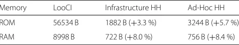
Memory Hitch Hiker introduces minimal memory over-head in comparison to the basic LooCI component model. As shown in Table 3, the implementation of Infrastruc-ture Hitch Hiker adds 3 % of ROM and 8 % of RAM to the LooCI component model. This implementation consists of component model probe along with Hitch and Hiker protocols, as presented in Section 3.
For Ad-hoc Hitch Hiker, the ROM and RAM overhead is approximately 6 and 8 % respectively. Ad-hoc Hitch Hiker consumes more memory than Infrastructure mode as each node must embed route discovery logic. Each routing table entry uses an additional 6Bof memory. We believe that this low overhead is reasonable in light of the energy savings reported in Section 8.1.
9 Conclusions and future work
This paper introduced Hitch Hiker 2.0, a novel remote binding model for IoT which supports prioritised bindings and multi-hop data aggregation. This prioritised binding model provides developers with a low-effort mechanism to manage data aggregation. Unlike prior work in the area of aggregation, Hitch Hiker uses component bind-ing meta-data to construct a multi-hop overlay network for data aggregation. Hitch Hiker provides support for routing on multi-hop overlay network. To the best of our knowledge, Hitch Hiker is both the firstgeneric and yet application aware data aggregation approach. Further-more, Hitch Hiker is the first remote binding model to provide built-in support for data aggregation.
Hitch Hiker 2.0 extended our previous work [14] and provides a decentralised routing approach. Hitch Hiker 2.0 allows the user to choose between centralised and decentralised routing approach, making it a flexible bind-ing model.
We have simulated the Hitch Hiker protocol in OMNeT++for two case-study application scenarios. Our results show that using Hitch Hiker to route low-priority traffic reduces energy consumption and, for applications with a high data rate, latency. We also implemented a prototype of Hitch Hiker for the LooCI component model running on the Contiki OS and the Zigduino mote. Our evaluation of the prototype implementa-tion shows that Hitch Hiker consumes minimal mem-ory, introduces limited overhead and that transmitting
Table 3Memory overhead of Hitch Hiker-2.0 (HH)
Memory LooCI Infrastructure HH Ad-Hoc HH
ROM 56534 B 1882 B (+3.3 %) 3244 B (+5.7 %)
RAM 8998 B 722 B (+8.0 %) 756 B (+8.4 %)
messages with Hitch Hiker consumes a small fraction of the energy that is required for a standard radio transmission.
Our future work will focus on four fronts: improving the performance of Hitch Hiker for non-periodic com-ponents, adding support for virtual circuits, extending Hitch Hiker to support variable component payloads and realising a RPC version of the Hitch Hiker binding model. Non-periodic components:The current design of Hitch Hiker tends to avoid aggregation with non-periodic bind-ings, where the source component not specify the rate property, due to the unpredictability performance of those links. This is a potential source of inefficiency in cases where non-periodic components transmit frequently. We plan to address this inefficiency by extending the
Com-ponent Model Probe with support for monitoring the
transmission timings of non-periodic components and extracting timing data.
Virtual circuits: In the current model, it is possible for the Hitch Hiker overlay to become congested and for buffers to overflow. In our future work, we will explore how resource reservation can be used to cre-ate virtual circuits on top of the Hitch Hiker overlay with associated Quality of Service assurances. We envis-age that this could be achieved by extending the role of the network manager to include remote configuration of Hitch buffer sizes and admission control on low-priority bindings.
Variable component payloads: The current design
of Hitch Hiker supports only fixed sized data types. While we believe that this covers the vast major-ity of WSN traffic, it is interesting to explore how Hitch Hiker could be extended to support variable sized payloads such as compressed images or micro-phone captures. As with non-periodic components this
would necessitate extension of the Component Model
Probe to support the monitoring of previous
trans-missions and maintenance of historic payload size data.
Remote Procedure Call:As Hitch Hiker extends LooCI, it supports only unidirectional event-based bindings. It would be interesting to extend Hitch Hiker with sup-port for Remote Procedure Call (RPC) bindings. As RPC method calls are inherently request-reply and there-fore bidirectional, this would result in a much more densely connected data aggregation overlay and therefore improved performance for Hitch Hiker.
Competing interests
The authors declare that they have no competing interests.
Authors’ contributions
GSR worked on the design, implementation and the evaluation of Hitch Hiker. JP worked on the design and modeling. WD helped with the implementation on Zigduino hardware platform. MP,DS,CH and WJ were involved in the discussions during the design phase. DH supervised and played a critical role in the entire work. In addition, all authors read and approved the work.
Acknowledgements
This research is partially supported by the Research Fund, KU Leuven and iMinds (a research institute founded by the Flemish government), and by the Portuguese FCT grant SFRH/BPD/91908/2012. The research is conducted in the context of FWO-RINAiSense project.
Author details
1iMinds-DistriNet, KU Leuven, 3001 Leuven, Belgium.2iMinds-IBCN, Ghent University, 9000 Gent, Belgium.3HASLab/INESC TEC, Universidade do Minho, Braga, Portugal.
Received: 2 September 2015 Accepted: 23 April 2016
References
1. Raghunathan V, Schurgers C, Park S, Srivastava M, Shaw B.
Energy-aware wireless microsensor networks. In: IEEE Signal Processing Magazine. IEEE; 2002. p. 40–50.
2. Rajagopalan R, Varshney PK. Data-aggregation techniques in sensor networks: A survey. IEEE Commun Surv Tutor. 2006;8(4):48–63. doi:10.1109/COMST.2006.283821.
3. Tan HO, Körpeo ˇglu I. Power efficient data gathering and aggregation in wireless sensor networks. SIGMOD Rec. 2003;32(4):66–71.
doi:10.1145/959060.959072.
4. Kalpakis K, Dasgupta K, Namjoshi P. Efficient algorithms for maximum lifetime data gathering and aggregation in wireless sensor networks. Comput Netw. 2003;42(6):697–716. doi:10.1016/S1389-1286(03)00212-3. 5. He T, Blum BM, Stankovic JA, Abdelzaher T. Aida: Adaptive application-independent data aggregation in wireless sensor networks. ACM Trans Embed Comput Syst. 2004426–457. doi:10.1145/993396.993406. 6. Intanagonwiwat C, Govindan R, Estfin D, Heidemann J, Silva F. Directed
diffusion for wireless sensor networking. IEEE/ACM Trans Networking. 2003;11:2–16.
7. Madden S, Franklin MJ, Hellerstein JM, Hong W. Tag: A tiny aggregation service for ad-hoc sensor networks. SIGOPS Oper Syst Rev. 2002131–146. doi:10.1145/844128.844142.
8. Heinzelman WR, Chandrakasan A, Balakrishnan H. Energy-efficient communication protocol for wireless microsensor networks. In: 33rd Annual Hawaii Int. Conf. on System Sciences; 2000. p. 10. doi:10.1109/HICSS.2000.926982.
9. Aonishi T, Matsuda T, Mikami S, Kawaguchi H, Ohta C, Yoshimoto M. Impact of aggregation efficiency on git routing for wireless sensor networks. In: Int. Conf. on Parallel Processing Workshops; 2006. p. 8–158. doi:10.1109/ICPPW.2006.41.
10. Birrell AD, Nelson BJ. Implementing remote procedure calls. ACM Trans Comput Syst. 1984. 39–59. doi:10.1145/2080.357392.
11. May TD, Dunning SH, Dowding GA, Hallstrom JO. An RPC design for wireless sensor networks. Int J Pervasive Comput Commun. 2007;2(4): 384–397.
12. von Eicken T, Culler DE, Goldstein SC, Schauser KE. Active messages: A mechanism for integrated communication and computation. In: 19th Annual Int. Symposium on Computer Architecture; 1992. p. 256–266. doi:10.1145/139669.140382.
13. Hughes D, Thoelen K, Maerien J, Matthys N, Del Cid J, Horre W, Huygens C, Michiels S, Joosen W. Looci: The loosely-coupled component infrastructure. In: IEEE Symposium on Network Computing and Applications; 2012. p. 236–243. doi:10.1109/NCA.2012.30. 14. Ramachandran GS, Daniels W, Proença J, Michiels S, Joosen W, Hughes
aggregation for wireless sensor networks. In: Proceedings of the 18th International ACM SIGSOFT Symposium on Component-Based Software Engineering. CBSE ’15. New York: ACM; 2015. p. 43–48.
doi:10.1145/2737166.2737179. http://doi.acm.org/10.1145/2737166. 2737179.
15. Perkins CE, Royer EM. Ad-hoc on-demand distance vector routing. In: Mobile Computing Systems and Applications; 1999. p. 90–100. doi:10.1109/MCSA.1999.749281.
16. Dunkels A, Gronvall B, Voigt T. Contiki - a lightweight and flexible operating system for tiny networked sensors. In: 29th Annual IEEE Int. Conf. on Local Computer Networks; 2004. p. 455–462.
doi:10.1109/LCN.2004.38.
17. Chen K. Performance Evaluation by Simulation and Analysis with Applications to Computer Networks. NJ, USA: Wiley; 2015.
18. He T, Stankovic JA, Lu C, Abdelzaher T. Speed: a stateless protocol for real-time communication in sensor networks. In: Distributed Computing Systems, 2003. Proceedings. 23rd Int. Conf. On; 2003. p. 46–55. doi:10.1109/ICDCS.2003.1203451.
19. Heinzelman WR, Kulik J, Balakrishnan H. Adaptive protocols for information dissemination in wireless sensor networks. In: 5th Annual ACM/IEEE Int. Conf. on Mobile Computing and Networking. New York: ACM; 1999. p. 174–185. doi:10.1145/313451.313529. 20. Asemani M, Esnaashari M. Learning automata based energy efficient data
aggregation in wireless sensor networks. Wirel Netw. 2015;21(6): 2035–2053. doi:10.1007/s11276-015-0894-3.
21. Kalpakis K, Dasgupta K, Namjoshi P. Efficient algorithms for maximum lifetime data gathering and aggregation in wireless sensor networks. Comput Netw. 2003;42(6):697–716. doi:10.1016/S1389-1286(03) 00212-3. 22. Xue Y, Cui Y, Nahrstedt K. Maximizing lifetime for data aggregation in
wireless sensor networks. Mob Netw Appl. 2005;10(6):853–864. doi:10.1007/s11036-005-4443-7.
23. Voulkidis AC, Anastasopoulos MP, Cottis PG. Energy efficiency in wireless sensor networks: A game-theoretic approach based on coalition formation. ACM Trans Sen Netw. 2013;9(4):43–14327.
doi:10.1145/2489253. 2489260.
24. Xiang L, Luo J, Rosenberg C. Compressed data aggregation: Energy-efficient and high-fidelity data collection. IEEE/ACM Trans Netw. 2013;21(6):1722–1735. doi:10.1109/TNET.2012.2229716.
25. Krishnamachari B, Estrin D, Wicker S. The impact of data aggregation in wireless sensor networks. In: 22nd Int. Conf. on Distributed Computing Systems Workshops; 2002. p. 575–578.
doi:10.1109/ICDCSW.2002.1030829.
26. Villas LA, Boukerche A, Ramos HS, de Oliveira HABF, de Araujo RB, Loureiro AAF. Drina: A lightweight and reliable routing approach for in-network aggregation in wireless sensor networks. IEEE Trans Comput. 2013;62(4):676–689. doi:10.1109/TC.2012.31.
27. Jeong J, Kim J, Cha W, Kim H, Kim S, Mah P. A qos-aware data aggregation in wireless sensor networks. In: Advanced Communication Technology (ICACT), 2010 The 12th International Conference On. IEEE; 2010. p. 156–161.
28. Tavares ALC, Valente MT. A gentle introduction to OSGi. SIGSOFT Softw Eng Notes. 2008;33(5):8–185. doi:10.1145/1402521.1402526.
29. Costa P, Coulson G, Mascolo C, Picco GP, Zachariadis S. The runes middleware: a reconfigurable component-based approach to networked embedded systems. In: IEEE 16th Int. Symposium on Personal, Indoor and Mobile Radio Communications; 2005. p. 806–8102.
doi:10.1109/PIMRC.2005. 1651554.
30. Gay D, Levis P, von Behren R, Welsh M, Brewer E, Culler D. The nesc language: A holistic approach to networked embedded systems. In: ACM Conf. on Programming Language Design and Implementation; 2003. p. 1–11. doi:10.1145/781131.781133.
31. Simon D, Cifuentes C. The squawk virtual machine: Java™ on the bare metal. In: Companion to the 20th Annual ACM SIGPLAN Conference on Object-oriented Programming, Systems, Languages, and Applications. OOPSLA ’05. New York: ACM; 2005. p. 150–151.
doi:10.1145/1094855.1094908. http://doi.acm.org/10.1145/1094855. 1094908.
32. Thoelen K, Preuveneers D, Michiels S, Joosen W, Hughes D. Types in their prime: Sub-typing of data in resource constrained environments In: Stojmenovic I, Cheng Z, Guo S, editors. Mobile and Ubiquitous Systems: Computing, Networking, and Services. Lecture Notes of the Institute for
Computer Sciences, Social Informatics and Telecommunications Engineering. New York: Springer; 2014. p. 250–261.
33. Tanenbaum AS. Computer Networks (4. Ed.) NJ, USA, Prentice Hall; 2002. pp. –1891.
34. Shelby Z, Bormann C. 6LoWPAN: The Wireless Embedded Internet. NJ, USA: Wiley Publishing; 2010.
35. Werner-Allen G, Lorincz K, Ruiz M, Marcillo O, Johnson J, Lees J, Welsh M. Deploying a wireless sensor network on an active volcano. IEEE Internet Comput. 2006;10(2):18–25. doi:10.1109/MIC.2006.26. 36. Szewczyk R, Mainwaring A, Polastre J, Anderson J, Culler D. An analysis
of a large scale habitat monitoring application. In: 2nd Int. Conf. on Embedded Networked Sensor Systems. SenSys ’04; 2004. p. 214–226. doi:10.1145/1031495.1031521.
37. Logos Electromechanical. Zigduino Manual. 2014. Logos Electromechanical. Rev. 2. http://www.logoselectro.com/ documentation/.
38. Texas Instruments. CC2420 Datasheet. 2014. Texas Instruments. http:// www.ti.com/product/CC2420.
39. Polastre J, Hill J, Culler D. Versatile low power media access for wireless sensor networks. In: 2nd Int. Conf. on Embedded Networked Sensor Systems. SenSys ’04. New York: ACM; 2004. p. 95–107.
doi:10.1145/1031495.1031508.
40. Atmel Corporation. ATmega128RFA1 Datasheet. 2012. Atmel Corporation. http://www.atmel.com/devices/atmega1284.aspx. 41. Buettner M, Yee GV, Anderson E, Han R. X-MAC: A short preamble MAC
protocol for duty-cycled wireless sensor networks. In: 4th Int. Conf. on Embedded Networked Sensor Systems; 2006. p. 307–320.
doi:10.1145/1182807.1182838.
42. Seeedstudio. Shield Bot. 2014. Seeedstudio. http://www.seeedstudio. com/wiki/Shield_Bot.
Submit your manuscript to a
journal and benefi t from:
7Convenient online submission 7Rigorous peer review
7Immediate publication on acceptance 7Open access: articles freely available online 7High visibility within the fi eld
7Retaining the copyright to your article