Article
Interference-Aware Adaptive Beam Alignment for
Hyper-Dense IEEE 802.11ax Internet-of-Things Networks
Dohyun Kwon1, Sang-Wook Kim1, Joongheon Kim1,‡∗, and Aziz Mohaisen2,‡,*
1 School of Computer Science and Engineering, Chung-Ang University, Seoul 06974, Korea; [email protected],
2 Department of Computer Science, University of Central Florida, Orlando, FL 32816, USA; [email protected]
* Correspondences: [email protected], [email protected]; Tel.: +82-2-820-5911, +1+407-823-1294 ‡ These authors contributed equally to this work.
Academic Editor: name
Version August 15, 2018 submitted to Sensors
Abstract:The increased deployment of IoT devices in specific areas results in an interference among them
1
and the quality of communications can be severely degraded. To deal with this interference issue, the IEEE
2
802.11ax standard has been established in hyper-densely wireless networking systems. The 802.11ax adopts a
3
new candidate technology that is called multiple network allocation vector in order to mitigate the interference
4
problem. In this paper, we point out potential problem in multiple network allocation vector which can cause
5
delays to the communication among IoT devices in hyper-dense wireless networks. Furthermore, this paper
6
introduces an adaptive beam alignment algorithm for interference issue resolution. In addition, we analyze
7
potential delays of communications among IoT devices under interference conditions. Lastly, we simulate our
8
proposed algorithm in densely deployed environment and show that the interference issue can be mitigated and
9
the IEEE 802.11ax-based IoT devices can utilize the air interface more fairly compared to conventional IEEE
10
802.11 distributed coordination function.
11
Keywords:IEEE 802.11ax, multiple NAVs, Internet-of-Things (IoT), Beamforming
12
1. Introduction 13
According to a recent Cisco technical report [1], there will be 3.5 networked devices per capita by 2021,
14
from 2.3 networked devices per capita in 2016. The trend of ever increasing mobile devices led to a tremendous
15
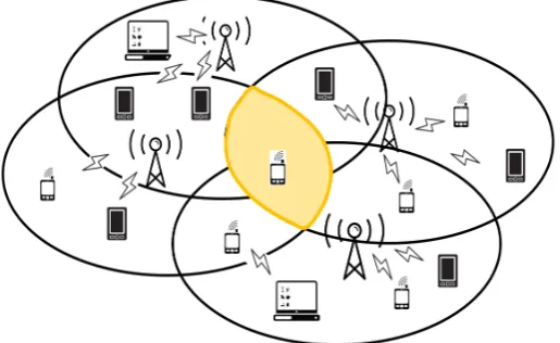
deployment of access points (APs) for increasing the user satisfaction. As a result, congestion and contention
16
problems among devices in overlapping basic service set (OBSS), as shown in Fig.1, become important, which
17
severely deteriorates the user experience. For efficiently handling this issue, the task group of IEEE 802.11ax
18
(TGax) is conducting IEEE 802.11ax standardization, in what is called the high-efficiency wireless local area
19
networks (HE-WLAN) fundamentally based on IEEE 802.11ac to address the congestion problems [2–5].
20
The 802.11ax HE-WLAN adopts a new scheme, called the multiple network allocation vectors (NAVs), in
21
order to mitigate the interference problem. Each IEEE 802.11ax-based Internet of Things (IoT) stations hold
22
multiple NAVs to avoid wireless congestion. If an STA is located in a certain area which is OBSS created by
23
three APs, the STA hold three different NAVs for the corresponding APs. Specifically, the NAV that is related to
24
the associated AP is calledintra-BSS NAVand the other NAVs are calledinter-BSS NAVs. The intra-BSS NAV
25
and inter-BSS NAVs are utilized for avoiding interference among STAs, which are located within associated AP
26
and other alien APs, respectively. If other STAs which are associated with the AP, then the intra-BSS NAV is set
27
and the STA should idle until the reception ofcontention free end framefrom the AP. On the other hand, if STAs
28
which are associated with other alien APs are communicating among themselves, the STA should be idle due
29
to the inter-BSS NAV. That is, multiple NAVs consist of intra-BSS NAV and inter-BSS NAVs. In addition, the
30
multiple NAVs behave strategically to avoid interference among STAs in OBSS networks and can be utilized
31
Preprints (www.preprints.org) | NOT PEER-REVIEWED | Posted: 15 August 2018 doi:10.20944/preprints201808.0263.v1
© 2018 by the author(s). Distributed under a Creative Commons CC BY license.
Figure 1.Scenario of hyper-dense APs: multiple inter-BSS NAVs may deteriorate medium utility chance of an STA in OBSS.
properly to transmit data for each STA. To sum up, if at least one of inter-BSS NAVs or intra-BSS NAV is set in a
32
specific subcarrier, the STA cannot transmit data because it assumes the channel is busy. Envisioning a future
33
WLAN which configures hyper-dense deployment of countless devices in a certain small area, STA may set
34
multiple inter-BSS NAVs and consequently it could be excessively delayed for even single transmission.
35
For avoiding excessive delay, we propose a novel algorithm to address the delay problem in an STA with
36
data in its data queue that needs to be transmitted and is blocked due to several inter-BSS NAVs or intra-BSS
37
NAV settings. This means that the multiple NAV can be helpful for avoiding interference problem but it can
38
be harmful for delay issues. Therefore, this paper targets a new objective, i.e., a joint optimization of delay
39
reduction and interference minimization. If the time interval of the idle state exceeds a threshold, the delayed
40
STA makes a decision which AP to be associated with the STA among its own AP and other alien APs and
41
swiftly finds a direction towards the candidate AP within a low time complexity. Finally, the STA configures a
42
beamformed-beam to transmit data to the designated AP to calculated direction. Our algorithm in IEEE 802.11ax
43
enables an STA to transmit data in densely deployed environment even though it has a set of inter-BSS NAVs or
44
an intra-BSS NAV. We demonstrate an analytical model of the proposed algorithm and simulate its performance
45
compared to IEEE 802.11 distributed coordination function (DCF) in terms of fairness and expected transmission
46
time loss.
47
The main contribution of this paper is the design of an algorithm which mitigates the delay issue of STAs in
48
the heavily dense deployment scenario of 802.11ax based IoT wireless networks. For this purpose, we firstly
49
propose low-complexity and swift beam direction selection algorithm that is based on opportunistic beamforming
50
MAC protocols. The rest of this paper is constituted as follows. Section2introduces related work and the
51
enhanced features of IEEE 802.11ax. Section3proposes an opportunistic beamforming algorithm and describes
52
the analytic model of the proposed algorithm. Section4performs intensive simulations and presents discussions
53
based on the simulation results. Finally, section5concludes this paper.
54
2. Related Work and IEEE 802.11ax Features 55
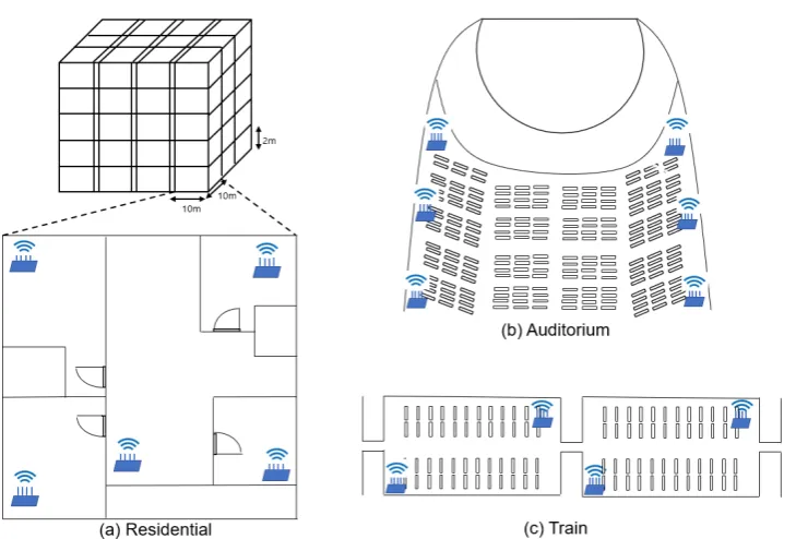
The dense deployment of IoT devices in the aforementioned scenario can be represented as in Fig.2.
56
IEEE 802.11ax is designed for high performance distributed networking in dense deployment scenarios, such
57
as carriages, residential apartments, and auditoriums. Based on the nature of IEEE 802.11ax, it is one of the
58
most suitable solutions for hyper-dense IoT wireless communications. By adopting the aforementioned multiple
59
NAV strategy, data transmission in dense deployment scenarios where tens of APs and hundreds of STAs co-exist
60
simultaneously in a small area can be delayed due to wireless medium resource competition. That is, we can
61
easily envision that each device should wait until all NAVs are reset when there exists multiple IoT devices which
3 of 15
Figure 2.Three densely deployed APs scenarios of wireless devices. Fig. (a) represents a plausible residential scenario which is composed of densely deployed multiple APs in an apartment. Fig. (b) is a scenario for multiple APs in an auditorium. Lastly, Fig. (c) is an example of densely installed APs scenario in a carriage.
want to aggressively utilize the air interface. In this section, previous research results and primary features of the
63
802.11ax standard are introduced.
64
The research results in [6] demonstrated a downlink multi-user MIMO (DL MU-MIMO) along with new
65
features of IEEE 802.11ax, i.e., uplink MU-MIMO (UL MU-MIMO) transmission in AP-initiated scenarios.
66
In [6], the differences between legacy IEEE 802.11 wireless local area networks (WLAN) and IEEE 802.11ax
67
were introduced. In addition, the analytical saturation throughput model of transmission scenarios for both
68
single-user (SU) and multi-user (MU) were proposed. Furthermore, the IEEE 802.11ax and IEEE 802.11ac were
69
compared in [7]. The insights of DL/UL orthogonal frequency division multiple access (OFDMA), dynamic clear
70
channel assessment (CCA), and UL MU-MIMO concepts were also introduced in [7]. Surveys on OFDMA-based
71
medium access protocols and OFDMA-based concurrent MU medium access control algorithms for IEEE
72
802.11ax were presented in [8,9].
73
The research results in [10,11] were focused on dynamically tuning of CCA which enhances spatial
74
reusability for addressing OBSS congestion problems. In terms of implementation, the link-system level
75
simulator for IEEE 802.11ax with network simulator 3 (NS3) was explored in [12]. In [12], plausible transmission
76
parameters, dense deployment scenarios, and the simulated throughput of each BSS with various numbers of
77
STAs were studied. The authors of [13] studied quality-of-service (QoS) support in legacy IEEE 802.11 wireless
78
networks and summarized the IEEE 802.11ax standardization processes. In addition, they presented an overview
79
of current and expected features of IEEE 802.11ax in terms of the medium access control. Moreover, emerging
80
long-term evolution licensed-assisted access which satisfied user needs with low latency and high bandwidth
81
were jointly considered with IEEE 802.11ax for collaboration between cellular networks and IEEE 802.11
82
WLAN-based wireless networks. Besides, the method in [14] suggested a next generation medium access control
83
mechanisms in unlicensed bands (5G-U) for vehicular radio access with licensed-assisted access (LAA) and
84
IEEE 802.11ax wireless networks. A new medium access control algorithm under the consideration of resource
85
uncertainty and physical sidelink shared channel (PSSCH) were proposed to deploy LTE vehicle-to-everything
86
(V2X), channel pre-occupation, and resource binding strategies. The algorithm in [15] proposed co-existence
87
mechanisms of IEEE 802.11ax with cellular, LTE with unlicensed (LTE-U), and LAA. The authors of [15]
88
considered single unlicensed frequency band transmissions that the locations of Wi-Fi STAs, Wi-Fi APs, and LTE
89
Preprints (www.preprints.org) | NOT PEER-REVIEWED | Posted: 15 August 2018 doi:10.20944/preprints201808.0263.v1
evolved node B (eNB) are modeled as three independent homogeneous Poisson point processes. They derived
90
analytical expressions for a set of metrics including signal-to-interference-plus-noise ratio coverage probability,
91
density of successful transmissions, and Shannon throughput probability for both of the UL and DL of IEEE
92
802.11ax wireless networks and cellular networks.
93
There exist several improvements in IEEE 802.11ax for various purposes to enhance data rate in order to
94
mitigate interference and improve the efficiency of frequency utilization. Among them, target wake time (TWT)
95
is one of the improvements in IEEE 802.11ax. The TWT has advantage in terms of collision probability reduction
96
in high-dense distributed IEEE 802.11-based WLAN network scenarios with pre-knowledge awake time of STAs
97
with associated AP. The mechanism of TWT is extremely simple yet effective by calculating and analyzing when
98
STA wakes up to transmit data over time. Furthermore, the TWT enables STAs to operate energy efficiently
99
with the doze mode. For example, authors in [16] proposed a scheduling scheme in IEEE 802.11ax with TWT
100
to efficiently handle multi-user transmissions and multi-AP cooperation. The authors in [17] explored several
101
new IEEE 802.11ax UL scheduling mechanisms and compared them among the maximum throughput of MU.
102
They conducted evaluations on MIMO and OFDMA transmissions in IEEE 802.11ax versus the carrier-sense
103
multiple access with collision avoidance (CSMA/CA) MAC of IEEE 802.11ac with the SU and MU modes for
104
various number of STAs scenarios in both reliable and unreliable channel environments. The authors of [18]
105
suggested advanced IEEE 802.11ax TCP-aware scheduling strategies to optimize the performance using MU UL
106
and MU DL transmissions. They were based on transmission opportunities (TXOP) and can control achieved
107
goodput versus delays. The authors showed that minimal goodput degradation strategy can avoid tremendous
108
delay. In [19], the authors proposed a semi-matching based load balancing scheme for hyper-dense IEEE 802.11
109
wireless networks. The scheme is operated in a centralized controller which makes decision whether the load
110
is unevenly distributed among APs and controls the overall network throughput to be maximized. By taking
111
advantage of IEEE 802.11ax new feature considerations, simultaneous transmit and receive (STR) which is
112
also called full-duplex, is likely to be applied in legacy IEEE 802.11-based wireless standards. One of the key
113
challenges is to integrate the STR mode with minimal modifications into legacy standards. In [20], the authors
114
proposed a simple yet practical approach to enable the STR mode in IEEE 802.11-based wireless networks
115
with co-existing full-duplex and half-duplex STAs. TGax for IEEE 802.11ax standardization plans to adopt
116
some new features such as dynamic CCA tuning, multiple network allocation vectors, and TWT. The TWT is
117
an energy efficient strategy in terms of the operation of STA considering that the associated AP of the STA has
118
full knowledge of awake schedule of the STA and thus the AP properly transmits data by calculating the awake
119
time of STA which is not in doze mode. In addition, a multi-NAVs strategy for efficient frequency utilization is
120
considered for mitigating wireless interference in hyper-dense situations. The STA set NAV for an AP where the
121
AP initiates transmission. If at least one of the inter-BSS NAVs or intra-BSS NAV of STA is set, the STA should
122
be idle for avoiding congestion until all NAVs are reset. In the following subsections, IEEE 802.11ax specific
123
wireless frame format and the error correction and modulation of IEEE 802.11ax are proposed.
124
2.1. PPDU frame structure
125
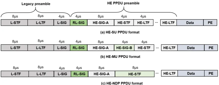
IEEE 802.11ax TGax standard changed the physical protocol data unit (PPDU) frame format compared
126
to IEEE 802.11ac for improving frequency, channel, and medium utilizations. As shown in Fig.3, the IEEE
127
802.11ax PPDU frame formats keep legacy preambles for backward compatibility and addRL-SIGfield behind
128
the legacy preambles for automatic detection of IEEE 802.11ax frames. In addition, IEEE 802.11ax IoT devices
129
detect channel state information (CSI) by referring to theL-LTFfield in Fig.3. If the result of modulo three
130
operations of the length field ofL-SIGis 1, the frame is for SU. If the result is 2, then the frame is for MU
131
transmission. A null data packet (NDP) frame for CSI exchange is in Fig.3(c) and is transmitted by AP. When an
132
STA receives NDP announce (NDPA) frame followed by NDP, the STA transmits CSI report frame to AP and the
133
AP transmits trigger frame as a response to CSI report to initiate UL transmission.
134
2.2. Error correction and modulation
135
The legacy IEEE 802.11 standard adopted block check character (BCC) for forward error correction (FEC),
136
and not the low density parity check (LDPC) due to its high computational cost. However, IEEE 802.11ax
5 of 15
Figure 3.IEEE 802.11ax PPDU frame format.
Table 1.A comparison between the IEEE 802.11ac and the IEEE 802.11ax
IEEE 802.11ac IEEE 802.11ax
Band [GHz] 5 2.4 and 5
Channel bandwidth [MHz] 20, 40, 80, 80+80, 160 20, 40, 80, 80+80, 160 Modulation BPSK, QPSK, 16QAM, 64QAM, 256QAM 1024QAM is newly added
FFT size 64, 128, 256, 512 256, 512, 1024, 2048
Subcarrier spacing [KHz] 312.5 78.12
Symbol duration [us] 3.2 12.8
CP [us] 0.4 and 0.8 0.8, 1.6, and 3.2
FEC BCC, LDPC (optional) LDPC
Spatial stream (SS) Up to 8 SS for each AP Up to 8 SS for each AP Up to 4 SS for each STA Up to 4 SS for each STA
MU-MIMO DL MU-MIMO UL/DL MU-MIMO
selects LDPC for error correction as mandatory because it performs better in terms of capacity compared to
138
IEEE 802.11ac. In addition, IEEE 802.11ax selectively utilizes dense constellation, such as 1024-QAM, so that
139
each symbol contains more information and achieves an improved throughput performance. Furthermore, IEEE
140
802.11ax exploits four-fold larger fast Fourier transform (FFT) size compared to the IEEE 802.11ac so that the
141
spectral efficiency can be improved for appropriate dense scenarios, as shown in Table1. Although its subcarrier
142
is narrower than before, the inter symbol interference (ISI) problem is relieved by setting longer guard interval
143
(GI). By utilizing these improvements in terms of medium access control, data transmission under severe delay
144
spread in outdoor environments can be successful.
145
3. Proposed Opportunistic Medium Access 146
In this section, we discuss an excessively long delay problem that may occur in IEEE 802.11ax and propose
147
a swift and low-complexity beam direction selection algorithm based on opportunistic beamforming medium
148
access control. First, the simplified mechanism of the DL and UL transmissions of IEEE 802.11ax is as illustrated
149
in Fig.4. In case of DL MU transmission, the data packets from an AP are transmitted simultaneously to multiple
150
STAs and each STA replies the correspondingblockACK to the associated AP. On the other hand, STAs, which
151
have packets to transmit simultaneously, send their packets as they receive thetrigger frame. In the following
152
subsections, the mechanism and analytical model of the proposed medium access control algorithms and related
153
assumptions are presented.
154
Preprints (www.preprints.org) | NOT PEER-REVIEWED | Posted: 15 August 2018 doi:10.20944/preprints201808.0263.v1
Figure 4.Simplified DL and UL transmissions of IEEE 802.11ax.
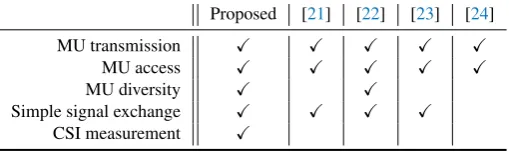
Table 2.Comparison with other OFDMA protocols
Proposed [21] [22] [23] [24]
MU transmission X X X X X
MU access X X X X X
MU diversity X X
Simple signal exchange X X X X
CSI measurement X
In terms of the various evaluation criteria used for our algorithms and previous research, and used for
155
comparison between the previous research [21–24] and our algorithm is proposed as Table 2. The MU
156
transmission and MU access represent feature of simultaneous channel access and concurrent data transmission
157
of STAs by taking advantage of the frequency orthogonality of OFDMA. Hence, channel access efficiency of
158
STAs can be enhanced by utilizing this feature. In addition, MU diversity stands for the characteristic that
159
each STAs can be allocated only high channel gain resource blocks (RBs) and can improve their throughput
160
performance. Simple signal exchange shows that simple control message exchange procedure in communication
161
system. In case of 802.11ax and our proposed protocol,triggerframe, which is one of the control message among
162
data transmission procedure, is related to this feature. Finally, channel state information (CSI) measurement item
163
refers to the measurement process of channel state between AP and STAs. The AP and STAs exchange the result
164
of this procedure and utilize the information of channel to appropriately tune their transmission parameters.
165
3.1. System model and assumptions
166
In order to understand our proposed algorithm, consider a simple IEEE 802.11ax network which consists
167
of multiple OBSSes with five APs and twenty STAs in a narrow area as presented in Fig.5(only two APs
168
and five STAs are represented for simplification). In particular, the user experience ofSTA2, which is our 169
main focus, is deteriorated during the red-lined duration in Fig.5due to multiple inter-BSS NAVs setting.
170
It is straightforward to envision that the red-lined duration will get longer while the more affected APs are
171
increased. Thus, this phenomenon can be much more severe and the STA hardly transmits data due to increased
172
delays in hyper-dense wireless networking scenarios. If affecting alien APs are relaying to transmit for each
173
transmission cycle, it is obvious that the STA gets the worst chance to transmit data. To address this issue, we
174
propose a low-complexity and swift beam direction selection algorithm based onopportunistic beamformingdata
175
transmission for letting delayed STA transmit data. Therefore, the proposed algorithm consists of two modules:
176
i) appropriate beamformee designation and direction configuration procedure and ii) data transmission through
177
the direction with beamforming.
178
In order to analyze our proposed algorithm in hyper-dense IEEE 802.11ax wireless networks, the following
179
assumptions are made.
7 of 15
Figure 5.Elongated delay scenario ofSTA2due to inter-BSS NAVsN AV1setting.
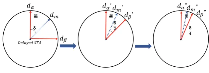
Figure 6.Detailed mechanism ofSearcheHR(hdα,dβi,BSR)in Algorithm 1.
• Each STA has exactly the same performances with OFDMA and MU-MIMO for mathematical performance
181
analysis.
182
• In addition, antennas which are installed in each IEEE 802.11ax IoT device are full-duplex vouching
183
simultaneous U/DL transmission.
184
• Detailed parameter setting of antennas for beamforming including azimuth, half power beam width
185
(HPBW), and antenna gains are not associated with the proposed algorithm.
186
• U/DL MU transmissions are considered in this paper.
187
• In our proposed algorithm, NAV is set to 0 if the corresponding AP is idle and vice versa.
188
3.2. Beam direction selection and beamforming algorithm
189
This section introduces a fast and lightweight beam direction selection based beamforming algorithms to
190
address the aforementioned issue in IEEE 802.11ax wireless networks. The main mechanisms of our algorithms
191
can be summarized as follows. i) If an STA attempts to transmit data, it considers its inter-BSS NAVs are set. If
192
all of them are reset then it immediately transmits data to its associated AP (line 14 of Algorithm 2). However,
193
if at least one of them is set, the STA should not act selfish to transmit data to avoid inter-BSS congestion
194
deterioration. In addition, the delayed STA due to inter-BSS NAV setting investigates a new AP to associate after
195
a specific durationθed, i.e., the STA haswait thresholdvariableωto avoid excessive delays and only finds the 196
appropriate direction of beamformee after theωexceeds waiting thresholdθed(line 3 of Algorithm 2). ii) After 197
the STA makes decision to find the beamformee, it chooses the associated AP or alien APs by sorting them based
198
on a descending order of their signal strengths (line 2 of Algorithm 1) and finds the most appropriate direction
199
(line 3 to 13 of Algorithm 1). iii) STA beamfoms toward its beamformee in the direction ofdir, which is the
200
result of Algorithm 1 (line 7 to 11 of Algorithm 2). Notice that the beam alignment procedure is recursively
201
Preprints (www.preprints.org) | NOT PEER-REVIEWED | Posted: 15 August 2018 doi:10.20944/preprints201808.0263.v1
Algorithm 1Joint searching for direction and CSI
Input: LRadir,HRadir,APCSa ,CSIAPe CS,HR
e
dir,dα,dβ
Output: Appropriatedirectionfor beamforming
1: Initialize Beam search rate (BSR)
2: Listen channel
3: ifAPais dominantthen
4: LRadir=SearchaLR(APCSa ,BSR)
5: HRadir=SearchaHR(LRadir,BSR)
6: returnHRadir
7: else
8: Sortcandidate APesbased onsignal strength
9: Selectdominant alien APe
10: Sethdα,dβi
11: HRedir=SearcheHR(hdα,dβi,BSR)
12: SetCSIAPCSe
13: returnhHRedir,CSIAPe CS i 14: end if
called as in Fig.6for finding the suitable beam direction angle (azimuth and elevation angle of beamforming)
202
between the delayed STA and target AP which is within the range of the HPBW of STA. The STA actively
203
searches with a beam search rate (BSR) between the originally associated AP or other the alien APs based on the
204
received signal strength indicators (RSSI) of each AP given that the wireless data traffic loads on each AP are
205
closely similar so that the RSSI is a proper criterion for selecting the AP.
206
Algorithm 2Proposed beamforming algorithm
Input: HRa
dirorhHRedir,CSIAPe
CS i,ω,θed,dir 1: Check∀inter−BSSN AVA[i]
2: if∃inter-N AVA[i]issetthen
3: ifω<θedthen
4: Increaseω
5: else
6: dir= Result ofAlgorithm1
7: ifdirisHRadirthen
8: Beam f ormtoHRadir
9: else
10: Beam f ormwithhHRedir,CSIAPe CSi 11: end if
12: end if
13: else
14: Immediately transmitDATAthroughAPa
15: end if
Based on our assumptions, if the STA chooses to transmit data via its associated APa, it utilizes the
207
corresponding information which already has and exploits it for searching direction set of AP in low resolution
208
(LRadir) within (APCSa ) direction set under BSR (line 4 of Algorithm 1). After that, the STA searches a beamformee
209
with a higher resolution (HRdira ) by exploiting the result of low resolution direction (line 5 of Algorithm 1). The
210
main difference between low resolution and high resolution is the searching direction size in a circular sector
211
(CS) scale, which is the range of direction searching procedure where low resolution is wider than the high
9 of 15
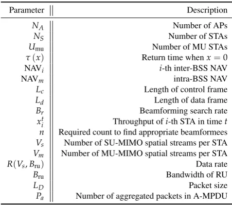
Table 3.Parameters used in analysis
Parameter Description
NA Number of APs
NS Number of STAs
Umu Number of MU STAs
τ(x) Return time whenx=0
NAVi i-th inter-BSS NAV
NAVm intra-BSS NAV
Lc Length of control frame
Ld Length of data frame
Br Beamforming search rate
xt
i Throughput ofi-th STA in timet n Required count to find appropriate beamformees Vs Number of SU-MIMO spatial streams per STA Vm Number of MU-MIMO spatial streams per STA R(Vs,Bru) Data rate
Bru Bandwidth of RU
LD Packet size
Pa Number of aggregated packets in A-MPDU
resolution’s one. On the other hand, if the STA chooses to transmit among one of the alienAPes, the STA sorts
213
them considering the signal strength with a descending order and selects one of them (line 8 to 9 of Algorithm
214
1). Later, the STA sets CSI betweendαanddβ, which is the initial range of searching direction area (line 10 215
of Algorithm 1), and finds the direction of targeted alien AP (HRedir) by callingSearcheHRfunction recursively
216
while dynamically tuning thedαanddβper every function call (line 11 of Algorithm 1). The detailed operation 217
ofSearcheHR(hdα,dβi,BSR)is represented in Fig.6. After these processes, the STA finally sets up CSI between 218
the selectedAPeand gets the joint beamforming information (line 12 to 13 of Algorithm 1). Finally, it can be
219
observed that the STA addresses delay issue and the STA can transmit data to eitherAPaorAPein the direction
220
of the calculated result in order to improve the performance in terms of the interference reduction.
221
To sum up, the STA with our proposed beamforming algorithm in hyper-dense environments does not act
222
selfishly but little tenacious to cooperate with other STAs in OBSS to avoid wireless congestion. In addition,
223
as illustrated in Fig.6, if the STA makes a decision to associate withAPes, then finding a dominantAPeand
224
searching appropriate beam direction are required with the complexity ofO(nlog(n)), according to the fact
225
that finding dominant APe among APesrequiresO(n)and searching appropriate beam direction requires
226
O(log(n)).
227
3.3. Analytical model
228
In this section, the total elapsed time for D/UL MU transmissions are formulated. This measurement is used
229
for calculating the lost time of the denied transmission of STA and can be utilized for computing the expected
230
lost throughput. The analysis regarding the expected lost throughput can be conducted with the expected lost
231
time as red-lined in Fig.5. Furthermore, fairness on wireless medium access is also used to compare DCF with
232
our proposed algorithm using Jain’s index [25]. The used parameters and descriptions for the mathematical
233
analysis are summarized in Table3.
234
3.3.1. Total elapsed time of D/UL MU transmission
235
STAs which communicate with AP for D/UL follow specific transmission procedure as defined in the IEEE
236
802.11ax TGax standardization.
237
In case of DL MU transmission, AP initiates IEEE 802.11ax-based transmission procedure by sending
238
request-to-send (RTS) frame to its associated STAs. After short inter frame space (SIFS), STAs responds with a
239
clear-to-send (CTS) to the AP announcing that they are ready for receiving DL MU transmission data. Then,
240
Preprints (www.preprints.org) | NOT PEER-REVIEWED | Posted: 15 August 2018 doi:10.20944/preprints201808.0263.v1
the AP concurrently transmits DL MU data to STAs. After receiving all data from the AP, STAs responds
241
with block acknowledgement (BACK) to the AP in order to inform successful reception. Finally, the AP sends
242
contention-free-end (CFE) to reset its NAV of STAs.
243
In case of UL MU transmission, STAs which want to upload data to AP send MU RTS frame to the AP.
244
The AP responds with CTS and sends NDP/NDPA frames before transmittingtriggerframe which initiates
245
STAs’ UL MU transmission. After STAs trigger frame reception, the STAs concurrently transmit their data.
246
After the termination of STAs’ data transmission procedure, the AP sends MU ACK back to STAs for informing
247
successful UL data transmission. Finally, it transmits CFE to STAs, same as in the DL procedure and STAs reset
248
corresponding NAV.
249
Based on this description, the total elapsed time for a single downlink and uplink MU transmission can be
250
formulated as (1) and (2), respectively.
251
Tmud (Umu,Vs,Bru) = Tmu-RTS(Umu) +TSIFS+TCTS+TSIFS+TmuDATA,d (Umu,Vs,Bru) +TSIFS+
TBA+AIFS+Te (1)
Tmuu (Umu,Vm,Vs,Bru) = Tmu-RTS(Umu) +TSIFS+TCTS+TSIFS+Ttrigger(Umu) +
TSIFS+TmuDATA,u (Vs,Bru) +TSIFS+Tmu-ACK(Vm) +Te (2)
The above two equations, i.e., (1) and (2), include the elapsed time of backoff, data transmission time, and
252
control frames exchange times in D/UL transmission.Td
mu(Umu,Vs,Bru)andTmuu (Umu,Vm,Vs,Bru)refer to the
253
total duration of DL and UL MU transmission respectively. They include commonlyTmu-RTS(Umu) +TSIFS+
254
TCTS+TSIFSfor initial control message exchange procedure. TmuDATA,d (Umu,Vs,Bru)in DL MU transmission
255
represent required time for data transmission forUmuwithR(Vs,Bru)per each STA. After the transmission
256
of data through DL after SIFS, STAs transmit BACK, which consumesTBA and idle for AIFS+Te which 257
is the duration of arbitrary inter symbol space (AIFS) and CFE.Ttrigger(Umu)in UL MU transmission and
258
TDATA
mu,u (Vs,Bru)stand for the duration of trigger frame toUmuUL MU STAs and the required time for MU UL
259
data transmission, respectively. Finally, after SIFS,Tmu-ACK(Vm) +Teis required for terminating entire UL 260
MU transmission procedures. These are utilized to calculate the cost values of expected lost timelt(refer to 261
Section3.3.2) and the expected lost throughputELTh (refer to Section3.3.3) in the following subsections. 262
3.3.2. Expected lost timelt 263
Theτfunction that is defined as 264
lt=τ NA
∑
i=0NAVi !
−τ(NAVm) (3)
is used for calculating the total time difference depending on NAV values when intra-BSS NAV and all other
265
inter-BSS NAVs are reset to zero. The (1) and (2) are used to calculate the time of each NAV duration. Thus,
266
the (3) represents the delayed period of an STA affected by the inter-BSS NAVs set which are generated by
267
neighboring APs in dense deployment environments.
268
3.3.3. Expected throughput loss,ETh 269
11 of 15
ES represents the average neighboringNS. The expected loss of control and data frames can be analytically
formulated as in the following; (4) and (5).
ELc=lt·
lc
R(1,20MHz)
| {z }
Tc∗
·lt·
1−Br
lt
n−n1
·
Br
lt
1n
| {z }
Pc∗
(4)
whereELcstands for the expected throughput loss of control frame. In (4),T ∗
c denotes the throughput loss during 270
ltwith
l
lc
R(1,20MHz) m
size of control frame per unit time andPc∗stands for the successful probability to find the 271
appropriate beamformee with beam search rateBrin time periodltinncounts. 272
Similarly, the expected throughput loss of data frame, i.e.,ELd, can be formulated as follows:
ELd =lt·
ld
R(Vs,Bru)
| {z }
T∗
d
·ld·
1−Br
lt
n−n1
·
Br
lt
1n
| {z }
P∗
d
(5)
whereTd∗andPd∗denote the throughput loss durationltwith data rateR(Vs,Bru)and successful probability for 273
finding the appropriate beamformee with beam search rateBrfor the durationltinncounts, respectively. 274
3.3.4. Jain’s indexJ for fairness
275
Finally, the total expected loss of throughput can be denoted by:
ELTh =ELc+ELd. (6)
In addition, the medium access fairness can be evaluated by the following Jain’s index, i.e.,
J xt1,x2t,· · ·,xit ,
∑NS
i=1xti
2
NS·∑iN=S1 xit
2 (7)
which each ofxti represents throughput ofi−thSTA in time stept.
276
4. Performance Evaluation 277
In this section, we discuss the simulation setting and results regarding delay scenario which is considered in
278
the previous section. We simulate the denied transmission period based on the analytic model which is presented
279
in the previous section for both U/DL MU transmission. Moreover, we evaluate our proposed medium access
280
control protocol in terms of fairness using Jain’s index. We compare the fairness values of the ordinary DCF and
281
the proposed algorithm under different options and various numbers of STAs.
282
4.1. Simulation setting and overview
283
Our simulation is designed and implemented based on the assumptions and formulations in Section3and
284
Table3, in order to precisely operate with obeying these settings. The parameters and corresponding values used
285
in our simulation are summarized in Table4. There are 8 APs and STAs from 4, 8, 16, 32, and 64, which always
286
have data in the data queue to transmit to the associated AP (i.e., saturated conditions). Among the STAs, we
287
specifically designed a delay scenario where the inter-BSS NAVs of specific target STA is successively set due to
288
neighboring APs which successively initiate transmission with their associated STAs. Thus, the STA is delayed
289
because of successive set of inter-BSS NAVs, and has to wait until all of them are reset. The delay duration of the
290
STA can be minimized to nearly wait time thresholdθedin Algorithm 2 by taking advantage of our proposed 291
algorithms above.
292
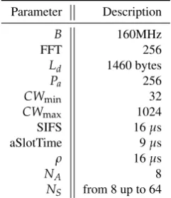
Preprints (www.preprints.org) | NOT PEER-REVIEWED | Posted: 15 August 2018 doi:10.20944/preprints201808.0263.v1
Table 4.Simulation parameters
Parameter Description
B 160MHz
FFT 256
Ld 1460 bytes Pa 256 CWmin 32 CWmax 1024
SIFS 16µs
aSlotTime 9µs
ρ 16µs
NA 8
NS from 8 up to 64
The total bandwidth of a carrier is 160MHz and FFT size is adopted as 256. In addition, the aggregated
293
medium access control protocol data unit (A-MPDU) consists ofPapackets with symbol duration in the length 294
ofρ(16µs) is used for transmission simulations. The size oflcincluding ACK, SIFS, and other control frames is 295
set to 123bytes andldis 1460bytes. In addition,Paframes in the size ofldare aggregated as an A-MPDU for 296
simulations. Moreover, the AP with 8 antennas serves STAs that each of them is equipped with 2 antennas for
297
enabling transmission through multiple spatial streams.
298
First, we simulate the time loss in U/DL transmission under hyper-dense deployment scenarios varying
299
modulation and coding scheme (MCS) levels and the number of STAs which delay an STA such asSTA2in 300
Fig.5. Furthermore, dense constellations which supports up to 32 STAs are considered to evaluate the stability of
301
time loss for the delayed STA. In addition, the fairness of the medium access for each STA is compared with
302
DCF by calculating Jain’s index.
303
4.2. Simulation results and discussions
304
Theltvalues of DL and UL MU transmission are simulated in dense deployment environments under the 305
various MCS and STAs numbers, as presented in Fig.7and Fig.8. Based on (3), the time loss of STA is measured
306
using the parameters in Table4. The time loss of STA is sharply increased as the number of neighboring STAs is
307
added. As the number of interfering STAs reaches 64, the STA which uses MCS9 and MCS10 cannot transmit
308
any data in effect. The reason for this phenomenon is caused by multi-NAVs policy of IEEE 802.11ax where the
309
inter-BSS NAVs are increased to manage the possible congestion for STA. Furthermore, the inter-BSS NAVs are
310
proportional to the number of neighboring or interfering APs and associated STAs.
311
13 of 15
Figure 8.Expected time lossltfor UL transmission.
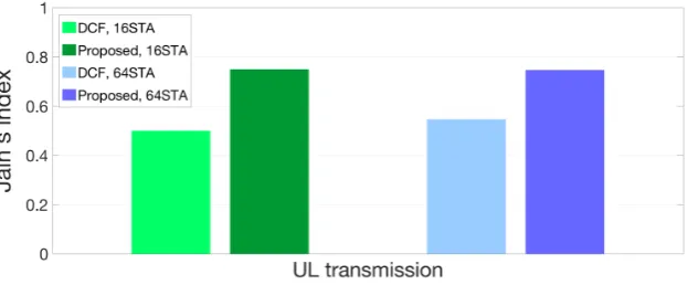
Finally, Fig.9and Fig.10represent a comparison of fairness index values for medium access between DCF
312
and our proposed algorithm. The fairness of our proposed algorithm is improved to 44% and 31% compared to
313
DCF when the numbers of STAs are 16 and 64 respectively in DL transmission. In case of UL transmission,
314
the fairness is improved up to 50% and 36% when the numbers of interfering STAs are 16 and 64 respectively.
315
In conclusions, our proposed algorithm enhances the fairness of the channel access efficiency in hyper-densely
316
deployed environments in order to minimize the delay time.
317
Figure 9.Fairness comparison between DCF and proposed protocol in DL scenario
Figure 10.Fairness comparison between DCF and proposed protocol in UL scenario
5. Conclusion Remarks 318
In this paper, we demonstrated the possible delay problem of IEEE 802.11ax in a hyper-dense deployment of
319
IoT wireless devices due to multiple inter-BSS NAVs settings and analyzed the expected lost time and throughput
320
of victim STAs. To address this issue, we first propose a swift and low-complexity beam direction selection
321
algorithm based on an opportunistic beamforming for IEEE 802.11ax-based IoT systems in terms of the joint
322
optimization of delay reduction and interference mitigation. In addition, we evaluated the performance of our
323
Preprints (www.preprints.org) | NOT PEER-REVIEWED | Posted: 15 August 2018 doi:10.20944/preprints201808.0263.v1
proposed algorithm in terms of the throughput and fairness, and clearly show that our proposed algorithm can
324
achieve a desired performance.
325
Author Contributions:D. Kwon, J. Kim, and A. Mohaisen were the main researchers who initiated and organized research 326
reported in the paper, and all authors including S.-W. Kim were responsible for analyzing the simulation results and writing 327
the paper. 328
Funding:This research was funded by Chung-Ang University Research Grant (2018). 329
Acknowledgments:J. Kim and A. Mohaisen are the corresponding authors of this paper. 330
Conflicts of Interest:The authors declare no conflict of interest. 331
Acknowledgment 332
References 333
1. Cisco, "Cisco Visual Networking Index: Forecast and Methodology 2016–2021," Sept. 15, 2017. Available 334
online: https://www.cisco.com/c/en/us/solutions/collateral/service-provider/visual-networking-index-vni/complete-335
white-paper-c11-481360.html(accessed on 25th, July, 2018) 336
2. Afaqui, M. S.; Villegas, E. G.; Aguilera, E. L. IEEE 802.11ax: Challenges and Requirements for Future High Efficiency 337
WiFi.IEEE Wireless Communications,2017,24130–137. 338
3. Khorov, E.; Kiryanov, A.; Lyakhov, A. IEEE 802.11ax: How to Build High Efficiency WLANs. In Proceedings of the 339
IEEE Engineering and Telecommunication (EnT), Moscow, Russia, 18–19 November 2015; pp. 14–19. 340
4. Omar, H. A.; Abboud, K.; Cheng, N.; Malekshan, K. R.; Gamage, A. T.; Zhuang, W. A Survey on High Efficiency 341
Wireless Local Area Networks: Next Generation WiFi. IEEE Communication Surveys and Tutorials, 2016, 18, 342
2315–2344. 343
5. B, Bellalta. IEEE 802.11ax: High-Efficiency WLANs.IEEE Wireless Communications,2016,23, 38–46. 344
6. Bellalta, B.; Kosek-Szott, K. AP-initiated Multi-User Transmissions in IEEE 802.11ax WLANs. arXiv 2017, 345
arXiv:preprint/1702.05397. 346
7. Gong, M. X.; Hart, B.; Mao, S. Advanced Wireless LAN Technologies: IEEE 802.11AC and Beyond.ACM GetMobile: 347
Mobile Computing and Communications,2014,18, 48–52. 348
8. Li, B.; Qu, Q.; Yan, Z.; Yang, M. Survey on OFDMA based MAC Protocols for the Next Generation WLAN. In 349
Proceedings of the IEEE Wireless Communications and Networking Conference Workshop (WCNC WKSHPS), 350
Istanbul, Turkey, 9–12 May 2015; pp. 131–135 351
9. Qu, Q.; Li, B.; Yang, M.; Yan, Z. An OFDMA based Concurrent Multiuser MAC for Upcoming IEEE 802.11ax. 352
In Proceedings of the IEEE Wireless Communications and Networking Conference Workshop (WCNC WKSHPS), 353
Istanbul, Turkey, 9–12 May 2015; pp. 136–141 354
10. Afaqui, M. S.; Villegas, E. G.; Lopez-Aguilera, E. Dynamic Sensitivity Control Algorithm Leveraging Adaptive 355
RTS/CTS for IEEE 802.11ax. In Proceedings of the IEEE Wireless Communications and Networking Conference 356
(WCNC), Doha, Qatar, 3–6 April 2016; pp. 1–6 357
11. Afaqui, M. S.; Garcia-Villegas, E.; Lopez-Aguilera, E.; Smith, G.; Camps, D. Evaluation of Dynamic Sensitivity Control 358
Algorithm for IEEE 802.11ax. In Proceedings of the IEEE Wireless Communications and Networking Conference 359
(WCNC), Istanbul, Turkey, 9–12 May 2015; pp. 1060–1065 360
12. Lin, W.; Li, B.; Yang, M.; Qu, Q.; Yan, Z.; Zuo, X.; Yang, B. Integrated Link-System Level Simulation Platform 361
for the Next Generation WLAN-IEEE 802.11ax. In Proceedings of the IEEE Global Communications Conference 362
(GLOBECOM), Washington D.C., USA, 4–8 December 2016; pp. 1–7 363
13. Deng, D. J.; Lien, S. Y.; Lee, J.; Chen, K. C. On Quality-of-Service Provisioning in IEEE 802.11 ax WLANs.IEEE 364
Access,2016,4, pp. 6086–6104. 365
14. Lien, S. Y.; Deng, D. J.; Tsai, H. L.; Lin, Y. P.; Chen, K. C. Vehicular Radio Access to Unlicensed Spectrum.IEEE 366
Wireless Communications,2017,24, pp. 46–54. 367
15. Ajami, A. K.; Artail, H. On The Modeling and Analysis of Uplink and Downlink IEEE 802.11 ax Wi-Fi with LTE in 368
Unlicensed Spectrum.IEEE Transactions on Wireless Communications,2017,16, pp. 5779–5795. 369
16. Nurchis, M.; Bellalta, B. Target Wake Time: Scheduled access in IEEE 802.11 ax WLANs. arXiv 2018, 370
15 of 15
17. Sharon, O.; Alpert, Y. Scheduling Strategies and Throughput Optimization for the Uplink for IEEE 802.11 ax and IEEE 372
802.11 ac Based Networks.arXiv2018, arXiv:preprint/1803.10657. 373
18. Sharon, O.; Alpert, Y. Advanced IEEE 802.11 ax TCP aware scheduling under unreliable channels. arXiv2018, 374
arXiv:preprint/1803.10649. 375
19. Lei, T.; Wen, X.; Lu, Z.; Li, Y. A Semi-Matching Based Load Balancing Scheme for Dense IEEE 802.11 WLANs. 376
IEEE Access,2017,5, pp. 15332–15339. 377
20. Aijaz, A.; Kulkarni, P. Simultaneous Transmit and Receive Operation in Next Generation IEEE 802.11 WLANs: A 378
MAC Protocol Design Approach.arXiv2017, arXiv:preprint/1706.07544. 379
21. Kwon, H.; Seo, H.; Kim, S.; Lee, B. G. Generalized CSMA/CA for OFDMA Systems: Protocol Design, Throughput 380
Analysis, and Implementation Issues.IEEE Transactions on Wireless Communications,2009,8, pp. 4176–4187. 381
22. Kwon, H.; Kim, S.; Lee, B. G. Opportunistic Multi-Channel CSMA Protocol for OFDMA Systems.IEEE Transactions 382
on Wireless Communications,2010,9, pp. 1552–1557. 383
23. Lou, H.; Wang, X.; Fang, J.; Ghosh, M.; Zhang, G.; Olesen, R. Multi-User Parallel Channel Access for High Efficiency 384
Carrier Grade Wireless LANs. In Proceedings of the IEEE International Conference on Communications (ICC), Sydney, 385
NSW, Australia, 10–14 June 2014; pp. 3868–3870 386
24. Jung, J.; Lim, J. Group Contention-Based OFDMA MAC Protocol for Multiple Access Interference-Free in WLAN 387
Systems.IEEE Transactions on Wireless Communications,2012,11, pp. 648–658. 388
25. Jain, R. K.; Chiu, D. M. W.; Hawe, W. R. “A quantitative measure of fairness and discrimination for resource 389
allocation," in shared computer system, vol. 38, Hudson, MA, USA: Eastern Research Laboratory, Digital Equipment 390
Corporation, 1984. Available online: https://www.researchgate.net/profile/Raj_Jain3/publication/220486705_ 391
A_Quantitative_Measure_Of_Fairness_And_Discrimination_For_Resource_Allocation_In_Shared_Computer_ 392
Systems/links/09e4150c0274cec7b2000000.pdf(accessed on 25th, July, 2018) 393
Preprints (www.preprints.org) | NOT PEER-REVIEWED | Posted: 15 August 2018 doi:10.20944/preprints201808.0263.v1