Article
1
Techno-economic analysis of high-pressure metal
2
hydride compressor systems
3
Claudio Corgnale*, Martin Sulic
4
Greenway Energy, 301 Gateway Drive, Aiken, SC (USA), 29803
5
* Correspondence: [email protected]; Tel.: +1-803-617-9689
6
7
Abstract: Traditional high pressure mechanical compressors account for over half of the car station’s
8
cost, have insufficient reliability and are not feasible for a large-scale fuel cell market. An alternative
9
technology, employing a two-stage, hybrid system based on electrochemical and metal hydride
10
compression technologies, represents an excellent alternative to conventional compressors. The
11
high-pressure stage, operating at 100-875 bar, is based on a metal hydride thermal system. A
techno-12
economic analysis of the metal hydride system is presented and discussed. A model of the metal
13
hydride system was developed, integrating a lumped parameter mass and energy balance model
14
with an economic model. A novel metal hydride heat exchanger configuration is also presented,
15
based on mini-channel heat transfer systems, allowing for effective high-pressure compression.
16
Several metal hydrides were analyzed and screened, demonstrating that one selected material,
17
namely (Ti0.97Zr0.03)1.1Cr1.6Mn0.4, is likely the best candidate material to be employed for high-pressure
18
compressors under the specific conditions. System efficiency and costs were assessed based on the
19
properties of currently available materials at industrial levels. Results show that the system can
20
reach pressures on the order of 875 bar with thermal power provided at approximately 150 °C. The
21
system cost is comparable with the current mechanical compressors and can be reduced in several
22
ways as discussed in the paper.
23
Keywords: High pressure hydrogen; Metal hydride-based high pressure compression;
Techno-24
economic analysis; Ti-based AB2 metal hydrides; Mini-channel heat exchanger
25
26
1. Introduction
27
One of the main hurdles to be overcome for a large-scale hydrogen economy is relative to the H2
28
delivery. The United States Department of Energy (DOE) has essentially identified three approaches
29
to transport and delivery hydrogen at large scale [1]. Each of the scenarios requires the presence of
30
high pressure hydrogen systems. Currently DOE set its fueling pressure targets at approximately 875
31
bar, with inlet hydrogen at about 100 bar, and with flow rates up to 100 kg/h [1]. Among the other
32
targets for hydrogen compression systems, DOE identified the uninstalled cost target for the FY 2020
33
at 275,000 $, the energy requirement at 1.6 kWh/kg, availability equal to 85% and annual maintenance
34
cost equal to 4% of the uninstalled cost1 [1]. Currently, mechanical compressors cannot achieve the
35
DOE targets and have several additional drawbacks working at the specified operating conditions.
36
Valid alternative processes are represented by hybrid systems comprised of electrochemical
37
compression (EHC) systems, operating at lower pressures (10-100 bar), integrated with thermal
38
compression systems, operating at pressures on the order of 100-875 bar. One of the main advantages
39
of a hybrid system over other alternative solutions is in the possibility of recovering the available
40
waste heat from the EHC to pressurize and discharge the hydrogen from the thermal compression
41
system, based on metal hydrides. The work presented here focuses on the high-pressure metal
42
hydride-based compression system. Metal hydride materials absorb hydrogen through an
43
1 The targets are for: inlet pressure of 100 bar, hydrogen flow rate of 100 kg/h [1]
exothermic chemical reaction and release the absorbed hydrogen reversibly, through an endothermic
44
chemical reaction. The chemical reaction equilibrium pressures are direct functions of the operating
45
temperatures. Therefore, hydrogen can be absorbed in the materials at low temperatures and
46
corresponding low pressures. By providing high temperature thermal power, the hydrogen can be
47
released at high pressure without the use of external electric power.
48
A comprehensive review of the available MH materials, heat transfer and pressure vessel
49
concepts, operating at maximum pressures on the order of 600-700 bar, can be found in Reference [2].
50
Currently, available MHs for high pressure hydrogen compression are Ti-based materials (laves
51
phase, or AB2 phase materials). Depending on the material formulation, MH compressors can achieve
52
pressures on the order of 800-900 bar at temperatures on the order of 120-150 °C without any electric
53
input [3-4]. Recent research and development work focused on the design of high pressure MH-based
54
compression systems, examining the technical performance of the proposed material heat exchanger
55
coupled solutions. Gkanas et al. [5] propose the use of a two-stage metal hydride compression system
56
to achieve maximum pressure ratios of 22, with a maximum delivery pressure of 320 bar at 130 °C.
57
The first stage material is an AB5 alloy, namely LaNi5, while the second stage material is an AB2 type
58
material based on Zr-V-Mn-Nb. Karagiorgis et al [6] investigate the use of MH materials to compress
59
hydrogen, using waste heat available at temperatures in the range 10 – 80 °C. Maximum compression
60
ratios of about 32 were achieved, compressing hydrogen between 7 bar and 220 bar. However, the
61
system is comprised of 6 stage metal hydride compressors, using AB5 and AB2 materials. Galvis et al.
62
[7] also analyze the use of a three stage MH compressor, comprised of AB2 type materials
(Ti-Zr-Cr-63
Mn-V), to achieve an overall compression ratio of about 82. The system was designed to reach a
64
pressure of 115 bar, with inlet pressure of 1.4 bar, with maximum desorption temperature of 100 °C.
65
None of the proposed systems was designed for pressures on the order of 875 bar, as required by the
66
DOE targets and, consequently, the techno-economic feasibility of systems achieving very high
67
pressures was never examined.
68
The present work describes a techno-economic model applied to candidate high pressure metal
69
hydride materials for high pressure hydrogen compression. The model includes lumped parameter
70
steady state mass and energy balance equations, integrated with an economic model. The technical
71
performance of the overall material-heat exchanger system was assessed and discussed, proposing a
72
novel heat transfer system model, based on mini-channel cylindrical tubes heat exchangers. The
73
potential of available materials to meet the targets is also discussed, with proposed solutions to
74
enhance the economic performance.
75
2. The hybrid hydrogen compressor concept
76
A two-stage hybrid compressor system is proposed, as an alternative to conventional mechanical
77
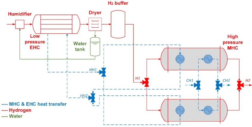
compressors, for efficient and low cost high-pressure hydrogen compression systems. A simplified
78
schematic of the proposed concept is shown in Figure 1. The first stage is based on an electrochemical
79
system, referred to as ‘Low pressure EHC’. The second stage is a pure thermal compression system,
80
based on metal hydride materials, referred to as ‘High pressure MHC’.
81
The EHC stage operates at manometric compression ratios on the order of 10, compressing the
82
hydrogen from an inlet pressure of 10 bar up to approximately 100 bar. Molecular hydrogen is
83
oxidized at the anode of an electrochemical system producing protons and electrons. The protons are
84
driven through a proton exchange membrane and combined with electrons at the cathode to deliver
85
high-pressure hydrogen. The outlet pressure is maintained at relatively low values (100 bar) in order
86
to minimize hydrogen back diffusion across the membrane. The inlet hydrogen flow needs to be
87
humidified to operate the electrochemical compression effectively using traditional Nafion®
88
membranes. A dryer unit at the exit of the first stage compressor separates the compressed gas from
89
the water, which is collected in a liquid tank unit. The water is recirculated in the humidification unit
90
to assure the right level of humidity in the electrochemical system. The hydrogen at the exit of the
91
first stage is stored in a buffer tank to assure a continuous flow in the thermal stage of the system.
92
The second stage (MHC stage) of the hybrid system operates at higher pressures with the objective
93
of achieving pressures on the order of 875 bar as required by the DOE targets. This stage is comprised
of a thermal compression system, based on MH materials. Such materials absorb hydrogen through
95
an exothermic chemical reaction and release the absorbed hydrogen reversibly, through an
96
endothermic chemical reaction. The equilibrium pressures for the chemical reactions are a direct
97
function of their operating temperatures. Therefore, hydrogen can be absorbed at low temperatures
98
and pressures and, by providing higher temperature thermal power during the desorption process,
99
the hydrogen pressure can be increased without the use of any external electric power.
100
101
102
103
Figure 1. Hybrid EHC/MHC system concept.
104
105
Each metal hydride unit intrinsically operates in a batch (or discontinuous) mode, either in
106
hydrogen charging mode or in hydrogen release mode. Therefore, to assure steady hydrogen flow,
107
at least two parallel metal hydride units need to be coupled in series with the electrochemical unit
108
(Figure 1). One of the main advantages of the proposed solution over competing approaches (e.g.
109
pure thermal compressor or pure electrochemical system) is the possibility of recovering the EHC
110
waste heat to feed the thermal MH system during hydrogen desorption, as shown in Figure 1. This
111
substantially increases the overall system efficiency [3]. The point HH1 identifies the inlet condition
112
of the hot utility (i.e. from the EHC) heat transfer fluid, while the HH2 point represents the
113
corresponding outlet condition, after hydrogen desorption in the MHC unit. The waste heat from the
114
EHC unit is available at temperatures on the order of 150-160 °C. The hydrogen is charged in the
115
MHC system using external cold utility (i.e. water at temperature on the order of 10-15 °C) heat
116
transfer. The points CH1 and CH2 in Figure 1 represent the inlet and outlet points of the cold utility
117
fluid, respectively. Depending on the EHC membrane selection and on the MHC material choice, the
118
system has the potential to achieve a complete EHC waste heat recovery without the need for external
119
thermal power input [3].
120
More information on the overall system and on the EHC stage characteristics, especially relative
121
to the energy integration with the MHC stage, can be found elsewhere [3]. The attention of the work
122
discussed in the current document was paid on the high pressure thermal compression unit,
123
examining the techno-economic performance of the MH systems.
124
3. The techno-economic analysis model
125
A simplified lumped parameter techno-economic model was developed to assess the
126
performance of the high-pressure MH compression system.
127
3.1. Metal hydride compressor system technical performance model
The metal hydride system model includes steady state lumped parameters mass and energy
129
balance equations. With reference to Figure 1, the mass balance equation of the MHC stage is
130
expressed as:
131
̇ = ̇ (1)
Equation 1 is valid assuming continuity of operation and represents the steady state balance of
132
mass for the MHC system. The hydrogen flow is split between the two parallel metal hydride units.
133
The lumped parameter steady state energy balance equation is expressed as:
134
̇ ℎ − ̇ ℎ
= ( + )( − )
∆ + ̇ ∆
−( + )( − )
∆ + ̇ ∆
(2)
with h being the hydrogen specific enthalpy (kJ/kg), MMH and Mw being the mass of each metal
135
hydride material and of the tubing walls (kg), CPMH and CPW being the specific heat of the metal
136
hydride and of the tubing wall respectively (kJ/kg-K), averaged between the absorption temperature
137
and the desorption temperature and H being the metal hydride chemical reaction enthalpy (kJ/kg)
138
during absorption and desorption. The absorption and desorption times are indicated as tabs (s) and
139
tdes (s) respectively.
140
Equation 2 has been derived making the following assumptions. The heat capacity of the
141
hydrogen absorbed and desorbed in the MH has been assumed negligible compared to the heat
142
capacity of the materials (metal hydride and tubing walls). This is due to the low weight capacity of
143
the materials adopted for the current compression systems, which is typically on the order of 1-2 wt%
144
[Ref]. In addition, the system heat losses have been assumed negligible compared to the other thermal
145
power terms.
146
The thermal power exchanged between the heat transfer fluid (e.g. pressurized water) and the
147
materials, during absorption and desorption, is expressed as follows. During hydrogen desorption
148
the heating power, available from the EHC system, is provided at (inlet) temperatures of THH1 and is
149
expressed as:
150
̇ ( − ) = ( + )( − )
∆ + ̇ ∆ (3)
It is also assumed the mass continuity of the hot utility heat transfer fluid flowing in/out the
151
EHC. Therefore, ̇ = ̇ = ̇
152
During hydrogen absorption the cooling power is provided at (inlet) temperatures of TCH1 and
153
is expressed as:
154
̇ ( − ) = ( + )( − )
∆ + ̇ ∆ (4)
It was also assumed the mass continuity of the cold utility heat transfer fluid. Therefore, ̇ =
155
̇ = ̇
156
The mass of each MH material can be estimated as:
157
= ( ̇ ∆ / )/ (5)
with t = tabs =tdes , assuming that the absorption time is equal to the desorption time. The
158
volumetric efficiency factor accounts for the void fraction in the bulk material and for the expansion
159
and contraction of the MH during absorption and desorption respectively.
160
The values of Tabs and Tdes are assessed as the temperature values corresponding to the
161
equilibrium pressures during absorption and desorption. Their values are estimated using the van’t
162
Hoff equation (Equation 6), which is derived from the Gibbs energy expression:
= Δ −Δ
= Δ −Δ
(6)
with pabs/des being the equilibrium pressure (bar) values for absorption and desorption. To carry
165
out a techno-economic feasibility study and compare the material performance, the following
166
assumptions were made: (1) the material hysteresis is assumed negligible, thus implying that Habs =
167
Hdes and Sabs = Sdes and (2) pressure is used in the van’t Hoff expression rather than fugacity,
168
assuming an acceptable error at high pressures as well.
169
A first conceptual design of the MHC heat transfer system was also carried out. A novel heat
170
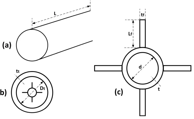
transfer system configuration was identified and adopted for the high-pressure scenario. It is
171
comprised of a series of MH material filled tubes. Finned mini-channel cylindrical tubes, located
172
inside the MH tube, provide the required cooling/heating power to charge/discharge the hydrogen.
173
The frontal 2D view of a single tube is shown in Figure 2. The proposed system has several
174
advantages over more traditional heat transfer systems with the heat transfer fluid flowing in the
175
shell side of the component. The wall of the MH tube, in general, can be very thick, given the current
176
operating pressure conditions of 875 bar. Therefore, including an insulation layer between the MH
177
tube and the vessel wall, the proposed solution allows a direct heat exchange between the fluid and
178
the MH material. This avoids the presence of additional relevant thermal inertia represented by the
179
MH tube wall.
180
181
182
183
Figure 2. Single tube MH material heat transfer coupled system, showing: (a) Simplified external
184
view of a single MH tube; (b) 2D frontal view of the single tube with 4 fin internal mini-channel heat
185
transfer tube; (c) zoomed view of the internal finned minichannel heat transfer fluid tube.
186
187
The steady state heat transfer energy balance equation during hydrogen absorption, using the
188
Log Mean Temperature Difference (LMTD) approach, is expressed as:
189
̇ ( − ) = ℎ −−
−
(7)
The steady state heat transfer energy balance equation during hydrogen desorption, using the
190
LMTD approach, is expressed as:
̇ ( − ) = ℎ −−
− (8)
Constant steady state temperatures during absorption and desorption were assumed. The heat
192
transfer coefficient, accounts for the conductive heat transfer process inside the MH material and the
193
convective laminar heat transfer in the fluid. The overall heat transfer coefficient under laminar
194
conditions can be assessed from Equation 9:
195
1
ℎ= 2 +4.66 (9)
with kHF and kMH (W/m-K) being the thermal conductivity of the heat transfer fluid and of the
196
metal hydride material respectively.
197
Equation 9 was derived assuming that the thickness of the heat transfer tubes (t) is negligible
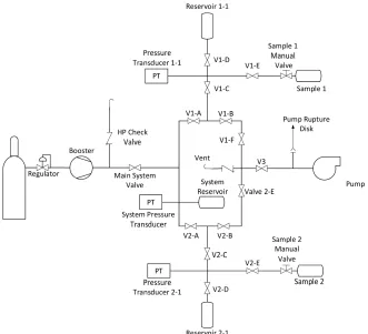
198
and that Nu = 4.66 for the heat transfer fluid under laminar flow conditions [8].
199
The heat transfer surface area of the heat exchanger is:
200
= max ( , ) (10)
The mass of the tubing walls is estimated based on the adopted heat transfer configuration as
201
well as on the operating conditions, as discussed in the next sections.
202
The conceptual design of the material heat exchanger coupled system was carried out based on
203
the geometrical constraints, defined by the heat transfer requirements and the volume occupied by
204
the MH material. The required heat transfer surface area (S) and the volume (V) occupied by the MH
205
material are expressed in Equations 11 and 12:
206
= + (11)
= =
4 − 4 (12)
with NT and nf being the overall number of tubes and the number of fins per tube, respectively.
207
Equations 11 and 12 were derived assuming the thickness of the internal heat transfer tubes (t)
208
and of the fins (tf) are reasonably negligible compared to the other dimensions.
209
3.2. Metal hydride compressor system economic model
210
The installed cost of the MH system was assessed adopting a traditional factored methodology.
211
By this approach the installed cost can be evaluated as the Free on Board (FOB) component cost with
212
additional installation costs, computed using installation factors, as expressed in Equation 13:
213
= (13)
The installation factor (finst) accounts for the cost of connecting tubing and piping, external
214
insulation, painting, electrical and control equipment, labor, concrete, etc. It also accounts for the
215
high-pressure distribution plates for hydrogen and low-pressure connections for the heat transfer
216
fluid. The values were assessed adopting traditional equipment databases and process modeling
217
programs, namely ASPEN In plant Cost Estimator® [9].
218
The component FOB cost is expressed as follows:
219
= + (14)
The first term (CMH) represents the FOB cost of the MH material. It includes the cost of the raw
220
material, the manufacturing, processing and heat treatment cost and the cost for handling and
221
locating the material inside the tank. This term was assessed based on industrial material data from
222
JMC Alloy [10], for the different selected alloys. The second term (CHEPV) is the FOB cost of the MH
223
tubes and heat exchanger tubing (i.e. finned tubes cost) placed inside the MH tube. The cost of the
224
internal heat transfer tubes was assessed based on industrial tubing values [11], with Al considered
as the constitutive material of the heat transfer tubes. The cost of the MH tubes was assessed based
226
on industrial Swagelok ‘Super Duplex’ tubing catalogs and from personal communications with
227
Swagelok [12], with SS2507 considered as the constitutive material of MH tubes, operating in a
228
hydrogen environment up to pressures of 900 bar.
229
4. Results
230
The techno-economic model was applied to different MH, which were then downselected based
231
upon constraints and initial degrees of freedom assumed on the basis of the compressor configuration
232
and operating conditions. The performance of the selected MHC systems was assessed and
233
compared, showing the potential of selected materials to achieve the required operating conditions.
234
4.1. Initial downselected materials
235
To carry out the techno-economic analysis the following assumptions were made. The hydrogen
236
flow rate is between 1 kg/h (for smaller scale applications) and 100 kg/h (for large scale scenarios)
237
based on the DOE targets [1]. With reference to Figure 1, the inlet hydrogen pressure (PH1) is equal to
238
100 bar, achieved at the exit of the electrochemical stage [3]. The MHC system operates with a
239
compression ratio of 8.75, compressing the hydrogen up to 875 bar, as required by the DOE targets.
240
The MHC system is also assumed to be comprised of a single stage MH compressor, in order to
241
reduce the investment cost and the plant management complexity required by two or multiple stage
242
MH compressors. The MH heating power, required to desorb the hydrogen, is assumed to be
243
provided as waste heat from the EHC at THH1 = 155 °C. The MH cooling power, required to absorb the
244
hydrogen, is assumed to be provided by a cooling source at TCH1 = 15 °C. Each of the two MHC system
245
lines (operating in opposite charging/discharging phase) was assumed to be comprised of two MH
246
units operating in parallel, to assure continuity of exercise during possible maintenance or failure of
247
one unit. Some of the degrees of freedom of the problem were assumed ab initio limiting the number
248
of the unknows of the overall problem. The charging/discharging time of the MHC was assumed
249
equal to 10 min (i.e. 20 min per each complete cycle), with absence of material weight capacity
250
degradation for (at least) 35,000 cycles. Existing AB2 MH materials have the right characteristics to
251
achieve the required cycling time (i.e. fast kinetics) and degradation performance [13]. Depending on
252
the formulation, the AB2 MH material operating pressures can range between 10 bar and over 1000
253
bar. A comprehensive list of existing AB2 materials for hydrogen compression applications, both for
254
low and high pressures, can be found in Reference [2]. However, the temperature constraint of the
255
proposed scenario limits the available existing AB2 metal hydrides to only a few possible candidates.
256
A first screening of the existing AB2 materials was carried out, based on the available databases and
257
literature data [14,2] and depending on the operating conditions (temperatures and pressures). Four
258
candidate materials were preliminary screened, with their thermodynamic and physical and
259
chemical properties shown in Tables 1-2.
260
The thermodynamic and weight capacity data for the HP1 material (TiCr1.9) were collected from
261
References [15,16]. The corresponding equilibrium operating conditions were estimated using the
262
van’t Hoff equation.
263
Table 1. Thermodynamic properties, weight capacity and equilibrium conditions of the four
264
downselected high pressure metal hydrides (HP1, HP2, HP3, HP4).
265
Material Habs/Hdes (kJ/molH2)
Sabs/Sdes (kJ/molH2)
wt (%)
Equilibrium P (bar)/ T (°C)
HP1: TiCr1.9 26.2 122.0 1.4 100/40 - 875/125
HP2: (Ti0.97Zr0.03)1.1Cr1.6Mn0.4 23.4 115.0 1.7 100/32 - 875/125
HP3: Ti1.1CrMn 22.9 114.7 1.5 100/27 - 875/119
HP4: TiCrMn0.4Fe0.4V0.2 20.2/22.0 103.0/109.0 1.9 100/39 - 875/145
Table 2. Chemical and physical properties of the four downselected high pressure metal hydrides
267
(HP1, HP2, HP3, HP4).
268
Material bulk
(kg/m3)
kMH (W/m-K)
CpMH (J/kg-K)
HP1: TiCr1.9 3130 8.0 486
HP2: (Ti0.97Zr0.03)1.1Cr1.6Mn0.4 3140 8.0 485
HP3: Ti1.1CrMn 3170 8.0 493
HP4: TiCrMn0.4Fe0.4V0.2 3170 8.0 491
269
The HP1 material is characterized by significant hysteresis and sloped plateaus at the
270
temperature and pressure range of interest [15,3,17]. Even if the material is characterized by excellent
271
operating pressures and temperatures, it cannot be adopted for an effective high-pressure hydrogen
272
compression system. However, the material was still included as possible candidate material,
273
accounting for possible future material development and modifications to achieve enhanced
274
performance. The HP2 material ((Ti0.97Zr0.03)1.1Cr1.6Mn0.4) is characterized by flatter plateau profiles
275
and reduced material hysteresis [18]. The thermodynamic and weight capacity data for the HP2
276
material have been collected from Reference [18], with the corresponding equilibrium operating T
277
and P estimated using the van’t Hoff equation. Likewise, the HP3 material (Ti1.1CrMn) properties
278
have been assessed based on the data available in Reference [19]. The main limit of the HP3 material
279
is the absorption temperature, required to be on the order of 27 °C for 100 bar. The reduced
280
temperature differences in the heat transfer cooling system makes the design of the heat exchanger
281
more challenging, requiring additional finned structures and higher heat transfer fluid flow rates.
282
The HP4 material thermodynamic properties and weight capacity were collected from Reference [20].
283
The HP4 material was still included as potential candidate, but is characterized by an operating
284
temperature (145 °C) very close to the hot utility temperature (155 °C), with an overall temperature
285
difference of only 10 °C.
286
The bulk density was estimated based on the crystal density and assuming a void fraction of
287
50%. Expansion and contraction of the material during absorption and desorption was assumed equal
288
to 15% of the initial volume under totally desorbed state [2]. The thermal conductivity value was
289
assessed based on the data and information available in References [21-23]. Thermal conductivity
290
values on the order of 5-10 W/m-K are reported when expanded natural graphite is mixed with the
291
material in quantities on the order of about 10wt%. The specific heat values were estimated based on
292
the material formulation, resulting in values on the order of 500 J/kg-K for each material.
293
4.2. Technical analysis results
294
The technical feasibility and the corresponding performance of the MH systems comprised of
295
the four downselected alloys are described and discussed in the following sections.
296
The technical analysis was carried out under the following assumptions. Two scenarios were
297
analyzed: the first scenario saw the adoption of MH compressors for small scale applications (1
298
kgH2/h, with pressures 100-875 bar), the second scenario was for large scale applications (100 kgH2/h,
299
with pressures 100-875 bar). Given the high-pressure range, only small diameter metal tubes are
300
currently available. The MH tube diameter (Dt) was assumed equal to 1.3 cm, which is the available
301
diameter from Swagelok catalogs, with SS2507 as the constitutive material. The corresponding wall
302
thickness (tt) was estimated equal to 2.1 mm. This confirms that the optimal heat transfer solution is
303
to include minichannel tubes internally in the MH tubes. Finned aluminum tubes were adopted to
304
transfer the cooling/heating power, with diameter (d) of 2.4 mm. Pressurized water (at pressures of
305
7.5 bar) was assumed as the heat transfer fluid.
306
Results in Tables 3 highlight the heating/cooling power required to desorb/absorb hydrogen for
307
100 kg/h. The contributions of sensible heating/cooling, to vary the operating temperature of the MH
308
bed, and latent heating/cooling required by the chemical reaction (i.e. desorption and absorption
309
respectively) are also shown in the table.
Table 3. Heating and cooling power duty of the four downselected high pressure metal hydrides
311
(HP1, HP2, HP3, HP4) processing 100 kg/h.
312
Material Sensible power (kW) [100 kgH2/h]
Reaction power (kW) [100 kgH2/h]
Total power (kW) [100 kgH2/h]
HP1: TiCr1.9 130.8 366.8 497.6
HP2: (Ti0.97Zr0.03)1.1Cr1.6Mn0.4 117.4 327.6 445.0
HP3: Ti1.1CrMn 139.2 320.6 459.8
HP4: TiCrMn0.4Fe0.4V0.2 127.51 308.01 435.51
1 The values refer to the desorption phase, which is the most challenging due to the reduced
313
LMTD.
314
315
Table 4 shows the results of a first conceptual design of the 4 selected systems.
316
Table 4. Conceptual design results of the four downselected high pressure metal hydrides (HP1,
317
HP2, HP3, HP4) processing 1 kg/h and 100 kg/h. Each system is comprised of 4 parallel units
318
Material Number of tubes1 [1 kg/h - 100 kg/h]
Number of fins2 [1 kg/h - 100 kg/h]
Length, L1 (m) [1 kg/h - 100 kg/h]
Water flow1 (g/s) [1 kg/h - 100 kg/h]
HP1: TiCr1.9 15 - 1474 4 - 4 1.60 – 1.55 28.7 - 2866
HP2:
(Ti0.97Zr0.03)1.1Cr1.6Mn0.4 16 - 1550 4 - 4 1.20 – 1.20 51.3 - 5127
HP3: Ti1.1CrMn 14 - 1444 8 - 8 1.60 – 1.50 53.0 – 5297
HP4:
TiCrMn0.4Fe0.4V0.2 14 - 1565 10 - 10 1.30 – 1.20 62.7 - 6271
1 per each unit (the system has 4 units)
319
2 per each tube
320
321
The system design essentially follows a linear relationship with the hydrogen flow rate, from 1
322
kg/h to 100 kg/h. The sensible heating/cooling power required to increase/decrease the operating
323
temperature plays an important role in the technical performance of the MHC system, contributing
324
for about 26-30% of the overall required thermal power. The reduced temperature differences in the
325
HP4 compressor between the MH and the heat transfer fluid, during the desorption phase (LMTD =
326
6 °C) results in increased heat transfer surface area (i.e. increase of the number of fins required to
327
transfer the heat during the desorption). Even if the HP4 system requires the lowest heating power
328
(approximately 2% lower than the HP2 material), the reduced LMTD value has also the effect of
329
requiring higher water flow rates (about 22% higher than the corresponding HP2 system) to maintain
330
the heat exchange feasible (temperature pinch point equal to 2 °C).
331
4.3. Economic analysis results
332
The economic feasibility and performance of the proposed compression systems are described
333
below. The analysis was carried out using Year 2017 US $. The installation factor, described in Section
334
3, was estimated adopting ASPEN In Plant Cost Estimator and including additional feasible
335
estimations for the distribution plates. The installation factor values were equal to 1.35 for the
large-336
scale scenario (100 kg/h) and 7.0 for the small-scale scenario (1kg/h).
337
Results of the small-scale (1 kg/h) and large-scale scenarios (100 kg/h) are shown in Figures 3-4,
338
respectively, highlighting the influence of the MH material cost and the heat exchanger and tubing
339
cost.
342
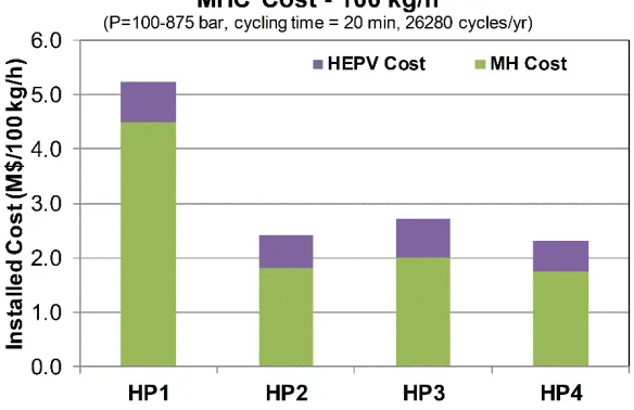
Figure 3. Installed cost of the MHC system for small scale scenarios (i.e. 1 kgH2/h)
343
344
345
Figure 4. Installed cost of the MHC system for large scale scenarios (i.e. 100 kgH2/h)
346
347
The cost of the MH material is directly proportional with the hydrogen flow rate, as for each
348
modular system. The heat exchanger and tubing cost, along with the additional installation costs,
349
follows a power law with regard to the hydrogen flow rate. The HP1 is the most expensive system,
350
mainly due to the MH material cost. For the small-scale scenario, the material cost accounts for about
351
60% of the overall installed cost. This contribution goes up to about 86% for the large-scale scenario.
352
The HP2 material represents the best option among the selected materials adopted in high pressure
353
systems. For the small-scale scenario the HP2 material cost accounts for about 39% of the overall
354
installed cost, achieving about 75% for the large-scale scenario. The HP3 and HP4 systems have
355
similar performance with the HP2 compressor. The HP3 material cost accounts for about 40% of the
356
overall installed cost for small scale conditions, reaching about 74% for the corresponding large-scale
357
scenario. The HP4 system shows an economic performance essentially identical with the HP2
358
material. The HP4 material cost influence on the overall small-scale scenario cost is about 40%,
359
reaching values of almost 76% for large scale scenarios.
360
Cost sensitivity analyses were also carried out for the best candidate material (HP2) at large scale
361
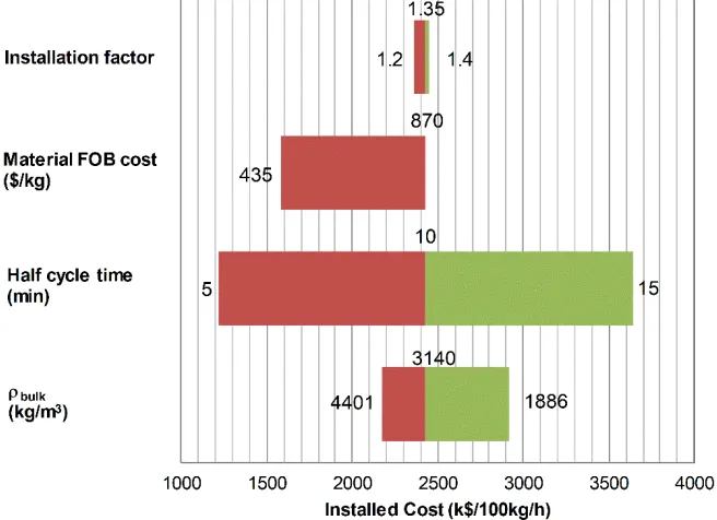
scenarios. The sensitivity analysis ‘tornado chart’ is shown in Figure 5. Four techno-economic
362
parameters (density, cycle time, material cost and installation cost) were chosen as the most
363
significant quantities.
365
Figure 5. Tornado chart cost sensitivity for the large scale (100 kg/h) HP2 system
366
367
Each parameter was varied maintaining constant the other quantities. The heat exchanger
368
system geometry was a fixed parameter for the current sensitivity analysis. The material intrinsic
369
properties (e.g. reaction enthalpy, weight capacity, specific heat, overall thermal conductivity) were
370
also assumed fixed, since their variation would require additional material development and
371
analysis. The bulk material density varied between 30% of the crystal density (i.e. 1886 kg/m3) and
372
70% of the crystal density (i.e. 4401 kg/m3), assuming a different degree of compaction. The baseline
373
bulk density is equal to 3140 kg/m3, or 50% of the crystal density. The corresponding system cost saw
374
a variation of + 34% with the decrease of the bulk density of about 40% compared to the baseline
375
value. This is also due to presence of additional void space, which reduces the volumetric efficiency
376
of the compressor, resulting in additional metal hydride material to be included in the system. The
377
cycling time is the quantity that showed the highest influence on the overall system cost. A variation
378
of the cycle time of ±50% results in a corresponding cost variation of ±50%, reaching values of about
379
$3.6M for a cycling time of 30 min. A relevant influence on the system cost was also noticed for the
380
MH FOB cost. A reduction of the FOB cost of 50% (i.e. equal to 435 $/kg) resulted in a reduction of
381
the system cost of almost 35%, reaching a value of about $1.6M. The influence of the installation factor
382
on the installed cost was very limited compared to the sensitivity of the other quantities. A reduction
383
of the installation factor from 1.35 (baseline value) to 1.2 resulted in a reduction of the installed cost
384
of approximately 2.7%. The cost of heat exchanger, pressure vessel, distribution plates and
385
installation plays a more relevant role in the small scale scenario (1 kg/h), influencing the overall
386
installed cost for more than 50%.
387
5. Discussion and future work
388
Given the stringent constraints dictated by the operating conditions and the need for reduced
389
investment costs, only a few existing MH materials could be downselected as candidates for high
390
pressure MH compressors. Among the four downselected materials only one candidate (HP2
391
material) has high potential for application in the actual system. The HP1 material is limited by its
392
high slope of the two-phase region and relevant hysteresis, making the hydride not the best candidate
393
for compression applications. In addition, the limited weight capacity and high material cost of the
394
HP1 material result in significant increase of the investment cost compared with the other candidate
395
materials. The HP3 and HP4 materials suffer from the heat transfer management required to achieve
396
pressures between 100 bar and 875 bar. The HP3 hydride requires temperatures lower than 27 °C to
absorb hydrogen at 100 bar making the heat transfer with external cold utility fluid (at 15 °C)
398
challenging. The HP4 material requires temperatures close to 150 °C to desorb hydrogen at 875 bar
399
making the recovery of the available waste heat from the EHC system challenging. The HP2 material
400
will be verified in terms of operating pressures and temperatures at industrial level.
401
To experimentally evaluate the candidate materials a high-pressure Sieverts’ apparatus, reaching
402
pressures > 900 bar, would be designed and built (Figure 6). The system will employ a 2-channel
403
design as to optimize MH characterization. All components will be rated at pressures >1000 bar with
404
minimal volume tubing used to ensure limited dead volume existed between reservoirs and sample
405
holders. The system would be controlled by pneumatically driven valves and regulator allowing for
406
the availability of full automation, thereby, permitting data collection of isothermal, kinetic and
407
cycling measurements. Laboratory cylinder hydrogen would be fed to a flammable gas compressor
408
allowing for the necessary pressures to be achieved for testing. The system would store the
409
compressed hydrogen in a 60-70 ml high-pressure storage container in preparation for aliquots of gas
410
to be absorbed by the sample. The storage reservoir, as well as the channels’ reservoirs, would be
411
contained within a temperature-controlled frame. The sample holders would be external from the
412
fame and could be heated or chilled to temperatures ranging from less than -10 to greater than 150
413
°C. The sample holders chosen would allow for amounts of material >25 g to be tested at a time.
414
Designing the system around large quantities of samples to be measured permits the examination of
415
a prototype-scale level of characterization.
416
417
418
Figure 6. Schematic rendering of a 2-channel high-pressure Sieverts’ apparatus for characterization
419
of prototype-scale metal hydride materials.
420
6. Conclusions
421
A novel techno-economic analysis model was developed, including steady state mass and
422
energy balance equations, and applied to high-pressure MH thermal compressors. Technical and
423
economic performance of MH systems, compressing hydrogen from 100 bar to 875 bar with heating
424
power provided at temperatures on the order of 150 °C, was assessed. The system was assumed to
425
be coupled with an electrochemical system, which provides the heating power (waste heat from the
426
electrochemical component) required to desorb hydrogen from the metal hydride system. A novel
heat transfer system is also proposed to exchange the heating and cooling power with the metal
428
hydride material. The configuration sees the adoption of finned minichannel heat transfer tubes
429
placed inside the MH material tubes, allowing for enhanced technical performance compared to
430
traditional shell and tube solutions. Only a few metal hydride materials could be initially
431
downselected, being able to achieve the required operating conditions (pressures and temperatures).
432
Results showed that the novel heat transfer system allowed all the downselected materials to
433
potentially achieve the operating pressure (875 bar) at temperatures lower than 150 °C. However only
434
one of the selected alloys, namely (Ti0.97Zr0.03)1.1Cr1.6Mn0.4 showed more realistic temperature
435
differences in the heat transfer process, making it the best candidate for the proposed application.
436
Cost results, obtained for currently available materials at industrial level for quantities on the order
437
of 10-50 kg, showed the economic feasibility of the proposed system. Economic sensitivity analyses
438
were also carried out, showing different approaches to enhance the economic performance. The
439
overall system cost can be reduced up to about 50% of the initial cost with a reduction of the material
440
cost of 50% and an increase of the bulk density up to 70% of the crystal density.
441
442
Author Contributions: The authors contributed as follows: Conceptualization, methodology and results C.C.;
443
Future work, Writing-Review & Editing, M.S.
444
Funding: The work was carried out under the U.S. Department of Energy Award Number DE-EE0007648.
445
Acknowledgments: The authors wish to acknowledge Drs. Neha Rustagi, James Vickers and Eric Miller, who
446
are the U.S. Department of Energy managers, for financial support as well as for providing useful comments
447
and direction during the current work. The authors also wish to thank Dr. Robert Bowman Jr. for his insights,
448
help and discussions.
449
The views and opinions of the authors expressed herein do not necessarily state or reflect those of the United
450
States Government or any agency thereof. Neither the United States Government nor any agency thereof, nor
451
any of their employees, makes any warranty, expressed or implied, or assumes any legal liability or
452
responsibility for the accuracy, completeness, or usefulness of any information, apparatus, product, or process
453
disclosed, or represents that its use would not infringe privately owned rights.
454
Conflicts of Interest: The authors declare no conflict of interest.
455
References
456
1. U.S. Department of Energy Fuel Cell Technologies Office Multi-Year Research, Development and
457
Demonstration Plan - 3.2 Hydrogen Delivery, 2015.
458
https://www.energy.gov/sites/prod/files/2015/08/f25/fcto_myrdd_delivery.pdf (Accessed March
459
2018).
460
2. Lototskyy, M.V.; Yartys, V.A.; Pollet, B.G.; Bowman, R.C. Metal hydride hydrogen compressors: A
461
review. Int J Hydrogen Energy 2014, 39(11), 5818-5851.
462
3. Corgnale, C.; Greenway, S.; Motyka, T.; Sulic, M.; Hardy, B.; Molter, T. et al. Technical performance
463
of a hybrid thermo-electrochemical system for high pressure hydrogen compression. ECS
464
Transactions 2017, 80(10), 41-54.
465
4. Hattrick-Simpers, J.; Choudhary, K.; Corgnale, C. A simple constrained machine learning model
466
for predicting high-pressure-hydrogen-compressor materials. Mol Syst Des Eng 2018,
467
10.1039/C8ME00005K, Advance article.
468
5. Gkanas, E.I.; Grant, D.M.; Stuart, A.D.; Eastwick, C.N.; Book, D.; Nayebossadri, S.; et al. Numerical
469
Study on a Two-Stage Metal Hydride Hydrogen Compression System. J Alloy Compd 2015, 645(1),
470
S18-S22.
471
6. Karagiorgis, G.; Christodoulou, C.N.; von Storch, H.; Tzamalis, G.; Deligiannis, K.; Hadjipetrou,
472
D.; et al. Design, development, construction and operation of a novel metal hydride compressor. Int
473
J Hydrogen Energy 2017,42(17),12364-12374.
474
7. Galvis, A.R.; Leardini, F.; Ares, J.R.; Cuevas, F.; Fernandez, J.F. Simulation and design of a
three-475
stage metal hydride hydrogen compressor based on experimental thermodynamic data. Int J
476
Hydrogen Energy 2018,43, 6666-6676.
8. Shah, R.K.; London, A.L. Laminar Flow Forced Convection in Ducts, Supplement 1 to Advances in
478
Heat Transfer; Acedemic, New York, 1978.
479
9. Aspen In Plant Cost Estimator. ASPEN Tech Manual. Available at
480
https://www.aspentech.com/en/products/pages/aspen-in-plant-cost-estimator (Accessed May 2018) .
481
10. JMC Alloy. Personal Communication. 2017.
482
11. Grainger catalog. Available at
https://www.grainger.com/category/aluminum-483
tubing/tubing/pipe-tubing-and-fittings/plumbing/ecatalog/N-qwo (Accessed May 2018).
484
12. Swagelok catalog. Available at
https://www.swagelok.com/downloads/webcatalogs/EN/MS-01-485
174.PDF (Accessed May 2018).
486
13. Friedlmeier, G.; Manthey, A.; Wanner, M.; Groll, M. Cyclic stability of various
application-487
relevant metal hydrides. J Alloy Compd 1995, 231(1-2), 880-887.
488
14. Hydrogen Storage Materials Database http://hydrogenmaterialssearch.govtools.us/search.aspx
489
(Accessed March 2018).
490
15. Johnson, J.R.; Reilly, J.J.; Reidinger, F.; Corliss, L.M.; Hastings, J.M. On the existence of f.c.c.
491
TiCr1.8H5.3. Journal of the Less Common Metals 1982, 88(1), 107-114.
492
16. Beeri, O.; Cohen, D.; Gavra, Z.; Mintz, M.H. Sites occupation and thermodynamic properties of
493
the TiCr2-xMnx-H2 (0≤x≤1) system: Statistical thermodynamics analysis. J Alloy Compd 2003, 1-2,
494
111-122.
495
17. Corgnale, C.; Hattrick-Simpers, J.; Sulic, M.; Weidner, J.; Lopata, J. Experimental assessment of
496
thin film high pressure metal hydride material properties. Int J Hydrogen Energy 2018, under review.
497
18. Wang, X.; Chen, R.; Zhang, Y.; Chen, C.; Wang, Q. Hydrogen storage alloys for high-pressure
498
suprapure hydrogen compressor. J Alloy Compd 2006, 420, 322-325.
499
19. Cao, Z.; Ouyang, L.; Wang, H.; Liu, J.; Sun, D.; Zhang, Q. Advanced high-pressure metal hydride
500
fabricated via Ti-Cr-Mn alloys for hybrid tank. Int J Hydrogen Energy 2015, 40, 2717-2728.
501
20. Vanhanen, J.P.; Hagstrom, M.T.; Lund, P.D. Combined hydrogen compressing and heat
502
transforming through metal hydrides. Int J Hydrogen Energy 1999, 24, 441-448.
503
21. Pasini, JM.; Corgnale, C.; van Hassel, B.; Motyka, T.; Kumar, S.; Simmons, K. Metal hydride
504
material requirements for automotive hydrogen storage systems. Int J Hydrogen Energy 2013, 38,
505
9755-9765.
506
22. Corgnale, C.; Hardy, B.J.; Tamburello, D.A.; Garrison, S.L.; Anton, D.L. Acceptability envelope for
507
metal hydride-based hydrogen storage systems. Int J Hydrogen Energy 2012, 37(3), 2812-2824.
508
23. Corgnale, C.; Motyka, T.; Greenway, S.; Perez-Berrios, J.; Nakano, A.; Ito, I. Metal hydride bed
509
system model for renewable source driven Regenerative Fuel Cell. J Alloy Compd 2013, 580(1),
S406-510
S409.
511
24. Guo, X.; Wang, S.; Liu, X.; Li, Z.; Lu, F.; Mi, J. et al. Laves phase hydrogen storage alloys for
super-512
high-pressure metal hydride hydrogen compressors. Rare Metals 2011,30(3),227-231.
513
Nomenclature
514
C Cost ($)
515
Cinst Installed cost ($)
516
CP Specific heat (kJ/kg-K)
517
DOE U.S. Department of Energy
518
EHC Electrochemical hydrogen compressor
519
finst Cost installation factor
520
FOB Free on board
521
h Specific enthalpy (kJ/kg), or heat trasnfer coefficient (W/m2-K)
522
k Thermal conductivity (W/m-K)
523
LMTD Log mean temperature difference
524
̇ Mass flow rate (kg/s)
525
M Mass (kg)
526
MH Metal hydride
527
MHC Metal hydride hydrogen compressor
528
nf Number of fins per tube
NT Number of tubes
530
P Equilibrium pressure (bar)
531
R Gas constant (8.314 J/mol-K)
532
S Heat transfer surface area (m2)
533
V Volume (m3)
534
wt Weight capacity (kgH2/kgMH)
535
536
Greek letters
537
H Reaction enthalpy (kJ/molH2 or kJ/kgH2)
538
S Reaction enthalpy (kJ/molH2-K or kJ/kgH2-K)
539
t Time (s)
540
ηv Volumetric efficiency
541
ρ Density (kg/m3)
542
543
Subsript
544
abs Absorption
545
bulk Bulk
546
CH Cold utility
547
des Desorption
548
HEPV Heat exchanger and pressure vessel
549
HF Heat transfer fluid
550
HH Hot utility
551
MH Metal hydride
552