Mech. Sci., 3, 15–23, 2012 www.mech-sci.net/3/15/2012/ doi:10.5194/ms-3-15-2012
©Author(s) 2012. CC Attribution 3.0 License.
Mechanical
Sciences
Open Access
Building block method: a bottom-up modular synthesis
methodology for distributed compliant mechanisms
G. Krishnan1, C. Kim2, and S. Kota3
1Mechanical Engineering, University of Michigan, Ann Arbor, MI 48105, USA 2Mechanical Engineering, Bucknell University, Lewisburg, PA 17837, USA
3Department of Mechanical Engineering, University of Michigan, Ann Arbor, MI 48105, USA
Correspondence to: G. Krishnan ([email protected])
Received: 19 March 2011 – Revised: 31 January 2012 – Accepted: 2 March 2012 – Published: 28 March 2012
Abstract. Synthesizing topologies of compliant mechanisms are based on rigid-link kinematic designs or completely automated optimization techniques. These designs yield mechanisms that match the kinematic specifications as a whole, but seldom yield user insight on how each constituent member contributes towards the overall mechanism performance. This paper reviews recent developments in building block based design of compliant mechanisms. A key aspect of such a methodology is formulating a representation of compliance at a (i) single unique point of interest in terms of geometric quantities such as ellipses and vectors, and (ii) rel-ative compliance between distinct input(s) and output(s) in terms of load flow. This geometric representation provides a direct mapping between the mechanism geometry and their behavior, and is used to characterize simple deformable members that form a library of building blocks. The design space spanned by the building block library guides the decomposition of a given problem specification into tractable sub-problems that can be each solved from an entry in the library. The effectiveness of this geometric representation aids user insight in design, and enables discovery of trends and guidelines to obtain practical conceptual designs.
1 Introduction
Kinematics of conventional rigid-link mechanisms and their systematic synthesis has been studied for almost a couple of centuries (Erdman et al., 2001). This has resulted in a database of a number of tried and tested mechanisms, each adept in a specific task (Sclater and Chironis, 2007). A de-signer can either choose an existing conceptual design from the database, or systematically combine a number of designs to meet a more complex specification. Once the conceptual design is chosen, it can be refined for the application at hand by first analyzing the various geometrical configurations that rigid links and kinematic pairs assume, and then analyzing forces in links to determine the amount of material required to maintain strength and rigidity. For most applications mul-tiple solutions can be generated, and secondary criteria such as aesthetics and ergonomics can be used to determine the best solution. The simplicity of this process is as a result of the decoupling between kinematic and structural aspects of design.
In the past couple of decades researchers are interested in monolithic mechanisms devoid of joints and links that de-rive their mobility on elastic deformation alone. They have significant advantages that are well documented in literature such as elimination of friction, backlash and reduced manu-facturing costs by avoiding assembly (Howell, 2001). Fur-thermore, their versatility is increased by their scalability in various length scales. However, elastic deformation may lead to material failure at certain regions having high stresses thus limiting range of motion and the load carrying ability of these mechanisms. The main design challenge for compli-ant mechanisms is the intricate coupling between kinematics and elasticity. In other words, the topology of a mechanism and the size of its individual elements together determine how the mechanism moves and the internal forces within its members, thus precluding synthesis akin to rigid-link mech-anisms.
As a first attempt at design, Howell and Midha used conventional rigid-link topologies and the associated design methodologies to first design a rigid-link mechanism that
with beams of equivalent length to match the required kine-matics. The cross-section of the beams were then deter-mined based on the stiffness of the torsional springs and the stress considerations. This technique where an equivalent rigid link and a torsional spring is used to analyze and de-sign monolithic elastic mechanisms is known as pseudo-rigid body model. The designs that resulted from this methodol-ogy, though practical yield distinct areas where flexibility is lumped. These are also the areas where stresses are concen-trated and thus limit lead bearing and large range of motions. Topology optimization was developed by Ananthasuresh (1994) that aimed at a better utilization of the design space without restricting to conventional topologies. This proce-dure initially lists all possible interconnections of beams or a planar finite element mesh of the design domain, whose widths or thickness are the design variables for optimization. Elements with the values of design variables lower than a specific cut-offwill not be considered to contribute towards the final topology. The optimization algorithm determines an optimal topology that maximizes an objective function. If the objective function defines the kinematic behavior of the mechanism alone, without incorporating strength consid-erations, the optimization yields mechanisms that are com-posed of rigid members and thin flexures (Saxena and Anan-thasuresh, 2003). Yin and Ananthasuresh (2003) and Can-field et al. (2007) have demonstrated the use of additional constraints that prevent large relative rotations between two finite elements that constitute the topology in the design do-main. Nevertheless, there is considerable complexity in in-corporating stress considerations in topology optimization. Furthermore, this process yields little insight on the func-tional contribution of different elements in the topology. Fur-thermore, the optimum connectivity may not be present in the design parametrization, which leads to suboptimal or convo-luted designs.
Thus, there is a need to understand the contributions of each member that constitutes the design. This understanding can yield insightful conceptual synthesis of compliant mech-anisms, where simple deformable members are systemati-cally combined to obtain the overall topology. Such a build-ing block method was proposed by Kim (2005); Kim et al. (2008).
2 Overview of building block methods
Complex systems such as an automobile, aircraft and elec-tronic gadgets are always broken down into simpler subsys-tems that can be easily designed. For example, an automobile consists of combustion, transmission, electrical subsystems all working together. These subsystems are designed and fab-ricated separately and integrated during assembly. A similar
Evaluation of Candidate Building Blocks
Problem Decomposition
Mechanism Assembly
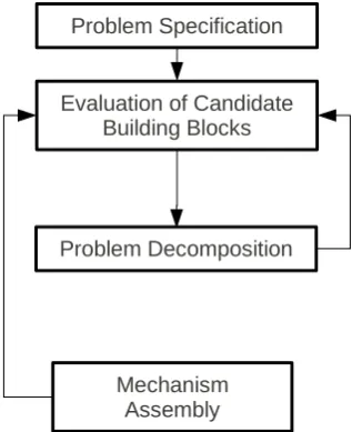
Figure 1.Schematic of the building block method for design.
building block approach was proposed for mechanism design by Kota and Chiou (1992) for conventional rigid link mech-anism synthesis. The building block method is captured in the flowchart shown in Fig. 1 (Kim, 2005). Once kinematic specifications were determined, they were compared with en-tries in the database of existing designs. If no entry is found, the problem specification is broken down to tractable sub-problems, whose solutions are found in the database. The final design is an assembly of the individual subproblems.
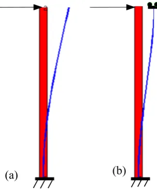
Building block methods are common in conceptual de-signs where there is a functional independence between the constituent building blocks. This means that when two build-ing blocks are combined, one does not change the inherent behavior of the other. For example, a slider joint remains a slider irrespective of the number of links attached to it. However, in domain specific design problems such as com-pliant mechanism synthesis, the deformation behavior of a building block is in general determined by rest of the topol-ogy. In other words the same building block may have two different deformation behaviors based on its loading condi-tion. Consider a simple cantilever beam that is ubiquitous in most compliant mechanism topologies. Its deformation behavior can range from fixed-free to fixed-guided based on loads acting on the free end as seen in Fig. 2. In most prob-lems this deformation behavior cannot be determined before hand. Is it then possible to use the elements of the building block method as shown in Fig. 1 for compliant mechanism synthesis?
The answer for the above question lies in the representa-tion of compliance that favors building block method. Such a representation must provide
G. Krishnan et al.: Building block method 17
(a)
(b)
Figure 2.A beam with an end load has different deformation pro-files when its end is (a) free, or (b) guided (constrained rotation and axial motion). Whether it behaves as (a) or (b), or between the two in a compliant mechanism depends on the subsequent members attached to it.
compliance. Furthermore the representation must be intrinsic to the topology and independent of reference frames used to evaluate it.
2. Parametric characterization: simple deformable build-ing blocks are characterized with changbuild-ing geometric parameters to span the design space. Use of geomet-ric quantities enable visualization of the tractable design space.
3. Systematic decomposition of problem into tractable subproblems: the compliance representation must pro-vide user insight in problem decomposition.
4. Enabling seamless assembly: the physics must enable seamless integration of the subproblems into the final solution.
There have been efforts in the past decade to propose var-ious representations that permit a building block approach. At a single point of interest the compliance matrix has been characterized as a three dimensional ellipsoid (Kim et al., 2008; Kim, 2005). This representation enabled designing mechanisms with a given stiffness behavior by parallel com-bination of curved beams and dyads (series comcom-bination of beams). Design for single-input single output mechanisms have been similarly proposed based on combining a num-ber of single point mechanisms between an input and output. Though these techniques yield conceptual designs that meet kinematic specifications, the representation lacks mathemat-ical rigor and thus yields limited insight in the process of combining building blocks. This paper reviews recent ad-vances in proposing a physically insightful, mathematically
β+δ
e
f1e
f2δ
r
ECoE
Input
f
xf
ym
Figure 3.Eigen-twist and Eigen-wrench parameters for a particular building block geometry.
robust compliance representation at a single point of interest (Krishnan et al., 2011) and relative compliance between two points (Krishnan et al., 2010).
3 Single port compliance: eigen-twist and eigen-wrench characterization
Single port compliance involves characterizing the force dis-placement relationship at a single point of interest. This is of importance in the design of constraints (Awtar et al., 2007), suspensions for microsystems, and elastic vision based sen-sors (Cappelleri, 2008). This force displacement relation-ship is given by the compliance matrix (or its inverse stiff -ness matrix). The dimensions of the compliance matrix in planar two dimensional case is 3×3. The three degrees of freedom are two translations in the plane of the geometry and a rotation about an axis perpendicular to the plane. The terms in the compliance matrix thus consist of both transla-tional and rotatransla-tional terms having different dimensions. To avoid dimensional inconsistencies, it is desired that transla-tions and rotatransla-tions are dealt with separately. This is accom-plished by shifting the point of interest from the input to a new point where decoupling translational and rotation terms of the compliance is possible (Lipkin and Patterson, 1992). This point, known as the Center of Elasticity (CoE) and is al-ways unique for a planar geometry Kim (2008) and is shown for a compliant dyad in Fig. 3. This point is similar to the remote center of compliance (RCC) in robotics, and the well established concepts of center of stiffness or center of com-pliance (Ciblak and Lipkin, 2003) as defined for a planar ge-ometry. If a rigid connection is established between the CoE and the input, then any force applied at this point yields pure translation, and any moment applied yields a pure rotation. Thus the translational compliance at this point can be repre-sented by an ellipse whose semi-major and semi-minor axes (af1 and af2) denote the primary and secondary compliance
directions. In these directions (ef1and ef2), any force applied
18 G. Krishnan et al.: Building block method
and a stiffness coupling vector as seen in Fig. 5. Further
in-sight into this characterization can be obtained in Krishnan
et al. [11].
δ
-1500 -500 0 1000 2000 -1500 -500 0 500 1500
a
f1a
f2 -100 0 100β+δ
-150 -50 0 50 150
0
β+δ
r
E2/k
gr
E/k
gC11 C12 C13
C12 C22 C23
C13 C23 C33
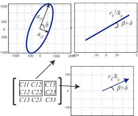
Fig. 4. Compliance ellipse and Compliance coupling vector (
~
c
v).-1000 -500 0 500 1000 -1000 -500 0 500 1000
1/a
f11/a
f2δ
-100 -50 0 50 100
-100 -50 0 50 100
β+δ+γ
s
cS11 S12 S13
S12 S22 S23
S13 S23 S33
Fig. 5. Stiffness ellipse and Stiffness coupling vector (
~
s
c).This representation of compliance easily sets stage for
a systematic building block based synthesis method. The
first stage for the building block method after determining
the problem specification is evaluation of candidate
build-ing blocks, or developbuild-ing a library of buildbuild-ing blocks. The
most versatile building block for compliant mechanism
syn-thesis is shown to be a series combination of two beams, as
a number topologies are shown to be composed of them [8],
[12]. The eigen-twist and the eigen-wrench parameters can
be evaluated by varying the angle between the two beams
that make up the dyad and their relative lengths. Figure 6
plots
n
p=
a
f2/
a
f1for varying length ratios (radius of the
po-lar plot) and dyad angles
α
. This gives an indication of the
design space spanned by the dyad for
n
p. Similarly other
210
240
270
300
330
1 1.5 2 130
150
180
0
0.01 0.4 0.5 0.6 0.5α
l
1radius: l
2normangle : α
11.5 2
Fig. 6. Parametric characterization of a compliant dyad for its
eigen-twist and eigen-wrench parameters. The figure shows one such plot adapted from [11].
Consider an example where equal biaxial (
X
and
Y
)
stiffness is required at a point without any coupling
trans-lational and rotational terms. Such a specification is required
for a vision-based force sensor [18], where external applied
force can be evaluated by measuring the deformation of a
point. Such a problem specification requires a circular
com-pliance ellipse with zero coupling vector magnitude shown in
Fig. 7a. Comparing from the database of compliant dyads no
design matches these specifications [11]. Figure 7b-c and 8
illustrate achieving these specifications using series and
par-allel combination of dyads. In series combination, the
cou-pling vectors of individual building blocks add. Thus the
zero coupling vector specification can be achieved by
align-ing equal and opposite buildalign-ing block specifications. Since
the degenerate shift ellipse depends on the coupling vector
orientations alone, its magnitude can be evaluated and
sub-tracted from the required ellipse to obtain a net ellipse (Fig.
7b). Two dyads are then chosen from the building block
li-brary to meet the ellipse specifications. The next step
in-volves assembly of dyads between themselves, and between
one of the dyads and the input using rigid connecters as they
donot change the compliance characteristics at the CoE of a
building block. Thus all the steps illustrated in Fig. 1 are
accomplished with geometrically intutive quantities.
One of the limitations of series combination is that the
CoE always lies within the footprint of the mechanism (for
proof of this, please refer Kirshnan et al. [11]). This does
not provide an easy access of the input for interacting with
the objects in the vision based force sensor application. To
overcome this, parallel combination of building blocks are
recommended. During parallel combination, the stiffness
el-lipses and striffness coupling vectors of the building blocks
add. Two sub-mechanisms whose stiffness ellipses are
cir-cular and whose stiffness coupling vectors are aligned equal
and opposite to each other are connected together as shown
in Fig. 8. A practical realization of this involves parallel
combination of symmetric halves with some accommodation
for a rigid probe as shown in Fig 8d. The resulting input has
equal biaxial compliance and decoupled translational and
ro-Figure 4.Compliance ellipse and Compliance coupling vector (cv).
yields translation along the same direction. The rotational stiffness at this point can be represented by a scalar value kg.
The orientation of the CoE is given by an angleβand the angleδrefers to the orientation of the geometry in the two dimensional plane. These quantities are illustrated in Fig. 3. They are called eigen-twist and eigen-wrench characteriza-tion as the parameters can be obtained by eigen value analy-sis of the compliance matrix with selective normalization of its twists and wrenches (Kim, 2008).
Though it is convenient to characterize compliance at the center of elasticity as seen above, it is required to relate this to the compliance at the input point, as this was our original location of interest. The compliance at the input can be repre-sented by the very same terms that characterize it at the CoE with some additional terms as seen in Fig. 4. The translation ellipse at the CoE (af1and af2) is supplemented with a
degen-erate ellipse oriented perpendicular to the line jointing the input and the CoE. Furthermore the coupling between trans-lational rotational compliance at the input is represented by a coupling vector (cv) whose magnitude denotes the amount of
translation obtained due to a unit moment, or the amount of rotation obtained due to a unit force. However, if any force is applied along the direction of the coupling vector no rotation is observed. This vector is thus named as the coupling vector. Similar to the compliance matrix, the terms of the stiffness matrix can be represented as a stiffness ellipse and a stiffness coupling vector as seen in Fig. 5. Further insight into this characterization can be obtained in Krishnan et al. (2011).
This representation of compliance easily sets stage for a systematic building block based synthesis method. The first stage for the building block method after determining the problem specification is evaluation of candidate build-ing blocks, or developbuild-ing a library of buildbuild-ing blocks. The most versatile building block for compliant mechanism
syn--1000 -500 0 500 1000
-1000 -500 0 500 1000
1/a
f11/a
f2δ
-100 -50 0 50 100
-100 -50 0 50 100
β+δ+γ
s
cS11 S12 S13
S12 S22 S23
S13 S23 S33
Figure 5.Stiffness ellipse and Stiffness coupling vector (sc).
210
240
270
300
330
1 1.5 2 1 1.5 230
60
90
120
150
180
0
0.01 0.1 0.2 0.4 0.5 0.6 0.5α
l
1l
2= l
2norm× l
1radius: l
2normangle : α
1 1.5 2
n
pFigure 6. Parametric characterization of a compliant dyad for its eigen-twist and eigen-wrench parameters. The figure shows one such plot adapted from Krishnan et al. (2011).
thesis is shown to be a series combination of two beams, as a number topologies are shown to be composed of them (Kim, 2005; Krishnan et al., 2010). The twist and the eigen-wrench parameters can be evaluated by varying the angle be-tween the two beams that make up the dyad and their relative lengths. Figure 6 plots np=af2/af1for varying length ratios
(radius of the polar plot) and dyad anglesα. This gives an indication of the design space spanned by the dyad for np.
Similarly other parameters (rE,β, af1) are plotted in
Krish-nan et al. (2011).
G. Krishnan et al.: Building block method 19
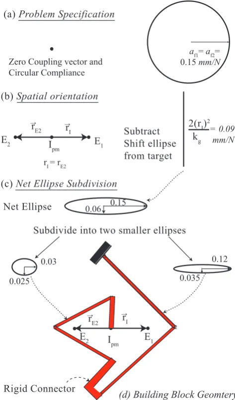
Consider an example where equal biaxial (X and Y) stiff -ness is required at a point without any coupling translational and rotational terms. Such a specification is required for a vision-based force sensor (Cappelleri et al., 2010), where ex-ternal applied force can be evaluated by measuring the de-formation of a point. Such a problem specification requires a circular compliance ellipse with zero coupling vector mag-nitude shown in Fig. 7a. Comparing from the database of compliant dyads no design matches these specifications (Kr-ishnan et al., 2011). Figures 7b–c and 8 illustrate achieving these specifications using series and parallel combination of dyads. In series combination, the coupling vectors of indi-vidual building blocks add. Thus the zero coupling vector specification can be achieved by aligning equal and opposite building block specifications. Since the degenerate shift el-lipse depends on the coupling vector orientations alone, its magnitude can be evaluated and subtracted from the required ellipse to obtain a net ellipse (Fig. 7b). Two dyads are then chosen from the building block library to meet the ellipse specifications. The next step involves assembly of dyads be-tween themselves, and bebe-tween one of the dyads and the in-put using rigid connecters as they donot change the compli-ance characteristics at the CoE of a building block. Thus all the steps illustrated in Fig. 1 are accomplished with geomet-rically intutive quantities.
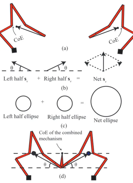
One of the limitations of series combination is that the CoE always lies within the footprint of the mechanism (for proof of this, please refer Krishnan et al., 2011). This does not provide an easy access of the input for interacting with the objects in the vision based force sensor application. To overcome this, parallel combination of building blocks are recommended. During parallel combination, the stiffness el-lipses and striffness coupling vectors of the building blocks add. Two sub-mechanisms whose stiffness ellipses are cir-cular and whose stiffness coupling vectors are aligned equal and opposite to each other are connected together as shown in Fig. 8. A practical realization of this involves parallel com-bination of symmetric halves with some accommodation for a rigid probe as shown in Fig. 8d. The resulting input has equal biaxial compliance and decoupled translational and ro-tational compliance.
Thus, it is shown how compliance representation in the form of eigen-twist and eigen-wrench parameters enables a systematic and insightful building block method to synthe-size single-port compliant mechanisms.
4 Multi-port compliance: load flow analogy
In the previous section we dealt with compliance where de-formation was directly actuated by an applied force at the required point. There are a number of transmission prob-lems such as grasping objects and amplifying, where force applied is spatially separated from the required output de-formation. The challenge for the building block method is
E2 I E1
pm rE2
→
rI
→
Subtract Shift ellipse from target
2(rI)2 kg
1
2
3
1
2 3
E2 I E1
pm rI
→
rE2
→
Net Ellipse
Subdivide into two smaller ellipses (a) Problem Specification
(b) Spatial orientation
(c) Net Ellipse Subdivision
Rigid Connector Zero Coupling vector and Circular Compliance
af1= af2= 0.15 mm/N
= 0.09 mm/N
0.06 0.15
0.12 0.035 0.03
0.025
rI = rE2
(d) Building Block Geomtery
Figure 7. Guidelines with an example. (a) Problem Specification in terms of Compliance Ellipse and Coupling vector (b) Choose E1,
E2, Ipmand evaluate shift ellipse (c) Net ellipse evaluation and
sub-division into smaller building block ellipses (d) Design geometry of the two building blocks and their orientation.
formulating a representation for relative compliance between any two points in a continuum that can facilitate a building block method. In other words, it must enable representation of problem specification that can easily be decomposed into tractable subproblems. In this section, we present a load flow based analogy of relative compliance representation.
Between two points in a continuum, the relation between the applied forces and deformation is obtained from the ex-tended form of the compliance matrix as shown below.
" uin
uout
#
=
"
Cin Cin-out
CTin-out Cout
# " fin
fout
#
(1)
CoE
θ θ
CoE of the combined mechanism
θ θ
+ =
(d)
Left half sv Right half sv Net sv
+ =
Left half ellipse Right half ellipse Net ellipse
CoE
(a)
(b)
(c)
Figure 8.Parallel Combination (a) Two symmetric halves (b) Ad-dition of Stiffness Coupling Vectors (c) Addition of Stiffness el-lipses (d) Final mechanism with a rigid probe.
where uinand finare the displacements and applied load
re-spectively at the input, and uoutand foutare the displacements
and applied load respectively at the output. Load transfer be-tween the two ports is defined as an equivalent applied load at the output that produces the same output displacement as a unit input load. Load transfer can be thus defined as the output load that would cause the same output deformation as an applied input load as shown in Fig. 9. This is similar to the notion of transferred forces defined in Harasaki and Arora (2001). The relation between this transferred load and the applied load is given by the LT matrix given by Eq. (2).
˜ftr=C−out1C
T
in-outfin
TL=C−out1C
T
in-out (2)
where TL is the Load Transfer (LT) matrix that relates the
transferred load and the input load fin. The detailed
deriva-tion of the Eq. (2) is shown in Krishnan et al. (2010). Further-more, it must be noted that the transferred force in Eq. (2) is not the same as an applied output load in Eq. (1). The impli-cation of defining transferred load is that a two-port problem between the input and the output is converted into a single port problem where the transferred force acting at the output produces the required output displacement.
Input
fin uin fin= 0
(a) (b)
Figure 9.Deriving the Load Transfer matrix for Complaint Mecha-nisms (Krishnan et al., 2010). (a) Output displacement is evaluated for an applied input load (b) Output reaction load is evaluated by enforcing the output displacement from (a) with no input load. This reaction load is the transferred load.
While this characterization captures the relative compli-ance between two ports, its usefulness for a systematic syn-thesis is captured through an important property that enables modularity. Consider the two geometries and their deformed profiles in Fig. 10a and b. These geometries are composed of a beam that acts as an input constraint in series with a beam that connects the input and output. The output in Fig. 10a is constrained by a third beam which is absent in Fig. 10b. It is found that the transferred load evaluated at the output for the two different geometries is exactly equal, implying its inde-pendence on the output constraint. This property is true for all geometries consisting of a general input constraint in se-ries with a general transmitter element between the input and the output. The detailed proof of the property is presented in Krishnan et al. (2010). Thus, the fundamental building block for load transfer between two points is identified as a Load-Transmitter Constraint (LTC) set. The implication of this property in a mechanism composed of a number of LTC sets is that the transferred load in each LTC set can be inde-pendently evaluated of succeeding ones. This enables mod-ularity in analysis and design of two-port compliant mecha-nisms. One other observation is that the transferred load is independent of the deformation profile of the transmitter. For example, the transmitter in Fig. 10a is almost fixed-guided (like Fig. 2b), while the transmitter in Fig. 10b deforms as a rigid body.
G. Krishnan et al.: Building block method 21
1 2
3
1 2
3
4
α
α
α
Input Constraint
Transmitter
Output
Constraint
f
inf
inf
trf
tr~ ~
(c)
(b)
(a)
l
1l
2b
1b
2b
r=
b
2/
b
1l
2norm=
l
2/
l
1Figure 10. Comparison of two geometries containing (a) input constraint beam, transmitter beam and output constraint beam and, (b) input constraint beam and transmitter beam alone reveals that the transferred force at the output is independent of the output con-straint. (c) The output displacement depends on the orientation of the output constraint. In general any direction of the output dis-placement is permitted±90◦
with respect to the direction of trans-ferred force.
˜
ftr=
finy
sin(α) (3)
whereαis the inclination of the transmitter with respect to the constraint. Applying an input moment changes the direc-tion of the transferred force along with inducing transferred moment. The transferred force evaluated will then yield
˜
ftrx=cot(α) fin−
3(l2
2normcos(α)+b 3 r)mi
2l1(l2norm+b3r)l2normsin(α)
˜
ftry=fin−
3l2normmi
2l1(b3r+l2norm)
˜
mtr=−
b3 rmi
2(b3
r+l2norm)
(4)
where l2normis the ratio of the transmitter beam length to the
input constraint beam length, l1 is the length of input
con-straint beam length, br is the ratio of the transmitter beam
thickness (in-plane) to the input constraint beam thickness. The output transferred forces ( ˜fox and ˜foy) depends upon the input force and input moment. However, the output trans-ferred moment ( ˜mo) is dependent on the input moment alone and its direction is opposite to the input moment. Further-more, from the above equation, the magnitude of the trans-ferred moment is lower than the applied moment.
Though output constraints do not affect the transferred force, they determine the magnitude and direction of output displacement. Shown in Fig. 10c is a semicircular band±90◦
with respect to the transferred load. From the positive def-initeness of the stiffness or compliance matrix, the output displacement is constrained within this band. Its actual di-rection is dependent on the output constraint. For example
1 2 3
4 5 67
They do not intersect
1 2
∩
They intersect
1 3 2
1 3 2
1 2 3
4 5
(a) (b)
(c) (d)
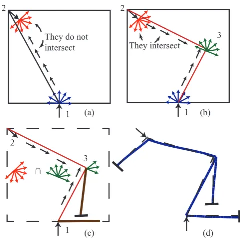
Figure 11. Steps involved in the load flow based conceptual syn-thesis of two-port compliant mechanisms. (a) Kinematic problem specification and the inability of a single load path to solve the prob-lem, (b) two load paths with the appropriate load flow directions that meet the kinematic specifications, (c) constraints that enforce the load flow directions must be oriented along a truncated band, and (d) final mechanism topology and the deformed configuration.
the output constraint beam in Fig. 10a constrains the output to move along the direction determined by the intersection of its degree of freedom with the semicircular band.
So far, we have formulated a representation for relative compliance between two distinct points, identified its unique properties that permit modular analysis and characterized a simple building block, namely a dyad. We will present a simple example of how this technique can be used for sys-tematic synthesis. Consider a problem specification shown in Fig. 11a where force applied at the input is at point “1” in the y-direction and the required displacement is at point “2” at an angle of −45◦. This is a nontrivial problem be-cause no direct connection between the input and output will yield the required kinematic specification. This is apparent from the figure as the direction of load flow in the transmit-ter does not intransmit-tersect with any of the semicircular band di-rections at the output. To enable intersection, the problem is decomposed into two load paths, and the direction of load flow in the transmitters is determined. The mechanism topol-ogy (i.e. the constraints) will be designed such that the pre-determined load flow directions are imposed. The constraints at input point “1” must enable y-direction displacement. A beam shown in Fig. 11c thus acts as the input constraint. The constraint at point “3” must be oriented such that load flow directions are preserved. This can be ensured if the degree of
1 2
3
4 5
6 7
8 9 10 11
12 13
14
15
16 17 18 19
20
21
22
23 24 25 26
27
28 29
1 2
(a) 3
4
1 2
(b) 3
4
1 2
(c) 3
4
(d)
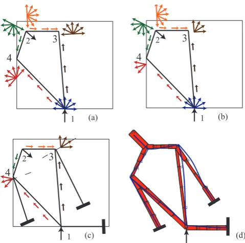
Figure 12.Steps involved in generating conceptual solutions hav-ing multiple load paths. (a) Kinematic problem specification and planning two parallel load paths between input and output, (b) trun-cated bands at each node, (c) constraints that enforce the load flow directions, and (d) final mechanism topology and the deformed con-figuration with widths of transmitters and constraints optimized so that the required deformation is achieved.
freedom direction of the constraint is along a truncated band obtained by the intersection of the bands at points “2” and “3” as shown in Fig. 11c. Furthermore the output constraint at point “2” is a beam that constraints it to move at an angle of−45◦. The deformed configuration is shown in Fig. 11d.
The example illustrates the generality of the methodology involving a single load path from input to the output. The same example can be used to demonstrate the use of multiple load paths between the input and the output. This is illus-trated in Fig. 12. The required direction of transferred load at point 1 can be obtained by a combination of load paths 1-3-2 and 1-4-2. The net load transferred due to each path add in proportion to the stiffness of the individual paths. For example, if stiffness of path 1-3-2 is greater than 1-4-2 then the former would dominate. If the stiffness of each load path is tuned so that they are equal, then the net load transferred is a vector combination of the individual paths. The constraints are designed in Fig. 12c such that they correspond to one of the truncated band directions. The widths of the constraints and transmitters are optimized such that the output in point 2 moves along a 45◦angle.
Thus, a number of conceptual solutions can be gener-ated by planning load paths and constraints using the above method. Comparison of each conceptual solution in terms of stress distribution, stiffness and mechanical efficiency is
re-5 Contributions and future research directions
This article shows how building block methods can be used to generate conceptual designs for compliant mechanisms. The ease with which kinematic specifications are met by systematic combination of simple deformable members, and the ability to quickly obtain alternate solutions highlights the usefulness of this method. Furthermore the lack of numeri-cal complexity and the emphasis on user insight makes this technique excellent for classroom education. It is the rep-resentation of compliance that enables this user insight into systematic synthesis. In this article, such a representation and synthesis methodology is reviewed for single port problems, where force displacement relationship is characterized at a single point of interest, and for multi-port problems where relative compliance between two or more ports are charac-terized.
5.1 Contributions
Representing compliance at a single point is accomplished by decoupling translational and rotational terms thus preserving dimensional consistency. Ability to represent translational compliance as an ellipse and the coupling between transla-tions and rotatransla-tions as vectors enables insightful quantifica-tion of the compliance characteristics. Series and parallel combination of any deformable member is explained as a ge-ometric combination of their individual ellipses and vectors. Thus solving for a given compliance characteristics, which was so far remotely accomplished through optimization is now possible through systematic, yet intuitive methods.
Synthesis of two-port mechanisms have always been con-sidered non-intuitive as the contributions of each member to-wards the overall mechanism behavior is hard to understand. This is the first attempt towards identifying the functions of each member as a transmitter and a constraint. Representing deformation behavior as load flow enables identifying and thus determining feasible load paths that meets a given kine-matic specification. Such a representation enables load path to act as a skeleton for the overall mechanism geometry. As seen in the examples, it is possible to synthesize single con-tinuous load path and multiple parallel load paths for any ap-plication with relative ease. This insight and ability to obtain alternate solutions with ease highlights the usefulness of this method.
G. Krishnan et al.: Building block method 23
5.2 Future research directions
The main challenge of compliant mechanism design is ob-taining distribution of stresses evenly within all its con-stituent members. While meeting kinematic specifications alone leads to multiple solutions, it is necessary to evalu-ate which of these solutions lead towards distributed com-pliance. Secondly, the effects of large deformations on com-pliance representations must be studied. In single-port de-sign this translates towards determining the change of the eigen-twist and eigen-wrench parameters with deformation. In two-ports the changes of load flow direction and magni-tude must be determined for large deformations. Thus, the future directions in building block methods is towards under-standing what constitutes distributed compliance, and formu-lating strategies in achieving them.
While planar examples were alone presented in this paper, the ideas proposed are as relevant to spatial mechanisms. The development of screw theory based methods (Hopkins and Culpepper, 2010a,b) in designing mechanisms with predetermined degrees of freedom and constraint can be considered as a spatial extension of the single port problem. However in mechanisms with relative deformation between two or more ports that are not in general connected by a rigid body, a combination of screw theory and load flow can be envisioned.
Edited by: J. Herder
Reviewed by: two anonymous referees
References
Ananthasuresh, G. K.: A new design paradigm in microelectrome-chanical systems and investigations on compliant mechanisms, Ph.D. thesis, Ann Arbor, MI, USA, 1994.
Awtar, S., Slocum, A. H., and Sevincer, E.: Characteristics of beam-based flexure modules, J. Mech. Design, 129, 625–639, 2007. Canfield, S. L., Chlarson, D. L., Shibakov, A., Richardson, J. D.,
and Saxena, A.: Multi-objective optimization of compliant mechanisms including failure theories, ASME Conference Pro-ceedings, 48094, 179–190, 2007.
Cappelleri, D.: Flexible automation of micro and meso-scale ma-nipulation tasks with applications to manufacturing and biotech-nology, Ph.D. thesis, Philadelphia, PA, USA, 2008.
Cappelleri, D. J., Krishnan, G., Kim, C., Kumar, V., and Kota, S.: Toward the design of a decoupled, two-dimensional, vision-based mu n force sensor, Journal of Mechanisms and Robotics, 2, p. 021010, 2010.
Ciblak, N. and Lipkin, H.: Design and analysis of remote center of compliance structures, Journal of Robotic Systems, 20, 415–427, 2003.
Erdman, A., Sandor, G., and Kota, S.: Mechanism Design: Analysis and Synthesis Volume I, Prentice Hall, Upper Saddle River, New Jersey, 2001.
Harasaki, H. and Arora, J. S.: New concepts of transferred and po-tential transferred forces in structures, Comput. Methods Appl. Eng., 191, 385–406, 2001.
Hopkins, J. B. and Culpepper, M. L.: Synthesis of multi-degree of freedom, parallel flexure system concepts via freedom and con-straint topology (fact) – part i: Principles, Precision Engineering, 34, 259–270, 2010a.
Hopkins, J. B. and Culpepper, M. L.: Synthesis of multi-degree of freedom, parallel flexure system concepts via freedom and con-straint topology (fact). part ii: Practice, Precision Engineering, 34, 271–278, 2010b.
Howell, L. L. (Ed.): Compliant Mechanisms, John-Wiley, 2001. Kim, C.: Functional characterization of a compliant building block
utilizing eigentwists and eigenwrenches, Proceedings of the ASME International Design Engineering Technical Conferences and Computers and Information in Engineering Conference, 5–7 August, Brooklyn, NY, USA, 2008.
Kim, C. J.: A conceptual approach to the computational synthesis of compliant mechanisms, Ph.D. thesis, Ann Arbor, MI, USA, 2005.
Kim, C. J., Moon, Y. M., and Kota, S.: A building block approach to the conceptual synthesis of compliant mechanisms utilizing compliance and stiffness ellipsoids, J. Mech. Design, 130, 1–11, 2008.
Kota, S. and Chiou, S.-J.: Conceptual design of mechanisms based on computational synthesis and simulation of kinematic build-ing blocks, Res. Eng. Des., 4, 75–87, doi:10.1007/BF01580146, 1992.
Krishnan, G., Kim, C., and Kota, S.: Load-transmitter constraint sets: Part i – an effective tool to visualize load flow in compliant mechanisms and structures, 2010.
Krishnan, G., Kim, C., and Kota, S.: An intrinsic geometric frame-work for the building block synthesis of single point compliant mechanisms, Journal of Mechanisms and Robotics, 3, p. 011001, 2011.
Lipkin, H. and Patterson, T.: Geometrical properties of mod-eled robot elasticity: Part i-decomposition, ASME Design Tech. Conf. and Computers in Engineering Conf., 45, 179–185, 1992. Saxena, A. and Ananthasuresh, G. K.: A computational approach to the number of synthesis of linkages, J. Mech. Design, 125, 110–118, 2003.
Sclater, N. and Chironis, N. P.: Mechanisms and Mechanical De-vices Sourcebook, McGraw-Hill, New York, 2007.
Yin, L. and Ananthasuresh, G. K.: Design of distributed compli-ant mechanisms, Mechanics based design of structures and ma-chines, 2003.