Themed Section: Science and Technology
Harmonic Analysis and Switching Angle Calculation by Equal
Phase Method for Cascade H-Bridge five level Inverters
Chetna Chhangani1 , Dr. M.K Bhaskar2 , Surbhi bhandari3 *1 EE, MBM, Jodhpur, Rajasthan, India
2 EE, MBM, Jodhpur, Rajasthan, India
3 ECE, JIET, Jodhpur, Rajasthan, India
ABSTRACT
Multilevel inverters have become very popular in the last few years, due to their advantages over the conventional two level inverters, in producing sinusoidal waveform with low distortion, high quality and high efficiency. Many topologies of multilevel inverter have been proposed during the last three decades, aiming to construct a sinusoidal waveform. It is hard to connect a single power semiconductor switch directly to medium voltage grids (2.3, 3.3, 4.16, or 6.9 kV). For these reasons, a new family of multilevel inverters has emerged as the solution for working with higher voltage levels. Multilevel inverters have received more attention in industrial application, such as motor drives, static VAR compensators and renewable energy systems, etc. Primarily multilevel inverters are known to have output voltages with more than two levels. As a result, the inverter output voltages have reduced harmonic distortions and high quality of waveforms. Additionally, the devices are confined to fraction of dc-link voltage. These characteristics make multilevel inverter to adopt for high-power and high-voltage applications. Although different multilevel inverter exists, Cascade Multilevel Inverter (CMI) is one of the productive topology from multilevel family. In reality, on comparing with other multilevel based topologies, CMI feature a high modularity degree because each inverter can be seen as a module with similar circuit topology, control structure, and modulation. Therefore, in the case of a fault in one of these modules, it is possible to replace it quickly and easily. Moreover, with an appropriated control strategy, it is possible to bypass the faulty module without stopping the load, bringing an almost continuous overall availability. All this features make CMI an outstanding power converter.
Keywords : Multilevel Inverters, Cascaded, Switching Time, Equal Phase Method
I.
INTRODUCTIONMULTISOURCE CASCADED H-BRIDGE
MULTILEVEL INVERTER
The serially connected H-bridge with separate DC source is called as cascaded H-bridge multilevel inverter. In this type of configuration voltage on each DC source is same value. The multi-level inverter has been introduced since 1975 as alternative in high power and medium voltage situations. The Multi-level inverter is like an inverter and it is used for industrial
applications as alternative in high power and medium voltage situations.
A. Concept of Multilevel Inverters
semiconductors have to withstand only reduced voltages.
Herein, we should remember one important thing i.e. as the number of steps increases in the output waveforms; harmonic content comes down [3]. Thus power quality of such waveforms will increase drastically. However, in order to generate step kind of waveforms in output side, different Multilevel based archetypes are successfully built and verified. But general principle of multilevel inverters is the synthesis of the ac voltage from several different voltage levels on the dc bus. As the number of voltage levels on the input dc side increases, the output voltage adds more steps [4-6], which approach the sinusoidal wave.
The need of multilevel converter is to give a high output power from medium voltage source. Sources like batteries, super capacitors, solar panel are medium voltage sources. The multi-level inverter consists of several switches. In the multi-level inverter the arrangement switches’ angles are very important.
Multilevel inverters are three types.
Diode clamped multilevel inverter
Flying capacitors multilevel inverter
Cascaded H- bridge multilevel inverter
B. Cascaded H-Bridge Multilevel Inverter:
The cascaded H-bride multi-level inverter is to use capacitors and switches and requires less number of components in each level. This topology consists of series of power conversion cells and power can be easily scaled. The combination of capacitors and switches pair is called an H-bridge and gives the separate input DC voltage for each H-bridge. It consists of H-bridge cells and each cell can provide the three different voltages like zero, positive DC and negative DC voltages. One of the advantages of this type of multi-level inverter is that it needs less number of components compared with diode clamped
and flying capacitor inverters. The price and weight of the inverter are less than those of the two inverters. Soft-switching is possible by the some of the new switching methods.
Multilevel cascade inverters are used to eliminate the bulky transformer required in case of conventional multi-phase inverters, clamping diodes required in case of diode clamped inverters and flying capacitors required in case of flying capacitor inverters. But these require large number of isolated voltages to supply the each cell.
Example: 5- bridge multi-level inverter, 9- H-bridge clamped multi-level inverter. This inverter is also same like that diode clamped multi inverter.
Fig 1 H Bridge multi-level inverter
seen as a module with similar circuit topology, control structure, and modulation [8]. Therefore, in the case of a fault in one of these modules, it is possible to replace it quickly and easily. Moreover, with an appropriated control strategy, it is possible to bypass the faulty module without stopping the load, bringing an almost continuous overall availability [9].
CHB-MLIs formed by the series connection of two or more single-phase H-bridge inverters, hence the name [11]. Each H-bridge corresponds to two voltage source phase legs, where the line–line voltage is the inverter output voltage. Therefore, a single H-bridge converter is able to generate three different voltage levels. Each leg has only two possible switching states, to avoid dc-link capacitor short-circuit. Since there are two legs, four different switching states are possible, although two of them have redundant output voltage. So when two or more H- bridges are connected in series, their output voltages can be combined to form different output levels, increasing the total inverter output voltage and also its rated power.
II.
SWITCHING ANGLESwitching angle is the moment of the voltage level change at the output. For an m-level waveform as shown in fig.4 there are 2(m-1) switching angles are needed. We call them as α1, α2, α3,………. αm-2, α
m-1.Since the sine wave is a symmetrical waveform, as
shown in fig., the negative half cycle is centrally symmetrical to its positive half cycle; and the waveform of the second quarter period is mirror symmetrical to the waveform of its first quarter period. So we call the switching angles in the first quadrant period i.e., 00-900 as main switching angles.
A. Main Switching Angles
In the first quarter of the sine wave (i.e., 00 to 900): α1, α2, α3, α (m-1)/2 (1)
The switching angles in the second quarter of the sine wave (i.e., 900 to 1800) are:
α (m+1)/2= Π-α(m-1)/2, Π- α(m-2)/2 ,… Π-α1 (2)
The switching angles in third quadrant of the sine wave (i.e., 1800 to 2700) are
αm=Π+α1, …….., Π+α(m-1)/2 (3)
The switching angles in the fourth quadrant (i.e., 2700 to 3600) are:
α(3m-1)/2 =2Π-α(m-1)/2,……….2Π-α1 (4)
From the above analysis it was concluded that we need to determine only the main switching angles (i.e., from 00 to 900), the other switching angles (i.e., from 900 to 3600) can be obtained from the main switching angles in the first quadrant.
B. Methods to calculate switching angle for cascade H-bridge inverters
There are following four methods:-
1. Equal Phase (EP) Method. 2. Half Equal Phase (HEP) Method. 3. Half Height (HH) Method. 4. Feed Forward (FF) Method.
We are discussing only Equal phase method in this paper.
1) Equal Phase (EP) Method: In the equal phase method the switching angles are distributed averagely in the range 0-Π.The main switching angles are obtained by the formula given below:
αi = i * 1800/𝑚 where i=1, 2 ,… (m-1) /2 (5)
III.
SINGLE PHASE FIVE LEVEL INVERTER BY EQUAL PHASE METHODindividual cell outputs. The output voltage is given by V=V1 +V2 Where the output voltage of the first cell is labeled V1 and the output voltage of the second cell is denoted by V2. There are five level of output voltage i.e 2V, V, 0, -V, -2V.The main advantages of cascaded H-bridge inverter is that it requires least number of components, modularized circuit and soft switching can be employed. But the main disadvantage is that when the voltage level increases, the number of switches increases and also the sources, this in effect increases the cost and weight.
The cascaded H-bridge multilevel inverters have been applied where high power and power quality are essential, for example, static synchronous compensators, active filter and reactive power compensation applications, photo voltaic power conversion, uninterruptible power supplies, and magnetic resonance imaging. Furthermore, one of the growing applications for multilevel motor drive is electric and hybrid power trains.
Figure: 2 Single phase five level multilevel inverter
Figure: 3 output voltage
The number of H bridges (N) = (m-1)/2
Here m= 5 so N =2 H bridges
The main switching angles are obtained by the formula given below:
αi = i * 1800/𝑚 where i=1, 2 ,……(m-1) /2 Where,
m= level of output voltage, here m= 5 α = switching angle
Total switching angles = 2(m-1), here total switching angles = 8 Now main switching angles are α1 = 1*1800/5 = 360
α2 = 2*1800/5 = 720
Rests of the switching angles are α3 =1800-720 = 1080
α4 =1800-360 = 1440 α5= 1800+360 = 2160 α6 =1800+720 = 2520 α7= 3600-720 = 2880 α8= 3600-360 = 3240
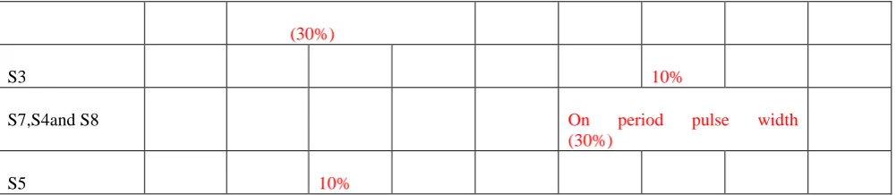
A. Switching Time Table for five level Single Phase Inverter
Pulse number 0 V 2V V 0 -V -2V -V 0
Angle 360 720 1080 1440 2160 2520 2880 3240 3600
Time(sec) 0.002 0.004 0.006 0.008 0.012 0.014 0.016 0.018 0.02
(30%)
S3 10%
S7,S4and S8 On period pulse width
(30%)
S5 10%
Table 1 Switching Time table for five level inverter
B. Simulations and Result Discussion
In this chapter simulations are carried out with and without filter for different cascaded 3, 5 and 7 level inverters and FFT analysis is done in MATLAB/SIMULINK to obtain
THD. For all simulation results on Y-axis voltage in volts is taken and on X-axis time is taken in seconds. Dc voltage is taken as 100 volts for every multi-level inverter.
LCL filter is used to reduce the harmonics.
C. Five level inverter with and without filter with staircase technique
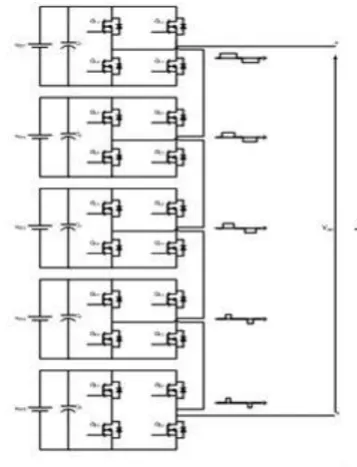
Figures shows block diagram structure in MATLAB/SIMULINK for 5 level cascaded MLI. It shows single phase cascaded H-Bridge multilevel inverter consisting of two H-Bridges with 8 MOSFET switches, two DC sources and, R-L load. In this eight MOSFET switches are (switch1, switch2.switch3, switch4, switch5, switch6, switch7, and switch8) are used. Two H-Bridges are connected in series to generate five level output voltage.
The output voltage of H-Bridge inverter 1 is V1 and H-Bridge 2 is V2 & total output voltage of 5 level inverter is V, is V=V1+V2.
1) Working Operation of Five Level Inverter:
The working operation of cascaded H bridge five levels multilevel is explained below:
Mode1:- In this mode of operation single phase five level cascaded H-Bridge multilevel inverter switch1; switch3,switch5 and switch7 are turned on without connecting source to the load. The output voltage across the load obtained is zero.
Mode2:- In this mode of operation single phase five level cascaded H-Bridge multilevel inverter switch1, switch3, switch5 and switch8 are turned on. The output voltage across the load obtained is +Vdc2. Mode3:-In this mode of operation single phase five level cascaded H-Bridge multilevel inverter switch1, switch4, switch5 and switch8 are turned on. The output voltage across the load obtained is Vdc1+Vdc2. Mode4:-In this mode of operation single phase five level H-Bridge cascaded multilevel inverter switch2, switch4, switch6 and switch7 are turned on. The output voltage across the load obtained is -Vdc2. Mode5:-In this mode of operation single phase five level H-Bridge cascaded multilevel inverter switch2, switch4, switch6 and switch8 are turned on. The output voltage across the load obtained is zero.
Mode6:- In this mode of operation single phase five level H-Bridge cascaded multilevel inverter switch3, switch2, switch7 and switch6 are turned on. The output voltage across the load obtained is –Vdc1-Vdc2.
Figure 4. Simulink model of 5 level inverter without filter
Figure 5. Scope output of 5 level inverter without filter
Figure 6. FFT analysis of 5 level inverter without filter
3) Simulink model and output of five level inverter with filter
Figure 7. Simulink model of 5 level inverter with filter
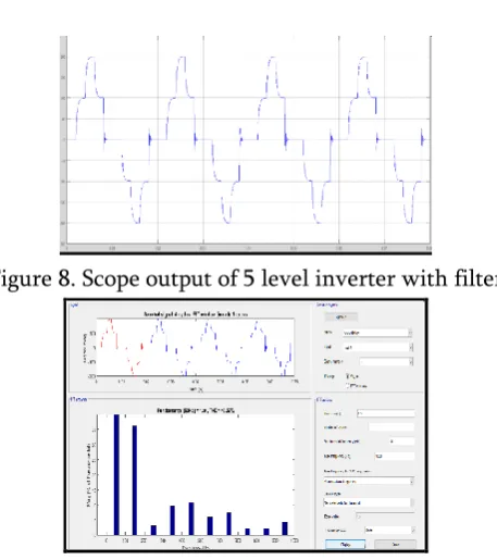
Figure 8. Scope output of 5 level inverter with filter
Figure 9. FFT analysis of 5 level inverter with filter
IV.
RESULT AND CONCLUSIONThe following table shows the effect on total harmonic distortion calculation of 5 level multilevel inverters with and without filter. This shows that by using filter distortion is reduced to lower level. This distortion can be further reduced by increasing the number of levels in a multilevel inverter, for eg. A 7 level inverter can be used.
Total harmonic distortion(THD) calculation of Five level multilevel inverters
(%)
41.04 40.57
Table 2. total harmonic distortion calculation with and without filter
V.
REFERENCES
[1]. IEEE Recommended Practices and
Requirements for Harmonics Control in Electric Power Systems, IEEE Std. 519, 1992.
[2]. A. Moreno-Munoz, Power Quality: Mitigation Technologies in a Distributed Environment. London, U.K.: Springer-Verlag, 2007.
[3]. N. G. Hingorani, “Introducing Custom Power,” IEEE Spectrum, Vol.32, n. 6, pp. 41-48, June 1995.
[4]. Ghosh and G. Ledwich, Power quality enhancement using custom power devices, London, Kluwer Academic Publishers, 2002. [5]. A Pandey, B Singh, B N Singh, A Chandra, K
Al-Haddad, D P Kothari, “A Review of Multilevel Power Converters”, IE (I) Journal.EL, vol. 86, pp.220231, March, 2006.
[6]. K.A Corzine, and Y.L Familiant, “A New Cascaded Multi-level H-Bridge Drive,” IEEE Trans. Power. Electron., vol.17, no.1, pp.125-131. Jan 2002.
[7]. Nasrudin Abd. Rahim, Mohamad Fathi Mohamad Elias, Wooi Ping Hew, IEEE transaction. Industry Electronics, “Design of filter to reduce harmonic distortion in industrial power system”, Vol. 60, No: 8, 2943-2956, August 2013.
[8]. M Malinowski, K. Gopakumar, J. Rodriguez, and M. A. Pérez, ?A Survey on cascaded multilevel inverters,? IEEE Trans. Ind. Electron., vol. 57, no. 7, pp. 2197-2206, July 2010.
[9]. Mohammad Ahmad and B.H. Khan, Senior Member, IEEE “New Approaches for harmonic reduction in solar inverters”.
[10]. J. Rodriguez. J.-S. Lai, and F.Z. Peng, “Multilevel inverters: A survey of topologies, controls and applications,” IEEE Trans. Ind. Electron., vol. 49, No. 4,pp. 724-738, Aug.
[11]. MariuszMalinowaski, Senior Member, IEEE, K.Gopakumar, Senior Member, IEEE, Jose Rodriguez, Senior Member, IEEE, and Marcelo A.Perez, Member IEEE “A Survey on Cascaded Multilevel Inverters”.
[12]. Gobinath.K1, Mahendran.S2, Gnanambal.I3 “New cascaded H-bridge multilevel inverter with improved efficiency.” International journal of advanced research in Electrical, Electronics and Instrumentation Engineering Vol.2, issue 4, April 2013.