MPPT Methods For PV String under Partially
Shaded Conditions Along with Particle Swarm
Optimization
K. Cheman Manikanta Dr. N. Bhupesh Kumar
PG Student Associate Professor
Department of Electrical & Electronic Engineering Department of Electrical & Electronic Engineering Sir C.R.R College of Engineering, Eluru Sir C.R.R College of Engineering, Eluru
Abstract
Many techniques are improvised with the help of maximum power point tracking but now we are examining the combination of global maximum power point tracking (GMPPT) with search- skip-judge method (SSJ) and rapid method (R) by forming a (SSJ-GMPPT) and (R-(SSJ-GMPPT) Which helps to track maximum power from PV string. And Particle Swarm Optimization algorithm (PSO) is used to reduce the tracking time. The mentioned methods are reduces the searching voltage range on current and voltage (I-V) and power and voltage (P-V) characteristics of PV string under partially shaded conditions (PSC).
Keywords: Maximum power point tracking (MPPT), partially shaded conditions (PSC), global maximum power point (GMPPT), particle swarm optimization (PSO)
________________________________________________________________________________________________________
I. INTRODUCTION
In present climatic conditions conventional energies are polluting the environment and fossil fuel is only generating the huge electricity, on the other hand renewable energies are improving day by day but we are not utilizing it in properly. From solar energy we can generate electricity by conversion of solar energy into electricity. Solar panel is the fundamental energy conversion component of photovoltaic (PV) system. The conversion efficiency depends on insolation levels, temperature and load conditions. The current – voltage and power – voltage relations of the PV array possess non-linear characteristics that are affected by irradiance intensity and temperature. So, to avoid these problems we have maximum power point (MPP) on PV array characteristics.
The object of MPPT is to ensure that, in varying environmental condition the system is always generating energy from PV panel. In MPPT many techniques are proposed like perturb and observe (P&O), Incremental conductance (IC), Global maximum power point (GMPPT). From the global maximum power point (GMPPT) we are used search- skip – judge global maximum power point (SSJ–GMPPT) and rapid global maximum power point (R–GMPPT) are more helpful in tracking the solar energy from PV string. While SSJ-GMPPT method can track the real maximum power point (MPP) under any shading conditions and achieve high accuracy and fast tracking speed and R-GMPPT method elaborates the tracking speed. Since 130 years the development of the first functional PV cell.
Electrical characteristics of a silicon PV cell are non-linear and have only one point at which the maximum power can be obtained, the maximum power point (MPP). Voltage and power at MPP of a single cell are relatively low. Due to low voltage and power ratings, a certain amount of PV cells are typically connected in series to form PV modules. PV module can further be connected in series and parallel to increase the voltage and power levels of the whole PV power generator. The effects of partial shading conditions on PV power generator has been noticed to be a major cause of power losses and lower-than-expected system efficiencies the effects of partial shading has been extensively investigated.
II. MAXIMUM POWER POINT TRACKING
There has been a great amount of research and development in the field of MPPT techniques. The operations of different MPPT techniques differ for example in convergence speed, range of effectiveness, complexity, required amount of sensors for measurement and implementation hardware. Direct methods ensure that the operating point is really at least at some of the MPPs. A conventional and popular direct method is the P&O algorithm. The basic idea is to perturb the operating point of the PV and observe the change in power. If power increases, the operating point is varied in the same direction also in the next step. If power decreases, the direction of the perturbation is changed. The algorithm does not recognize when it is at the MPP but keeps on oscillating around the MPP.
direct connection that results in operation at a sub-optimal point. The maximum power MP hyperbola intersects the I-V curve at a particular insolation level, at the MP point M1 and the actual load curve intersects the source curve at point I and the hyperbola at Imax where it is supposed to be utilizing the entire available power. Tracking algorithms thus have the task of virtually varying the slope of the load line to intersect the I-V curve at M1. The ideal load curve that intersects all the PV curves at maximum power points (M1, M2, etc.) is also shown in figure for illustration.
Fig. 1: Typical current and power versus voltage curves of a solar module.
III. PARTIALLY SHADED CONDITION
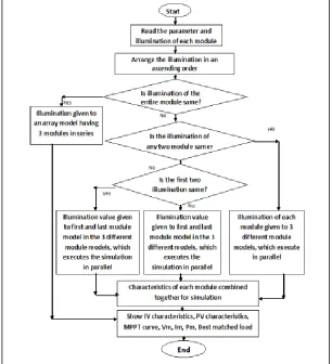
IV. GLOBAL MAXIMUM POWER POINT
Initially the global tracking process is performed and the voltage magnitude corresponding to each maximum power point is identified. There will be global maximum power point among the local maximum power point. On the global maximum power point tracking mentioned a flowchart as shown in figure 3 basically the GMPP has PV array. In this it has power converter control method so that the power an adjustable constant power loads.
Fig. 3: Flow chart of Global Maximum Power Point Tracking
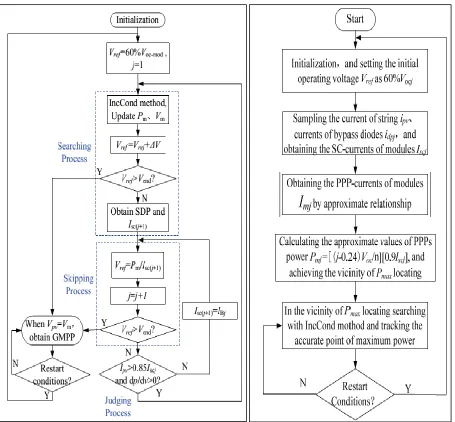
V. SEARCH SKIP JUDGE GLOBAL MPPT AND RAPID GLOBAL MPPT
Fig. 4: Complete algorithm flowchart of SSJ-GMPPT and Complete algorithm flowchart of R-GMPPT
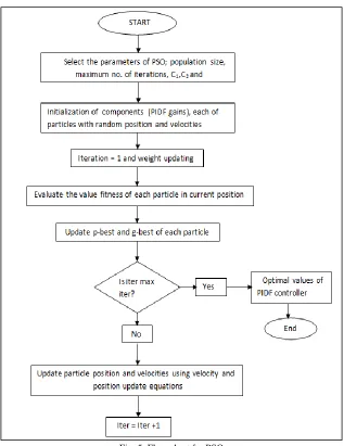
VI. PARTICLE SWARM OPTIMIZATION (PSO)
Fig. 5: Flow chart for PSO
The experimental setup and system block diagram are mentioned below for this system. Which is implemented in MATLAB Simulink for that simulation module adds particle swarm optimization (PSO) coding to reduce the tracking time and accuracy of the system.
Fig. 6: Experimental setup and system block diagram
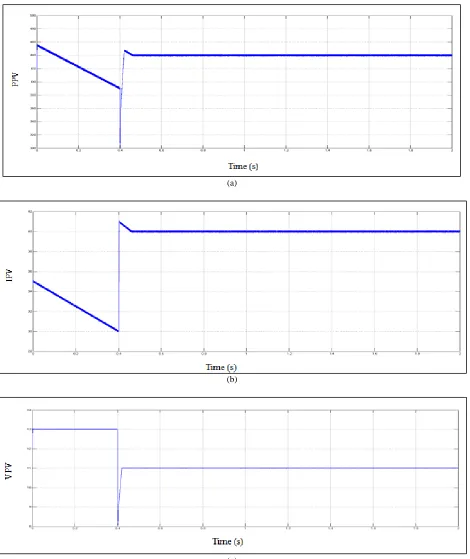
VII.SIMULATION RESULTS
(a)
(b)
(c)
Fig. 7: (a), (b) and (c) Simulation results for PSO GMPPT pattern
VIII. CONCLUSION
REFERENCES
[1] M. Boztepe, F. Guinjoan, G. Velasco-Quesada, S. Silvestre, A. Chouder, and E. Karatepe, “Global MPPT scheme for Photovoltaic string inverters based on restricted voltage window search algorithm,” IEEE Trans. Ind. Electron., vol. 61, no. 7, pp. 3302-3312, Jul. 2014.
[2] E. Koutroulis and F. Blaabjerg, “A new techniques for tracking the global maximum power point of PV arrays operating under partial-shading conditions,” IEEE J. Photovolt., vol. 2, no. 2, Apr. 2012.
[3] P. Sharma and V. Argarwal, “Exact maximum power point tracking of grid-connected partially shaded PV source using current compensation concept, ” IEEE Trans. Power Electro., vol. 29, no. 9, pp. 4684-4692, Sep. 2014.
[4] M.Z.S. El-Dein, M. Kazerani, and M.M.A. Salama, “Optimal photovoltaic array reconfiguration to reduce partial shading losses,” IEEE Trans. Sustain. Energy, vol. 4, no. 1, pp. 145-153, Jan. 2013.
[5] S. R. Shubhajit and H. Saha, “Maximum power point tracking of partially shaded solar photovoltaic arrays,” Solar Energy Mater. Solar Cells, vol. 94, no. 9, pp. 1441-1447, Sep. 2010.
[6] Y. Liu, S. Huang, and W. Liang, “A particle swarm optimization-based maximum power point tracking algorithm for PV systems operating under partially shaded conditions,” IEEE Trans. Energy Convers., vol. 27, no. 4, pp. 1027-1035, Dce. 2012.
[7] K. Ishaque, Z. Salam, M. Amjad, and S. Mekhilef, “An improved particle swarm optimization (PSO)–based MPPT for PV with reduced steady-state oscillation,” IEEE Trans. Power Electron., vol. 27, no. 8, pp. 3627-3638, Aug. 2012.
[8] B. N. Alajmi, K. H. Ahmed, S. J. Finney, and B. W. Williams, “A maximum power point tracking technique for partially shaded photovoltaic systems in microgrids,” IEEE Trans. Ind. Electron., vol. 60, no.4, pp. 1596-1606, Apr. 2013.
[9] N. Bhupesh Kumar, Sr. Assistant Professor, Department of EEE, Sir C R Reddy College of Engineering, Eluru “Fast tracking of the maximum power point of pv arraysusing fuzzy logic controller” IJERIA2012-13 ISSN: 2248-9278/Sep-Oct 13/Vol-2/Issue-1/Pg.1439-1444.
[10] N. Bhupesh Kumar, Sr. Assistant Professor, Department of EEE, Sir C R Reddy College of Engineering, Eluru ”Advanced Fuzzy Logic Controller for Tracking the Maximum Power Point of PV Arrays” (IJERT) ISSN: 2278-0181 Vol. 2 Issue 11, November – 2013.