~ 107 ~ WWJMRD 2019; 5(10): 107-115
www.wwjmrd.com International Journal Peer Reviewed Journal Refereed Journal Indexed Journal
Impact Factor MJIF: 4.25 E-ISSN: 2454-6615
Thi Minh Hao Dong
Ho Chi Minh city University of Transport, Ho Chi Minh city, Vietnam
Thanh Hai Truong
Ho Chi Minh city University of Transport, Ho Chi Minh city, Vietnam
Correspondence: Thi Minh Hao Dong
Ho Chi Minh city University of Transport, Ho Chi Minh city, Vietnam
The solution for efficient operation of MAN B&W
marine engine series
Thi Minh Hao Dong,
Thanh Hai Truong
Abstract
The main diesel engine of a ship is the heart of the ship, it determines the speed and the ability to effectively exploit the ship. Therefore, the exploitation of the engine safely, reliably and effectively is extremely important. Parts of marine diesel engines are made of different materials. Each type of material can only work with a certain temperature limit, so to ensure the safety of the engine's components, while the diesel engine must be cooled. According to the coolant, the diesel engine has two types: air-cooled diesel engine and water-cooled diesel engine. In some cases, it is difficult to arrange the installation of a water-cooled system, such as a diesel engine on land, a diesel engine used as an incident generator on board (the engine is installed on the upper floor). High above sea level). In these cases, people often equipped with small wind-cooled Diesel engines. For air-cooled engines, cylinder-shaped engines, which produce lubricant, have a wing-shaped structure, cooled by a blower installed on the front of the machine and driven by the engine. For large-capacity diesel engines, most are water-cooled. Although compared with air-cooled, water-cooled is more likely to cause thermal stress, corrosive details, but the cooling effect is higher. There are two methods of water cooling: direct cooling and indirect cooling. The cooling system directly takes sea water from outside the ship to cool the engine, after cooling is discharged directly into the sea. The cooling system is characterized by: Simple system, no need to equip fresh water welding, no need to pump cooling fresh water. This study investigated and identified the structural and operating characteristics of Hitachi 6S46 ME-B8.5 engines. From that point on, the influence on the process of the motor operating at low load when sailing.
Keywords: Efficient operation solutions, low load operation, MAN B&W S46ME-B8.5, exhaust valve, high-pressure pump
1. Introduction
The mode operates at low load when the sea voyage of the engine driving the propeller is used quite recently in various reasons. With the characteristic of electric-electronic fuel injection engine, but still using camshaft to control exhaust valve, in addition because it was newly put into use shortly, during operation at low load, engine 6S46ME -B8.5 in particular and ME-B / C line, in general, have generated some problems that significantly affect the operation of the ship. At the same time, the effects of the continuous low-load operation on the associated equipment and the details on the engine from which the measures and adjustments were determined. In particular, the article has deeply explored, analyzed and determined the causes of incidents on discharge cylinders on Hitachi 6S46 ME-B8.5 engines during operation at low load but not yet specified by the manufacturer to get the exact cause, thereby giving recommendations and measures in the process of harnessing the engine (next to the manufacturer's instructions). The paper analyzed and investigated the cause of the plunger problem of high-pressure pumps based on the design characteristics and operation mode of the engine, thereby giving necessary recommendations.
MAN B&W S46ME-B 8.5 engines manufactured by Hitachi, copyright of MAN B&W, designed capacity of 6260 kW, equipped on 34000 DW ships. Wisdom Marine Line is one of the owners using this type of engine on its wooden fleet. The service lines of these vessels are usually from North America or Australia, Newzeland to Japan, Korea or China[1]. The ME-B generation engine was first put into production in 2007, many years after the
~ 108 ~ introduction of the ME-C engine line aimed at the market, medium-sized propeller hybrid engines, cylinder diameter from 300 - 600 mm[2]. This is a potential market that, at present, when the demand for IMO air pollution is getting tighter, other companies have not met or did not develop in this direction[3].
Introduced in mid-2006 and put into production since 2007 with the first generation engines are S35ME-B9, S40ME-B9, and S50MES40ME-B9, followed by engines S46ME-B8, S50ME-B8, S60ME-B8. This generation is extended with longer stroke engines, G40ME-B9, G45ME-B9, and G50 ME-B9, with a range of power from 3200 kW to 19040 kW[4]. ME-B engines meet the following requirements: Control electronic fuel injection; Energy saving; Periodic maintenance cycles are longer; Low propeller speed; Good maneuverability (at low revs); Low cost of replacement materials; Satisfy Tier II of NOx emissions[5]. Also, like ME-C, from ME-B can continue to grow on dual-fuel (liquid - natural gas) engine.
Hydraulic system: Unlike ME-C, which has both hydraulic
pump by electric motor and hybrid engine, ME-B engine has only 2 hydraulic engines due to the hybrid electric motor. These hybrid electric motors operate automatically or manually, if automatic, are controlled by the position of the command bell. When the command bell hand is set to "Finish with Engine," these electric motors stop, when the bell is in position S / by, a hydraulic pump will automatically run and maintain the pressure at 225 bar[6]. During acceleration, if the load of the motor increases by 25%, the second hydraulic pump runs and together with the first pump maintains the required hydraulic pressure from the ECS control system[7].
ME-B engine fuel system: High-pressure pump is not
hybridized by mechanical cam but is hybridized by a hydraulic piston. ELFI valves control this piston-operated hydraulic oil. Hydraulic oil pressure varies with load. The plunger of the high-pressure pump does not have mechanical springs to return to the original position[8]. The reverse movement of the plunger is done by the force created by the fuel pressure acting on the plunger's upper surface. The plunger of the high-pressure pump is not slanted groove — the plunger's journey changes when the number of fuel changes. High-pressure pumps on the ME-B generation do not have plunger position sensors. On the high-pressure pump body, there is a suction valve, which is not the same as the previous engine. The fuel pressure before entering the high-pressure pump requires relatively high maintenance (~ 10 bar). Hydraulic oil pressure is maintained stable thanks to nitrogen gas storage tank (~ 140 bar N2). However, this pressure is easily reduced due to leakage[9].
Control fuel supply process: Similar to ME-C, the electric
valve from control ELFI to close/open hydraulic oil line (Servo Oil) to the high-pressure pump. Hydraulic pressure is maintained by the general energy tank of the HCU cluster. The position feedback signal of the ELFI valve accurately determines the amount of oil supplied to the cylinder. Electromagnetic valve ELFI is controlled according to the ratio rules.
Exhaust valve control: The ME-B engine still uses the cam
to drive the hydraulic pump to open the same valves as the previous MC, MC-C engine lines. However, when the load of the engine is more significant than 55%, a hydraulic oil branch from the ELFI control valve will act on the piston
MEV to support exhaust valve control[10]. The nature of this support changes the aperture of the valve at the same time (while the starting angle and closing angle remain unchanged). At the closing stage, the MEV piston provides an additional amount of hydraulic oil to the valve control, making the closing delayed valves, corresponding to delaying the closing process, but does not change the time of closing altogether.
Direct propeller hybrid diesel engines (fixed steps), when designed, are capable of operating at an extensive power range but with the best efficiency and fuel consumption in the rated extraction mode. However, for economic reasons, many ship owners or ship operators choose to operate at low load when the cruise ship is sailing. Thus, exploiting the propeller hybrid diesel engine in low load mode when the cruise ship is a technically inactive state. That is not the goal of producing a specific engine. There is no clear definition of "low load value", but from some manufacturers, operating at 40% load or lower is considered to operate at low load. However, reality shows that most ships operate only in the mode of no less than 50% load. When the shipowner only requires low-load operation without giving a specific value, then the decision belongs to the chief engine. Continuous operation at low loads is not only applicable to propeller hybrid engines; it also applies to service vessels with dynamic positioning systems or hybrid 4-stroke engines.
Fuel economy is the first benefit that ship owners can achieve. Without time constraints, without other reasons, owners often choose to operate the ship at a lower speed, corresponding to the small load mode of the propeller hybrid. At that time, the value of fuel consumption/distance of the cruise ship is considered. Shipowners and operators always make the requirement to exploit the engine in the most economical mode in this situation.
Secondly, in order to optimize the efficiency of its fleet operation, ship operators choose a small exploitation mode for the propeller hybrid engine to save the cost of anchoring due to various reasons[11]. The source of goods is scarce, or there is not enough stock to collect, or there is no cargo yard. Many ships are coming in ahead of time, which may cause ship owners to ask for ships to slow down in order to limit the cost of ships' anchoring, optimizing the ability of ship-to-shore coordination and minimizing the delay. However, whatever the reason, the goal of maximizing profits is still the top priority of ship operators.
~ 109 ~ plunger during acceleration. Engine and on startup. In addition, the engine generation before operating, low load limit allows only 40% of the load, however, the electric control motor allows continuous operation up to 25% of the load[14]. Before the above fact, the engine manufacturer has not found the exact cause for processing and there are no specific and suitable guidelines for ship owners.
This paper focuses on studying the effects and proposing effective exploitation solutions for engine MAN B&W 6S46ME-B8.5 in small load mode when marine ships travel on the sea. Determine the advantages when operating the engine in low load mode (Slow Steaming / Low load operation). Study the adverse impacts on engines and related machinery. Develop a process to exploit S46ME-B8.5 engine in low load mode. Troubleshooting on S46ME-B8.5 engine during the low load operation.
2. The effects of operating the engine in low steam 2.1. Affect the engine’s working process
Long-term continuous operation (sea voyage) at low and shallow load values will cause serious risks not only to the engine but also to other equipment such as exhaust gas turbines, industrial boilers by carbon soiling on surfaces on the exhaust gas circulation when discharged into the environment.
When operating at low loads, the pressure in the cylinder decreases, leading to a decrease in temperature. Low cylinder temperature increases the ability to cause problems with the compression-burning process of the fuel, the time of starting the fire will be later, less burning forms soot and the components of the fire are not complete. Black, carbon deposits or residues of fuel cling to pipes and surfaces where they pass (exhaust valves, exhaust gas manifold), reduce engine power.
Low exhaust gas temperatures have the potential to increase corrosion caused by sulfuric acid on exhaust gas piping systems, especially on the industrial boiler side. In case the engine operates continuously when the sea voyage is at a load of 40% or less, the auxiliary fan will change the status of "running" / "stop" continuously due to the automatic control pressure relay, consequently can damage the hybrid motor or electric devices on the starter. For engines using high-pressure pumps that are transmitted by camshafts, the fuel injection pressure depends in part on the engine's rotation speed. In low-load mode, the injection pressure is reduced, which can cause many fuel injection particles to be significant without burning. At low speeds, with engines using new generation nozzles (slide type) still ensure excellent performance when operating continuously
at a load value reduced by 10-20%[15]. However, the engines using the previous generation nozzle are recommended that the lowest load limit is at 40% when the engine operates continuously for a long time. Exploiting at a lower load may cause these engines to experience unexpected failures or incidents. Also, from this reason, the manufacturer offers a way to change the nozzle to a new form on old engines to allow continuous operation at lower load values. However, obviously, this will cause many difficulties, from having to stop the engine to replace it to have two types of nozzles for different operating modes. For engines that seal at piston rod, the impact from the combustion chamber and the air cavity sweeps down the lubricants, which can be omitted if the sealing capacity of the piston seal is maintained. However, it does not exclude the possibility of leakage of sweeping components, including fuel, residual lubricating oil or soot components, carbon deposits[16] that affect the quality of engine lubricating oil.
2.2. Effects related devices
Auxiliary blower
When operating with loads as low as 25%, auxiliary blowers must operate continuously, with extended time, increasing the risk of damage[17]. Besides, if the exhaust pipe is clogged, the pressure in the sweeping air chamber will push the sweeping gas, dust, and debris from the wind cavity to the side of the bearing, thus making it possible to lose lubrication to the bearings.
Exhaust gas boiler
When the engine is operating in small load for a long time, the amount of carbon soot on the heat exchange surfaces of the exhaust gas boiler increases due to poor combustion in the cylinder. Besides, the low exhaust gas pressure makes the speed of exhaust gas flow through the boiler very low, not enough to blow the soot layer on the pipe surfaces[18]. These causes can cause damage to the boiler.
Carbon black if not controlled, can cause fire or in a worse situation, which can melt and deform the tube.
Depending on the structure of each type of boiler, make sure the by-pass line layout for the exhaust gas boiler, use when the engine is in small load mode.
The by-pass branch arrangement gas is discharged through the boiler when it is under load or even when there is no shortage of steam to do the heating task. The auxiliary boiler must operate continuously to ensure the maintenance of the necessary vapor pressure, thus increasing fuel consumption, especially for regional vessels such as East-North Asia and East-North America.
~ 110 ~ Exhaust valves
Operating small engines for a long time makes faster carbon formation on seat surfaces. Also, the risk of black carbon entering the gap between the guide pipe and a stem increases, the valve can be stuck in any position.
Also, the rotation of the valve is achieved by the speed of
the exhaust gas flow impacting on the blades mounted on the stem, because the low exhaust rate escapes so the valve rotates slowly or even does not rotate, limited the process of self-cleaning of contact surfaces of valves.
Fig. 2: Exhaust valve status when operating continuously at low load[20]
Scavenging space
The scavenging space sweeps faster due to lower scavenge air pressure, lower scavenge gas temperature, poor burning
fuel, causing more carbon deposits, excess lubrication of larger cylinder lubricants.
Fig. 3: Status of scavenging space
The one-way shield behind the turbocharger air conditioner enters the scavenging space. When the auxiliary fan runs/stops continuously, these shields repeatedly hit their seat to break, chipping out the outer edges. This phenomenon can be detected through sound, metal impact
noise inside the scavenging space, created by pressure pulses acting on these plates. If these shields are broken, it should be replaced as soon as possible because otherwise, it will reduce the efficiency of the auxiliary fan when the auxiliary fan runs, the amount of intake air decreases.
~ 111 ~
Injector
Low fuel pressure due to low engine speed (high-pressure pump hybridized by camshaft), low hydraulic oil pressure (ME engine), weak injector technical condition along with
other fire conditions (low pressure, low end-end temperature, lower clean air volume) leads to rapid fouling on the nozzles.
Fig. 5: Nozzle and impact on the seat of the exhaust valve [18]
Lubricate liner / piston-cylinder
The engine camshaft hybridizes the engine with the cylinder oil pump, the pump speed depends in proportion to the engine speed, regardless of the load. Therefore, when operating in a lower load mode, the reduction rate is not much, which can lead to excess cylinder oil. Excess cylinder oil will create residue, oil additives can damage the condition of the cylinder, especially when combined with the process of increasing the load for the engine. Cylinder liner is easily caught in the dark spot near the scanning door. This phenomenon is determined to be a combination of excess cylinder lubricating oil and steam in the scavenge air. Although, according to the manufacturer's
assessment, these dark spots are not harmful but will make many people misunderstand about the special status of liners.
The piston crown and the top part of the piston ring upwards stick deposits and soots faster when the engine operates at low load for a long time. This soot can break and insert out through the gaps of the piston rings when the engine is operating or in a stop state to wear the rings, reducing the sealing performance of the cylinder, reducing the pressure at the end of the compression stroke. Further, it can lead to blow molding due to the leak-down gas, and heavier can lead to fire scanveging space.
Fig. 6: Status of liner surfaces
3. The solution to operating the MAN B&W S46 ME-B8.5 engines in small load mode
3.1. Solution for problems on the high-pressure pump
According to reports from some ships, the problem occurs on the high-pressure pump of one or more cylinders, the plunger of the pump is unable to move, so there is no supply of fuel into the cylinder.
a.Statistics source
The incident occurred on MT. Paloris taker, equipped with the main machine 6G50ME-B9.3 T II, built at HHI-Vinashin shipyard in 2014 when the ship anchored in Singapore. Besides, there were reports of incidents on the ME-C line on the ship managed by Vinic Company when the ship was on a voyage.
b.Phenomena
When the main engine starts to leave the anchor area in Singapore, the engine cannot start. Predict why the fuel is not supplied to the engine for some reason.
c.Instant handling
- Check the suction valve of the high-pressure pump; all suction valves are in good condition, not stuck.
- Suspecting that the pump's plunger is stuck, check that 4 out of 6 high-pressure pumps (pumps No. 1,2 and 5,6) are stuck with the plunger. All jammed plungers are removed with the cover on the high-pressure pump, and it is difficult to remove the plunger from the upper cover of the pump due to jamming.
~ 112 ~
d.Causes
Through checking the surface of plunger and cylinder surface on high-pressure pump cap, no scratches, roughness, mechanical edges are detected. Signs of scale on
the plunger body on the lower and top part of the hydraulic piston show that the fuel leaks down, grips and traps. Leakage position can be from sealing gaskets or from the plunger work surface itself.
Fig. 7: Plunger status is stuck and new
Apart from being able to cause plunger jam, some other causes can lead to loss of fuel supply as above:
- The suction valve on the high-pressure pump body is jammed, fuel is not supplied into the pump.
- Fuel pressure is so low that it is not enough to push the plunger back to its dead, dead spot or cannot move the plunger.
e.The essence
On the ME-B / C engine, the stroke of the high-pressure pump is proportional to the engine load (the amount of fuel supplied to the cylinder), so the plunger does not always move to the top dead point (like the engine MC). If the engine operates for a long time in low load mode, the plunger does not work on the entire journey. If leakage occurs as a problem on the fuel, deposits on the surface will cause plunger stuck on the loading of the engine increases (journey of the plunger rise through deposits).
f.Corrective and preventive
- Maintain fuel pressure according to manufacturer's instructions (~ 10 bar)
- When operating at low load, the daily load should increase the load more than the prescribed time, increase the load slowly and up to 75-85% load.
- Maintenance and replacement of sealing seals according to the plan are shown in the instruction manual.
- Check fuel quality to ensure components are harmful to plunger's working surface.
- Fuel pressure monitoring if detecting any fluctuation, attention should be paid to leakage, especially when running at high load and when operating with LS MGO.
3.2. Solution for the exhaust valve
Incomplete statistics show that the incident occurred at least on 4 34000 DWT series ships of different ship owners, based in China and Japan. The engine is made in DMC (China), HITACHI (Japan) have in common is the same version of the engine used MAN B&W 6S ME-B8.5
a.Phenomena
When the main machine runs in small load in the cruise mode, in the time of increasing the load for the engine to the value of normal mining at least 1 hour of operation to wash the turbine. Blowing black boiler, at the loading stage increased up to 60-80%, suddenly the engine speed fluctuated strongly, load indicator surged, indicating the level of fuel supply increased even to 100%.
Distance A: The movement of exhaust valve (from the closed position to fully open)
Distance B (A = B): Regarding meaning B is similar to A but because the indicator bar rests on the high end of the winding cylinder.
Distance C: The distance from the position completely closed to the position where the indicator bar is limited due to the slot.
About a few seconds or later, a powerful impact is heard on the engine discharge side, after which the engine speed returns to normal, but the phenomenon can be repeated continuously, or the motor speed is ceaseless.
In typical load mode (65-80%) when the sea voyage does not occur.
b.Instant handling
When the speed of change is detected, immediately ask for the cockpit's opinion to reduce the engine speed. When permitted, reduce the speed to the value at which the speed is no longer fluctuating, the speed decreases in many cases, it is possible to move to the HALF speed. Maintain this speed for 5-10 minutes then increase the speed of the engine again, if the problem repeats, it must slow down and maintain at a lower speed for longer.
c.Explain the phenomenon
For some reason, a discharge valve does not close all on the closed journey, resulting in that cylinder does not burn, does not give birth. Only five cylinders are left, causing the engine speed to fluctuate strongly, the amount of fuel supplied to the cylinder increases to ensure maintaining the set speed.
~ 113 ~
d.Harm
Overload for the remaining cylinders; Power imbalance between cylinders; Imbalance in torque on the shaft; Risk of fire and explosion on exhaust manifolds and turbochargers. When there is no other adjustment, the fuel is still supplied to the cylinder which has trouble but does not burn, goes to the exhaust manifold, if this amount of fuel accumulates or the content is large enough, it can cause fire and explosion causing try more serious. Safety loss in the case of a ship or a moving area is restricted.
e.Causes
Until now, manufacturers have not identified the cause of
the phenomenon. The manufacturer makes some
assumptions:
Due to air mixed in the hydraulic system controls
Because carbon dioxide enters the gap between the stem and guide pipe, it is jammed.
Other assumptions according to the operator's assessment:
The main reason is that the closing force of the "gas spring"
acting on the piston (from the bottom to the top) is not enough to win a specific resistance from the top down. Low pressure "gas spring" pressure or leakage;
The check valve on the "gas spring" line is stuck or the circulation section is restricted, leading to the air pressure of the "spring" is not enough to close up;
Errors of ELFI control valves lead to the constant use of high-pressure oil acting on the ME-V piston, making the exhaust valve not fully closed.
The cylinder is in the piston at the top of the valve.
Reciprocating piston in pumped oil due to the hybrid camshaft (exhaust valve actuator).
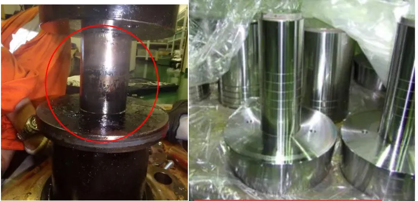
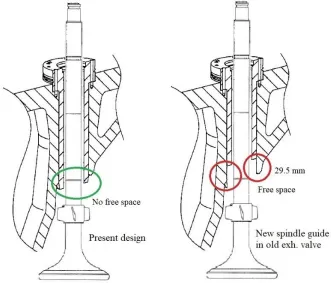
f.Measures from manufacturer
• Replace hydraulic hose connectors to increase sealing and loosening capabilities;
• Replace hydraulic hoses with larger diameters;
• Replace the conduit guide pipe to increase heat transfer capability. The essential feature of the new design is the shorter guide pipe, the larger inner diameter.
Fig. 8: Space when changing the guide pipe according to the new design
g.Proposed measures
Discharge of air thoroughly at lubricating oil locations, self-discharge filter, fine filter before hydraulic pump intake.
Enhance the hydraulic oil leakage test in pipelines from HCU to MEV piston.
Periodically check the pressure of the energy tank in the stop engine state, if necessary. For accurate results, it is necessary to fully discharge the remaining hydraulic oil pressure in the system and have the temperature adjusted. Strengthen the leakage test of the spring wind in the air cylinder, the check valve on the supply (check in the engine stop state), recommend every 3 months. Abrasion on the cuff on the air cylinder or may result in the possibility of spring gas leakage, resulting in a change in the time of opening or opening of the cylinder, or a non-flammable
cylinder due to incomplete closure, causing fungal damage, rolling valve because the valve does not close.
Enhance leakage test in "gas spring," the check valve on the exhaust valve (check-in engine stop state), recommend every 3 months. Abrasion on the seal on "air cylinder" or may lead to leakage of "gas springs," resulting in the time of closing, opening the valve is changed, or the cylinder does not burn due to the incomplete valve, causing fungal damage, rolling valve due to the valve does not close. The process of checking the tightness of the "air cylinder" on the valve in the engine stop state (no need to remove the cylinder) as follows:
~ 114 ~ - Stop pumping engine lubricant (oil level to valve)
- Set the indicator bar of valves in the free position, mark this position.
- Close the air supply valve for the "gas spring" to the valve, exhaust the pipe. Calculate the time from the exhaust on the pipeline until the indicator bar of the valve starts to go down, meaning that the discharge starts to open.
- If the measuring time is greater than 15 minutes, the sealing capacity of the "air cylinder" and the check valve is still functional.
- If this time is less than 15 minutes, the valve should be cured as soon as possible, replacing damaged parts (such as shoots of cylinders, one-way valves, valve seals or safety valves).
Check the surface state of the tip, the working part with the maintenance guide pipe to see the level of fouling, soot, fire, and wear (if any).
Check the condition of the seal and throttle holes on the top of the valve during maintenance.
Monitor the impact of MEV-piston on the display screen and the position of the ELFI control valve.
The valve replacement process should take into account the “air spring” level before running the lubricant pump. Otherwise, the value of the closed and open corners of the valve may be changed.
4. Conclusion
It should be determined that the marine engine operation at a low load operation (especially 40% or less) is not conducive to the operation of the engine and related equipment. However, manufacturers accept and allow the engine to operate continuously at such a low load condition. The mode operates at a low load of marine engines that drive the propeller is used quite recently in various reasons. The S46 ME-B8.5 engine concept consists of a hydraulic-mechanical system for activation of the fuel injection. The fuel pressure booster consists of a simple plunger powered by a hydraulic piston activated by oil pressure. An electronically controlled proportional valve controls the oil pressure. The exhaust valve is activated by a light camshaft, driven by a chain drive placed in the aft end of the engine. However, at low load operation, the MAN B&W S46ME-B8.5 engines have generated several incidents that greatly affect the operation of the ship including a malfunction on the exhaust valve and troubles of jamming plungers of the high-pressure pump during engine acceleration and start-up. Therefore, it is essential to learn and identify structural and operational characteristics of the S46 ME-B8.5 engines. Moreover, it is necessary to analyze the effects on the process of low-load operation as sailing. The paper focuses on studying the operating characteristics of engines in low load mode, assessing the effects of this mode on engines and related machines. Besides, this study also developed the operation process for S46ME-B8.5 engines. In this paper, the authors propose solutions to effectively operate the S46 ME-B8.5 engines in low load mode when traveling on the sea.
References
1. D. Woodyard and D. Woodyard, “Chapter Thirteen –
Burmeister & Wain Low-Speed Engines,” in
Pounder’s Marine Diesel Engines and Gas Turbines,
2009.
2. B. Yang, G. Song, L. Shen, Y. A. Ghuktomova, and J.
Xu, “Fault Diagnosis Method for Internal Combustion
Engines Based on IHS-RVM Model,” J. Mech. Eng.
Res. Dev., vol. 40, no. 1, pp. 64–71, 2017.
3. A. T. Hoang and V. D. Tran, “Experimental analysis on the ultrasound-based mixing technique applied to ultra-low sulphur diesel and bio-oils,” Int. J. Adv. Sci.
Eng. Inf. Technol., vol. 9, no. 1, pp. 307–313, 2019.
4. L. R. Juliussen, M. J. Kryger, and A. Andreasen, “MAN B & W ME-GI Engines. Recent Research AND
RESULTS,” in Proceedings of the International
Symposium on Marine Engineering (ISME) October,
2011.
5. M. I. Lamas and C. G. Rodríguez Vidal,
“Computational Fluid Dynamics Analysis of the Scavenging Process in the MAN B&W 7S50MC Two-Stroke Marine Diesel Engine,” J. Sh. Res., 2012.
6. A. T. Hoang and V. V. Pham, “Impact of jatropha oil
on engine performance, emission characteristics, deposit formation, and lubricating oil degradation,”
Combust. Sci. Technol., vol. 191, no. 03, pp. 504–519,
2019.
7. X. D. Pham, A. T. Hoang, D. N. Nguyen, and V. V Le,
“Effect of Factors on the Hydrogen Composition in the Carburizing Process,” Int. J. Appl. Eng. Res., vol. 12, no. 19, pp. 8238–8244, 2017.
8. A. T. Hoang, V. D. Tran, V. H. Dong, and A. T. Le, “An experimental analysis on physical properties and
spray characteristics of an ultrasound-assisted
emulsion of ultra-low-sulphur diesel and Jatropha-based biodiesel,” J. Mar. Eng. Technol., pp. 1–9, 2019. https://doi.org/10.1080/20464177.2019.1595355.
9. V. V. Pham and D. T. Cao, “A brief review of
technology solutions on fuel injection system of diesel engine to increase the power and reduce environmental pollution,” J. Mech. Eng. Res. Dev., vol. 42, no. 1, pp. 01–09, 2019.
10. V. V. Pham, “Research on the application of Diesel-Rk
in the calculation and evaluation of technical and economic criteria of marine diesel engines using the unified ULSD and Biodiesel blended fuel,” J. Mech.
Eng. Res. Dev., vol. 42, no. 2, pp. 87–97, 2019.
11. A. T. Hoang and V. V. Pham, “A review on fuels used
for marine diesel engines,” J. Mech. Eng. Res. Dev., vol. 41, no. 4, pp. 22–32, 2018.
12. A. T. Hoang, Q. V. Tran, A. R. M. S. Al-Tawaha, V. V. Pham, and X. P. Nguyen, “Comparative analysis on performance and emission characteristics of an in-Vietnam popular 4-stroke motorcycle engine running on biogasoline and mineral gasoline,” Renew. Energy
Focus, vol. 28, pp. 47–55, 2019.
13. H. N. Psaraftis and C. A. Kontovas, “Speed models for energy-efficient maritime transportation: A taxonomy and survey,” Transp. Res. Part C Emerg. Technol., 2013.
14. T. Tezdogan, Y. K. Demirel, P. Kellett, M.
Khorasanchi, A. Incecik, and O. Turan, “Full-scale unsteady RANS CFD simulations of ship behaviour and performance in head seas due to slow steaming,”
Ocean Eng., 2015.
15. T. Tezdogan, A. Incecik, O. Turan, and P. Kellett, “Assessing the Impact of a Slow Steaming Approach on Reducing the Fuel Consumption of a Containership
Advancing in Head Seas,” in Transportation Research
Procedia, 2016.
~ 115 ~ of a diesel engine running on preheated vegetable oil and diesel oil,” Energy Sources, Part A Recover. Util.
Environ. Eff., vol. 41, no. 5, pp. 611–625, 2019.
17. M. Setiyo, S. Soeparman, N. Hamidi, and S. Wahyudi,
“Cooling effect characteristics of a ½ cycle refrigeration system on an LPG fuel system,” Int. J.
Refrig., 2017.
18. N. Hu, P. Zhou, and J. Yang, “Reducing emissions by
optimising the fuel injector match with the combustion chamber geometry for a marine medium-speed diesel engine,” Transp. Res. Part D Transp. Environ., 2017.
19. Anon, “High efficiency turbocharging system from
ABB Turbo Systems,” Diesel Gas Turbine Worldw., 1989.
![Fig. 2: Exhaust valve status when operating continuously at low load[20]](https://thumb-us.123doks.com/thumbv2/123dok_us/7825065.1665839/4.595.87.515.599.771/fig-exhaust-valve-status-operating-continuously-low-load.webp)
![Fig. 5: Nozzle and impact on the seat of the exhaust valve [18]](https://thumb-us.123doks.com/thumbv2/123dok_us/7825065.1665839/5.595.88.511.444.603/fig-nozzle-impact-seat-exhaust-valve.webp)