Abstract— Making an Autonomous Electric Vehicle (AEV) and able to operate “unmanned” requires extensive theoretical as well as practical knowledge. An AEV must be able to make decisions and respond to situations completely on its own. Buggy car are used a as Electric Vehicle (EV) and set up with several equipment and sensor as an AEV. A camera is installed in front of the AEV and is used to obtain image information of the road. On the other hand, users or drivers do not have to directly contact with the main system because it will autonomously control the devices by using fuzzy information of the road conditions. This paper focuses on experimental used on vision system of AEV. From the experimental results, the AEV has demonstrated a robust performance for moving in straight line on line detection vision navigation.
Index Term— Autonomous Electric Vehicle (AEV), Vision System, Line Detection.
I. INTRODUCTION
Autonomous driving is increasingly attracting public interest due to various research projects over the past years [1-7]. Usually, conventional cars are converted with significant effort and many different sensors are placed on the roof. The advance of electro-mobility provides the chance for completely new vehicle concepts. By breaking away from classic approaches, it is possible to consider and integrate autonomous driving into the vehicle architecture with respect to IT and sensor systems, energy management and design. These kinds of cars are the upgrade version of electric vehicle (EV). Recently a lot of EVs and related vehicles such as a hybrid car have been developed to solve environment and
Paper submitted on 10 Mac 2014. This work is supported by Majlis Amanah Rakyat (MARA) and supported by the fundamental research grant scheme (FRGS) awarded by the Ministry of Higher Education to Universiti
Malaysia Perlis (FRGS 9003-00313).
Hasri Haris, Bahagian Sumber Manusia, Tingkat 17 & 18, Ibu Pejabat MARA Jalan Raja Laut, 50609 Kuala Lumpur, MALAYSIA and Advanced
Intelligent Computing and Sustainability Research Group, School of Mechatronic, Universiti Malaysia Perlis Kampus Pauh Putra, 02600 Arau,
Perlis, MALAYSIA (e-mail: [email protected]).
Khairunizam WAN, Centre of Excellence for Unmanned Aerial System (COEUAS) and Advanced Intelligent Computing and Sustainability Research
Group, School of Mechatronic, Universiti Malaysia Perlis Kampus Pauh Putra, 02600 Arau, Perlis, MALAYSIA (e-mail:
Kamil S. Talha, Advanced Intelligent Computing and Sustainability Research Group, School of Mechatronic, Universiti Malaysia Perlis Kampus
Pauh Putra, 02600 Arau, Perlis, MALAYSIA (e-mail: [email protected]).
energy problems caused by the use of an internal combustion engine vehicle. Developing such vehicles for solving the environment and energy problems is a great idea. Currently, many researches publish technical papers in journals, which are related to autonomous EV. In their researches, steering wheel, brake and acceleration pedals are control by using computers [8-10]. On the other hand, users and drivers do not have a direct contact with them. A touch panel is installed in the EV and it serves a user Graphical User Interface (GUI) for users and drivers interact with controlling devices. Unfortunately, based on current outcomes more effort should be done for making sure that autonomous EV could move with safety. Although mechanism of mechanical could be used to solve safety and reliability issues of autonomous EV, computational approach also very important. The computational approach is for example the algorithm for controlling motor device, the capacity of data transmission device, image processing technique and etc. [11-13]. Autonomous vehicle with intelligent driving control are developed to provide the driver assistance as well as unmanned driver for road, logistics and flexible manufacturing system. It is an automatic guided vehicle and able to move automatically along the road. This research will focus on design and implementation of a sensor fusion system for navigation and control of an autonomous electric vehicle. It also introduced the intelligent vehicle trace, obstacle avoidance and speed control. In the first part, a vision system for the electric vehicle will be develop by using image processing techniques to recognize neighboring circumstances surrounding the electric vehicle.
This research paper is organized as follows; Section 2 assessing the literature reviews of vision system for lane detection. Section 3 presents the methodology of applied system. Section 4 is divided into two sections, first are about the experiment setup done while the second section demonstrated the result of the experiments. Finally, section 5 will express the overall conclusions over the current research.
II. LITERATURE REVIEW
Vision system for lane lines detection is one important process based driver assistance system and can be used for vehicle navigation, collision prevention, lateral control, or lane lines departure warning system. Various road conditions make this problem become very challenging including different type of lane lines (straight or curvilinear), obstacles, lighting
Vision-based Path Estimation for the
Navigation of Autonomous Electric Vehicle
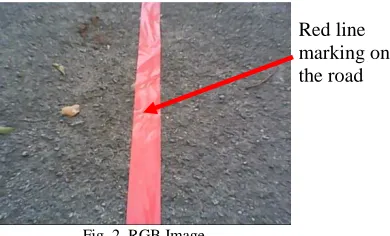
Red line marking on the road changes (night time), occlusions caused by shadows, and so
on. Therefore, in the literature and recently, there have been many approaches proposed for solving the above problems in lane lines detection. For example, Cheng et al. [14] used the colour feature to detect lane and utilized the size, shape and motion for false lane region elimination. He et al. [15] proposed a colour-based vision system to detect lanes from urban traffic scenes. Yim and Oh [16] combined three features including the starting position, intensity, and direction for lane detection. In addition to the feature-based scheme, the model-based scheme is more robust in lane detection when different lane types with occlusions or shadows are handled. Kang and Jung [17] proposed a searching framework to group edges with similar directions as a road lane. However, when complicated roads were handled, their method tended to detect false candidates of lane. In Kluge and Lakshmanan [18], a deformable template model of lane structure is used to locate lane boundaries by using intensity gradient information. Jung and Kelber [19], used an approach that combines an edge distribution function and the Hough transform with linear parabolic model is developed for lane detection and lane tracking. Hechri et. al. [20], the Hough transform is very powerful because it can detect road boundaries successfully even in an extremely snowy environment.
III. METHODOLOGY
A. Flow chart of the proposed works
Fig. 1. Flow chart of proposed works
B. RGB Image Acquisition
For the line detection, first vision acquisition setup has been made. Webcam with the resolution of 640 x 480 had been chosen. Image that produces from webcam is in RGB color plane. By using the graphical function in Lab VIEW, image from the RGB color space can be converted to several color spaces. The best color plane in detection of the line will be choosing to convert to gray scale image. For this research, we choose red color plane as the line color. In the gray scale
image, the threshold value for the line will be determine for extracting line region in binary image.
The input data is a color image sequence taken from a moving vehicle. A color camera is mounted in-front of the electric vehicle. It takes the images of the environment in front of the vehicle. The on-board computer with image capturing card will capture the images in real time (up to 30 frames/second), and save them in the computer memory. The lane detection system reads the image sequence from the memory and starts processing. A typical scene of the road ahead is depicted by Fig. 2. In order to obtain good estimates of lanes and improve the speed of the algorithm, the original image size was reduced to 620x480 pixels by Gaussian pyramid.
Fig. 2. RGB Image
C. Converting to Gray Scale
To retain the color information and segment the road from the lane boundaries using the color information this proved difficulties on edge detection and also it will affect the processing time. In practice the road surface can be made up of many different colors due to shadows, different pavement style or age, which causes the color of the road surface and lane markings to change from one image region to another. Therefore, color image are converted into gray scale. However, the processing of gray scale images becomes 84 minimal as compared to a color image. This function transforms a 24-bit, three-channel, color image to an 8- bit, single-channel gray scale image by forming a weighted sum of the Red component of the pixel value * 0.3 + Green component of the pixel value * 0.59 + Blue component for the pixel value *0.11 the output is the gray scale value for the corresponding pixel.
Fig. 3. Gray scale Image
Control Circuit Control Circuit Converting to Gray Scale Image
Converting to Binary Image
Edge Detection RGB Image Acquisition
Measure Distance (dL, dR)
D. Converting to Binary Image
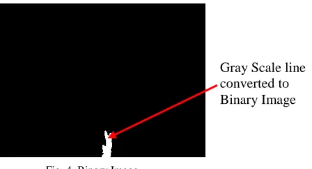
A binary image is a digital image that has only two possible values for each pixel. Typically the two colors used for a binary image are black and white though any two colors can be used. The color used for the object(s) in the image is the foreground color while the rest of the image is the background color. In the document-scanning industry this is often referred to as "bi-tonal".
A binary image can be stored in memory as a bitmap, a packed array of bits. A 640×480 image requires 37.5 KiB of storage. Because of the small size of the image files, fax machine and document management solutions usually use this format. Most binary images also compress well with simple run-length compression schemes.
Binary images can be interpreted as subsets of the two-dimensional integer lattice Z2; the field of morphological image processing was largely inspired by this view. Fig. 4 shows the image after conversion to binary Image.
Fig. 4. Binary Image
E. Edge Detection
Lane boundaries are defined by sharp contrast between the road surface and painted lines or some type of non-pavement surface. These sharp contrasts are edges in the image. Therefore edge detectors are very important in determining the location of lane boundaries. It also reduces the amount of learning data required by simplifying the image considerably, if the outline of a road can be extracted from the image. The edge detector implemented for this algorithm and the one that produced the best edge images from all the edge detectors evaluated was the ‗canny‘ edge detector [14]. To find the maxima of the partial derivative of the image function I in the direction orthogonal to the edge direction, and to smooth the signal along the edge direction.
The Sobel operator is used in image processing, particularly within edge detection algorithms. Technically, it is a discrete differentiation operator, computing an approximation of the gradient of the image intensity function. At each point in the image, the result of the Sobel operator is either the corresponding gradient vector or the norm of this vector. The Sobel operator is based on convolving the image with a small, separable, and integer valued filter in horizontal and vertical direction and is therefore relatively inexpensive in terms of computations. On the other hand, the gradient approximation
that it produces is relatively crude, in particular for high frequency variations in the image. The Kayyali operator for edge detection is another operator generated from Sobel operator.
The operator uses two 3×3 kernels which are convolved with the original image to calculate approximations of the derivatives - one for horizontal changes, and one for vertical. If we define A as the source image, and Gx and Gy are two images which at each point contain the horizontal and vertical derivative approximations, the computations are as follows:
[
] [
]
where here denotes the 2-dimensional convolution operation.
Since the Sobel kernels can be decomposed as the products of an averaging and a differentiation kernel, they compute the gradient with smoothing. For example, Gx can be written as
[
] [ ] [ ]
The x-coordinate is defined here as increasing in the "right"-direction, and the y-coordinate is defined as increasing in the "down"-direction. At each point in the image, the resulting gradient approximations can be combined to give the gradient magnitude, using:
√
Using this information, we can also calculate the gradient's direction:
( )
where, for example, is 0 for a vertical edge which is darker on the right side.
F. Measure Distance (dL, dR)
The IMAQ Clamp Horizontal Max VI will measure a distance in the horizontal direction, from the vertical sides of the search area towards the center of the search area. This VI locates edges along a set of parallel search lines, or rake. The edges are determined based on their contrast and slope.
A vertical hit-line to the object is calculated through the leftmost edge detected. A second vertical hit-line to the object is calculated through the rightmost edge. The distance between those two lines is returned. IMAQ Clamp Horizontal Max can overlay on the image returned: the position of the search area, the search lines, the edges found, and the result. Gray Scale line
Fig. 5. Theoritical Frame for Distance dL and dR
Fig. 5 show the theoretical frame to get the distance of dL and dR. Where F is the size of camera frame to captured line on the road. ddis the distance inside the line or width of the line. dL is the distance from left frame to the line. dR is the distance from the right frame to the line. dy is the distance from the left frame to the CoG. And CoG is the center of the gravity of the line.
Based on CoG, dL is defined by the following distance equation;
(1) and, ( ) (2)
Where F = 640 (size of the frame)
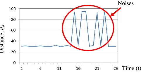
To filtering the noise from the graph, is defined by the following filtering equation;
If (3)
And we assume that value of,
IV. EXPERIMENTS
A. Experimental Setup
To test and evaluate the proposed methodology on EV vision in Chapter 3, the Buggy Car have been used and set up as stated on system configuration. Fig. 6 show the buggy car used in the experiments. This setup has been made at Putra Golf Club, Sungai Batu Pahat, Perlis. In the experiment, the camera mounted in front of Buggy Car with noise reduction.
Fig. 6. Buggy Car used in Experiments
This camera will detect the red line, which have been marking on the road while Buggy Car moved. The image captured will be send to computer (PC1). A Lab View 2012 was used as software to process the image as stated in methodology (EV Vision).
Table I Experimental Parameters
Parameter Characteristic
Target Distance 5 meters
Time 30 second
Trial 10 times
Line Width 6 cm
B. Experimental Results
(b) Screen shot of Tracking Image displayed at the touch panel
Fig. 7. Autonomous EV Controller Interface displayed at the touch panel
Fig. 7(a), show the screen shot of preprocessing the input image of the line captured and converting to Gray scale and Threshold Gray scale Image in the Lab View. And fig. 7(b) is the screen shot of the tracking image to get distance, dL and
dR.
From the data of the experiments, we have plot the graph to show AEV move.
Fig. 8. Trajectories of line distance, dd with noise.
Fig. 9. Trajectories of line distance, dd after filtering.
Fig. 8. shows trajectories of raw line distance dd with noise and Fig.9 show trajectories of line distance dd after filtering. From the results, to make the AEV move in straight line, it should be filtered.
Fig. 10. Trajectories of line distance for dy and dL
V. CONCLUSION AND FUTURE WORK
This paper presents the design and implementation of an autonomous Electric Vehicle (EV) with intelligent driving control to provide the driver assistance as well as unmanned driver. It is an automatic guided vehicle and able to move automatically along the tracks in a given region. For the purpose of prototyping, a buggy car has been used and several sensors are installed. The camera has been installed to the EV as a vision system and connects to the personal computer (PC) for the processing of image information. Image processing algorithm will be employed for the detection of line and the center of gravity (COG) of the road. For the future research, another PC will be installed for controlling motors to operate acceleration pedal, brake pedal and steering wheel. Information from several sensors was fused to move the EV intelligently without control by the human.
ACKNOWLEDGMENT
Special thanks to all members of UniMAP Advanced Intelligent Computing and Sustainability Research Group and School Of Mechatronics Engineering, University Malaysia Perlis (UniMAP) for providing the research equipment‘s and internal foundations. This work was supported by the Majlis Amanah Rakyat (MARA) and fundamental research grant scheme (FRGS) awarded by the Ministry of Higher Education to University Malaysia Perlis (FRGS 9003-00313).
REFERENCES
[1] P.E Dumont, A Aitouche and M. Bayart, ―Fault Tolerant Analysis for Multisensor Non Linear Systems‖, Application to An Autonomous Vehicle (IEEE Vehicle Power and Propulsion), p198-203, 2004. [2] II Hammouri, M Kinnaert and E H El Yaagoubi, ―Observer-Based
Approach to Fault Detection and Isolation for Nonlinear Systems‖, Noises
Time (t)
Dis
tan
ce
,
dd
Dis
tan
ce
,
dd
Time (t)
Distance, dy
(IEEE Transactions on Automatic Control), vol 44, (No. l0) p 1879-1884, 1999.
[3] M. A. Djeziri, A. Aitouche and B. Ould Bouamama, ―Sensor Fault Detection Of Energitic System Using Modified Parity Space Approach‖, IEEE Conference on Decision and Control, p 2578-2583, 2007. [4] K. Bouibed, A. Aitouche and M. Bayart, ―Nonlinear Parity Space
Applied to an Autonomous Vehicle‖, Journal of Energy and Power Engineering ISSN 1934-8975, Vol. 3 (No 12), (Serial No.25) p 10-18, 2009.
[5] M. A. Djeziri, R. Merzouki and B. Ould Bouamama, ―Robust Monitoring of Electric Vehicle with Structured and Unstructured Uncertainties‖, IEEE Transaction on Vehicular Technology, ISSN 0018-9545, Vol. 58 (No. 9), p 4710-4719, 2009.
[6] Han-Shue Tan, Rajesh Rajamani and Wei-Bin Zlhang, ―Demonstration of an Automated Highway Platoon System‖, Proceedings of the American Control, 1998.
[7] Systems Control Technology Inc. ―Roadway Powered Vehicle Project rack Construction and Testing Program Phase 3D‖, California PATH Research Paper, 1994.
[8] S. R. Cikanek and K. E. Bailey, ―Regenerative Braking System for A Hybrid Electric Vehicle‖, Proceedings of the American Control Conference Anchorage, 2002.
[9] H. X. Li and S. Guan, ―Hybrid Intelligent Control Strategy: supervising a DCS-controlled batch process‖, IEEE Control Systems Magazine 21(3), 2001.
[10] CHEN Quan-Shi, QIU Bin and XIE Qi-Cheng, ―Fuel Cell Electric Vehicle‖, Tsinghua University Press, 2005.
[11] Howlett P.G., Pudney P.J. and Xuan Vu, ―Local Energy Minimization in Optimal Train Control‖, Journal of Automatica, Vol. 45 (No. 11), p 2692-2698, 2009.
[12] General Definitions of Highspeed, International Union of Railways, 2009.
[13] Masamichi Ogasa, ―Energy Saving and Environmental Measures in Railway Technologies: Example with Hybrid Electric Railway Vehicles‖, IEEJ Trans. on Electrical and Electronic Engineering, Vol. 3 (No.5), p 304-311, 2010.
[14] H. Y. Cheng, et al., "Lane detection with moving vehicle in the traffic scenes". IEEE Transactions on ITS, Vol. 7, pp. 571-582, 2006. [15] Y. He, H. Wang, and B. Zhang, "Color-Based Road Detection in Urban
Traffic Scenes". IEEE Transactions on ITS, vol. 5, pp. 309-318, 2004. [16] Y. U. Yim and S. Y. Oh, "Three-Feature Base Automatic Lane
Detection Algorithm (TFALDA) for Autonomous Driving". IEEE Transaction on ITS, vol. pp. 219-225, 2003.
[17] D. J. Kang, M. H. Jung "Road lane segmentation using dynamic programming for active safety vehicles". Pattern Recognition Letters, Vol. 24, Issue 16, pp. 3177-3185, 2003.
[18] K. Kluge and S. Lakshmanan, "A deformable template approach to lane detection". IEEE Intelligent Vehicle Symposium, pp.54-59, Sept. 1995. [19] C.R. Jung and C.R. Kelber, "A robust linear-parabolic model for lane
following". The XVII Brazilian Symposium on Computer Graphics and Image Processing, 2004.
[20] Ahmed Hechri, Fayçal Hamdaoui, Anis Ladgham and Mtibaa Abdellatif, "Using fuzzy logic path tracking for an autonomous robot". In International Review of Automatic Control - Theory and Applications (IREACO), Praise Worthy Prize Publishers (Italy), (ISSN: 1974 – 6059) Volume 4 (Issue 1).
[21] Hasri Haris and Khairunizam Wan, ―A Fusion of Sensors Information for Autonomous Driving Control of an Electric Vehicle (EV)‖, IOP Conference Series: Materials Science and Engineering, Vol. 53, No.01 pp. 20-25, 2013.
[22] M. Aly, ―Real Time Detection of Lane Markers in Urban Streets‖, Intelligent Vehicles Symposium, p 7-12, 2008.
[23] A. Hechri and A. Mtibaa, ―Lanes and Road Signs Recognition for Driver Assistance System‖, International Journal of Computer Science, Vol. 8 (No.6), 2011.
Hasri Haris received his Bachelor Engineering (Hons) in Electrical Engineering from University Teknologi Malaysia (UTM) in 1998 and Master in Technical Education (Electronic Industrial) from University Tun Hussein Onn (UTHM) in 2008. He is currently a PhD student at University Malaysia Perlis. His research interest is in Intelligent Transportation System, Artificial Intelligence and Robotics.
Khairunizam WAN received his B. Eng. degree in Electrical & Electronic Eng. from Yamaguchi University and Ph.D. in Mechatronic Eng. from Kagawa University, in 1999 and 2009 respectively. He is currently a Senior Lecturer at School Of Mechatronic Engineering, University Malaysia Perlis. He is member of Board of Engineer and Institute of Engineer, Malaysia. His research interest is in Human-Computer Interaction (HCI), Intelligent Transportation System, Artificial Intelligence and Robotics.