Automatic Accident Detection, Ambulance Rescue
And Traffic Signal Controller
Vignesh.M M.Ishwarya Niranjana
Assistant Professor Assistant Professor
Department of Electronics & Communication Engineering Department of Electronics & Communication Engineering Pollachi Institute of Engineering & Technology, Coimbatore Pollachi Institute of Engineering & Technology, Coimbatore
Manikandan.R Suganthan.S
UG Student UG Student
Department of Electronics & Communication Engineering Department of Electronics & Communication Engineering Pollachi Institute of Engineering & Technology, Coimbatore Pollachi Institute of Engineering & Technology, Coimbatore
Malayandisamy.P
UG Student
Department of Electronics & Communication Engineering Pollachi Institute of Engineering & Technology, Coimbatore
Abstract
Traffic accidents are one of the leading causes of fatalities in the all places. An important indicator of survival rates after an accident is the time between the accident and when emergency medical personnel are dispatched to the scene. One approach to eliminating the delay between accident occurrence and first responder dispatch is to use in-vehicle automatic accident detection and notification systems, which sense when traffic accidents occur and immediately notify emergency personnel. This project aims at finding the occurrence of any accident and reporting the location of accident to the nearest ambulance, so that immediate help can be provided by ambulance. And the ambulance reach the traffic signal the ambulance driver controls the signal. Intimating the traffic control section regarding the direction of ambulance GSM technology is used to intimate the vehicle position in the form of latitude and longitude coordinates through internet. The location spot is retrieved using Global Positioning System which is a navigational system using a network of satellites orbiting the earth. Sensors such as vibration and airbag detect signal in case of an accident occurrence and send a signal to the connected microcontroller. This paper describes the accident detection and intimating the incident to ambulance services spontaneously and these in vehicle systems, however, are not available in all cars and are expensive to retrofit for older vehicles. This project provides the result by Smartphone accident detection system to prevent false positives.
Keywords: Ambulance, GPS, GSM, Microcontroller, Traffic control, Vibration Sensor
________________________________________________________________________________________________________
I. INTRODUCTION
II. EXISTING SYSTEM
Manual Controlling
Manual controlling the name instance it require man power to control the traffic. Depending on the countries and states the traffic polices are allotted for a required area or city to control traffic. The traffic polices will carry sign board, sign light and whistle to control the traffic. They will be instructed to wear specific uniforms in order to control the traffic.
Automatic Controlling
Automatic traffic light is controlled by timers and electrical sensors. In traffic light each phase a constant numerical value loaded in the timer. The lights are automatically getting ON and OFF depending on the timer value changes. While using electrical sensors it will capture the availability of the vehicle and signals on each phase, depending on the signal the lights automatically switch ON and OFF.
III. PROPOSED SYSTEM
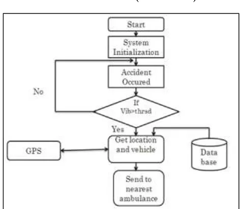
In proposed system if a vehicle has met accidents, immediately an alert message with the location coordinates is sent to the Control center. From the control center, a message is sent to the nearby ambulance. Also signal is transmitted to all the signals in between ambulance and vehicle location to provide RF communication between ambulance and traffic section. The vehicle accident observed using vibration sensor and in the control section it is received by the microcontroller and then the nearby ambulance is received from the PC and controller sends the message to the ambulance. The signal to Traffic signal section is transmitted through RF communication. Also if any fire occurs, it is detected using fire sensor and an alarm message is directly sent to the fire station.
IV. BLOCK DIAGRAMS
Block Diagram of Vehicle Unit
If a vehicle has met accident, vibration sensor or fire sensor gives the electric signal to microcontroller through Signal conditioner. Then GPS provides latitude and longitude information about vehicle location to control section through GSM.
Fig. 1: Block diagram of vehicle unit
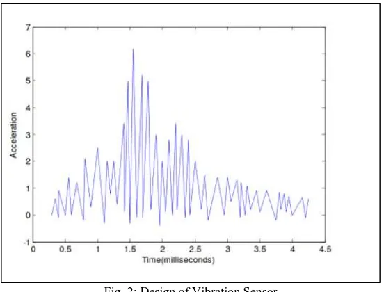
Vibration sensor
Fig. 2: Design of Vibration Sensor
The predefined data i.e. Peak voltage level or crash waveform data are used to decide whether an accident is occurred or not.The vibration sensor used in the vehicle will continuously sense for any large scale vibration in the vehicle. The sensed data is given to the controller GPS SYSTEM inside the vehicle. The GPS SYSTEM finds out the current position of the vehicle (latitude and the longitude) which is the location of the accident spot and gives that data to the GSM MODULE. The GSM MODULE sends this data to the control unit whose GSM number is already there in the module as an emergency number. We can also use this vehicle unit for health monitoring of the patient using different sensors.
GPS (Global Positioning System)
It stands for “Global positioning system”. It is having 24 satellites it will transmit the coded information. These 24 satellites will rotate one time over the earth in every 12 hours. In order to provide the information about velocity, time etc… GPS will help us identify the distance between the two different places on the earth and it will show the route to reach the required destination. Figure 2 shows the GPS module. There are three different segments in GPS they are:
1) Space segment 2) Control segment 3) User segment
When satellites transmit information and each satellite will have a different code and it also transmit information at different frequencies so that the GPS can discriminate with the different signal received by the different satellites. This condition will help to calculate the time taken to travel the distance between the satellite and the GPS receivers and then the travel time is multiplied by the light speed gives the distance between the satellite and the GPS receiver The control segment will identify the satellite and it will guide with the proper orbit and proper time taken by the satellite to reach the GPS.
It is having four unmanned station with single master control station. These unmanned stations will receive the information from different satellites and this information is send to the master station and this is send to the GPS satellite. The user segments consist of users and the GPS receivers. Working of GPS: When a GPS receiver is started to work, firstly it will start to download the orbit information about each and every satellite to download this information it will take around 12.5 min once this information is completely downloaded it will be stored in the receivers in order to use further. The GPS knows the exact location of the satellite but still it needs to know the exact distance between the satellite and the receiver. This distance can be calculated by the receiver, by multiplying the time taken by the signal to reach the receiver and the velocity of the transmitted signal. But the receiver already knows the velocity which is 18600 miles/ sec.
Block Diagram of Ambulance/Control Unit
Fig. 4: Block Diagram of Ambulance/Control Unit
In control section GSM modem receives message about accident and send it to PC. PC identifies the nearest ambulance and ambulance is instructed to pick up the patient. Control section transmits the control signal to all the signals in between ambulance and vehicle by RF transmission.
Block Diagram of Traffic Unit
Fig. 5: Block Diagram of traffic unit
Whenever the ambulance reaches near to the traffic signal(approximately 100m), the traffic signal will be made to green through RF communication. Thereby the ambulance is recommended to reach the hospital in time.
V. SYSTEM IMPLEMENTATION
Our system consists of three main units, which coordinates with each other and makes sure that ambulance reaches the hospital without any time lag. Thus our system is divided into following three units,
1) The Vehicle Unit
2) The Ambulance/control Unit 3) Traffic unit
Vehicle unit
GSM MODULE. The GSM MODULE sends this data to the control unit whose GSM number is already there in the module as an emergency number.
Ambulance unit
The controller finds the nearest ambulance to the accident spot and also the shortest path between the ambulance, accident spot and the nearest hospital. The controller then sends this path to the ambulance. Also using this information the controller controls all the traffic signals in the path of ambulance and makes it ready to provide free path to ambulance, which ensures that the ambulance reaches the hospital without delay. At the same time, the ambulance unit turns ON the RF transmitter. This will lead to communicate with the traffic section.
Traffic unit
Whenever traffic signal section receives the information about accident, the RF receiver in this section is turned ON to search for ambulance nearing the traffic signal. Whenever the ambulance reaches near to the traffic signal(approximately 100m), the traffic signal will be made to green through RF communication. Thereby the ambulance is recommended to reach the hospital in time.
RF Transmitter and Receiver
In generally, the wireless systems designer has two overriding constraints: it must operate over a certain distance and transfer a certain amount of information within a data rate. The RF modules are very small in dimension and have a wide operating voltage range i.e. 3V to 12V.
Fig. 6: Pin Diagram of RF Transmitter and Receiver
Basically the RF modules are 433 MHz RF transmitter and receiver modules. The transmitter draws no power when transmitting logic zero while fully suppressing the carrier frequency thus consume significantly low power in battery operation. When logic one is sent carrier is fully on to about 4.5mA with a 3volts power supply. The data is sent serially from the transmitter which is received by the tuned receiver. Transmitter and the receiver are duly interfaced to two microcontrollers for data transfer. Figure 3 shows the Pin Diagram of RF Transmitter and Receiver.
VI. METHODOLOGY (FLOWCHART)
Automatic accident detection using sensors, location tracking using GPS, sending location coordinates to ambulance, finding exact spot of accident using GPS viewer application, starting of rescue operation and traffic signal monitoring using RF transmitter and receiver all these steps are executed according to response of the circuit.
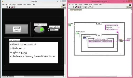
VII.SIMULATION RESULTS
Automatic Accident Detection and Ambulance Rescue with Intelligent Traffic Light System are simulated using PROTEUS SOFTWARE and their results are presented here. The circuit model of the above system is shown and sensors are connected to measure output result in normal condition the vibration sensor will be less than the present value. If a vehicle has met accident, vibration sensor gives the electric signal to microcontroller through signal conditioner. Then GPS provides latitude and longitude information about vehicle location to control section through GSM. If a vehicle has met accident, fire sensor gives the electric signal to microcontroller through signal conditioner. Then GPS provides latitude and longitude information about vehicle location to control section through GSM Before ambulance reaching the traffic signal junction, the signal will be red. Control section transmits the control signal to all the signals in between ambulance and vehicle by RF transmission. After ambulance reaching the traffic signal junction the signal will turn into green with the help of the RF signal.
Fig. 8: simulation output
VIII. CONCLUSION
In this paper, a novel idea is proposed for controlling the traffic signals in favor of ambulances during the accidents. With this system the ambulance can be maneuvered from the ITLS can be proved to be effectual to control not only ambulance but also authoritative vehicles. Thus ITLS if implemented in countries with large population like INDIA can produce better results. The ITLS is more accurate with no loss of time. But there may be a delay caused because of GSM messages since it is a queue based technique, which can be reduced by giving more priority to the messages communicated through the controller. INDIA can produce better results. The ITLS is more accurate with no loss of time. But there may be a delay caused because of GSM messages since it is a queue based technique, which can be reduced by giving more priority to the messages communicated through the controller.
REFERENCES
[1] Mr.S.Iyyappan ,V.Nandagopal “Accident detection and ambulance rescue with intelligent traffic light system” International Journal of advanced Research
in EEIE-2013.
[2] K.Sangeetha, P.Archana, M.Ramya , P.Ramya “Automatic Ambulance Rescue with Intelligent Traffic Light System”
International organization of scientific Research journal of Engineering-2014
[3] Mr. Sahil Gadroo Mr. Pinkesh Jodhwani Mr. Gunveer Singh Mr. A. D. Londhe “Automatic accident detection and ambulance rescue system” International
journal of scientific &engineering research-2015
[4] Hrishikesh Murkut, Fazal Patil, Vishal Yadav, Meghana Deshpande “Automatic accident detection and rescue with ambulance”SSRG International journal
of ECE-2015
[6] M. Kuorilehto, M. Kohvakka, J. Suhonen, P. Hamalainen, M.Hannikainen, and T. Hamalainen, "Ultra-Low Energy Wireless Sensor Networks in Practice Theory", Realization and Deployment, John Wiley & Sons, Inc, 2007.
[7] N. Bulusu, "Wireless Sensor Networks", Artech House, Inc, 2005.
[8] M. Lee, C. Yao, H. Liu,” Passive Tag for Multi-carrier RFID Systems”, IEEE 17th International Conference on Parallel and Distributed Systems, 2011.
[9] Y. Khalil, M. Al-kariki, “Intelligent Traffic Light Flow Control System using Wireless Sensor Networks”, Journal of Information Science and Engineering,
26, 753-768 (2010) .
[10] R. Kannan , R. Nammily, S. Manoj , A. Vishwa, ” Wireless Vehicular Accident Detection and Reporting System”, International Conference on Mechanical
and Electrical Technology (ICMET 2010).
[11] T. Malik, S. Yi, S. Hongchi , “Adaptive Traffic light control with Wireless Sensor Networks”, (2007).
[12] C. Anuran, B. Saumya, C. Anirudh, “An Intelligent Traffic Control System using RFID”, IEEE, 2009.
[13] R. Kannan ,V. Mohan ,A . Mohanan, P. Leons, R. Shooja, A Vishwa, "Wireless Sensor Network for Vehicle Speed Monitoring and Traffic Routing System“, International Conference on Mechanical and Electrical Technology (ICMET 2010).
[14] P. Bartłomiej, “Performance Evaluation of Road Traffic Control using a Fuzzy Cellular Model “, 2011.
[15] Kale, Sarika Baburao, and Gajanan P. Dhok. “Embedded system for intelligent ambulance and traffic control management.” IJCER 2.2 (2013): 137-142
[16] Athavan,K, et al. “Automatic Ambulance Rescue System. “Advanced Computing & Communication Technologies (ACCT), 2012 Second International
Conference on IEEE 2012.
[17] Marikhu Ramesh, et al. “Police Eyes: Real world automated detection of traffic violations. “Electrical Engineering/Electronics, Computer,
Telecommunications and Information Technology (ECTI-CON), 2013 10th International Conference on IEEE 2013
[18] A Assum, Terje, et al. “Risk compensation- the case of road lightning. “Accident Analysis & Prevention 31.5 (1999): 545-553
[19] Kamal, Md Abdus Samad, et al. “A vehicle- intersection coordination scheme for smooth flows of traffic without using traffic lights. “Inrelligent Transportation System, IEEE Transactions on 16.3 (2015): 1136-1147
[20] Wei, Wang, and Fan Hanbo. “Traffic accident automation detection and remote alarm device. “Electric Information and Control Engineering (ICEICE),
2011 International Conference on IEEE, 2011
[21] Papageorgiou, Markos, et al. "Review of road traffic control strategies."Proceedings of the IEEE 91.12 (2003): 2043-2067.
[22] Chowdhury, Tandrima, Smriti Singh, and S. Maflin Shaby. "A Rescue System of an advanced ambulance using prioritized traffic switching.”Innovations in