Automatic Paper Counting Machine
Anju S. Chippy Susan Rajan
B. Tech Student B. Tech Student
Department of Electronics & Communication Engineering Department of Electronics & Communication Engineering Saintgits College Of Engineering,Kottayam,Kerala Saintgits College Of Engineering,Pathamuttom,Kottayam
Haritha H. Nijo Varghese Chacko
B. Tech Student B. Tech Student
Department of Electronics & Communication Engineering Department of Electronics & Communication Engineering Saintgits College Of Engineering,Pathamuttom,Kottayam Saintgits College Of Engineering,Pathamuttom,Kottayam
Er. Beena A.O.
Assistant Professor
Department of Electronics & Communication Engineering Saintgits College Of Engineering,Pathamuttom,Kottayam
Abstract
Automatic paper counting machine proposes the idea of fast and efficient counting of paper without human effort. The proposed paper counting machine uses the embedded system Arduino for the functioning of the machine. It uses a sensing technology to sense the count entered and sends the corresponding signals to the input terminals of the IC in the arduino board. The usage of arduino board makes the machine more accurate in functioning. The arduino board on receiving the signals sends signals to input pins of a display which shows the number of the papers counted. The usage of arduino makes the interfacing of the display and programming of the proposed project more convenient. The required count of papers can be counted out from a bundle by inputting the number. The automatic paper counting machine finds a numerous applications in many fields. This project is proposed as a remedial measure for the problem raised in the exam cell of the college (on counting papers like question and answer sheets) which was displayed as a bulletin within the campus on various notice boards welcoming remedial measures.
Keywords: Arduino,
________________________________________________________________________________________________________
I. INTRODUCTION
The earlier machines size is big they are used in industrial purpose only. Now day’s world growing fast that’s why we think a machine that saves our time and money for that we made a machine which counts the pages.
Automatic paper counting machine proposes the idea of fast and efficient counting of paper without human effort. The proposed paper counting machine uses the embedded system Arduino for the functioning of the machine. It uses a sensing technology to sense the count entered and sends the corresponding signals to the input terminals of the IC in the arduino board. The usage of arduino board makes the machine more accurate in functioning. The arduino board on receiving the signals sends signals to input pins of a display which shows the number of the papers counted. The usage of arduino makes the interfacing of the display and programming of the proposed project more convenient. The required count of papers can be counted out from a bundle by inputting the number.
II. SYSTEM WORKING
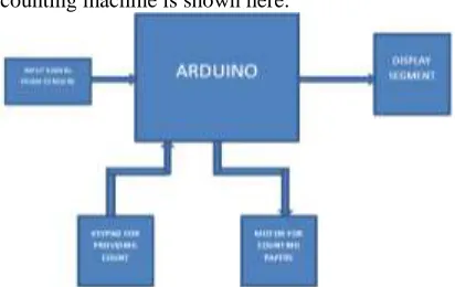
The block diagram of Automatic paper counting machine is shown here.
The basic working principle of paper counting and separating machine is from Xerox machine and currency counting machine. Paper counting machine consist of rotor, keypad, LCD display, tray switches, DC motor. In this machine first we insert the pages in middle side of prototype then user gives input by keypad. The LCD displays message or error message if any, with that command DC motor rotates that much rotation and counts the pages as well as sort out pages .These pages are collected in tray.
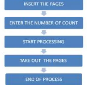
Fig. 2.2: Working Process There are two main subdivisions our machine works on
1) Separating. 2) Counting.
Our machine is basically a prototype for counting A4 size papers. The rotor is connected to the motor assembly. The rotor is used to separate the pages as it sticks to a page and helps to separate it out from the bunch.
1) Separating:
The pages to be sorted are loaded at the base fitted with springs to maintain adequate pressure on the bunch of papers to be sorted. The count of pages to be separated out from the bunch is given via 4X4 keypad interfaced with the microcontroller. The microcontroller then does the necessary processing and then displays the inputted count for separating the pages on the LCD. The time for which the motor will be rotating is programmed in way considering the length of the pages. The delay is specified by using c language. The number of pages to be sorted when given, the rotor connected to the motor rotates for the required time and the pages are collected in the collecting tray.
2) Counting:
We have used the concept of reverse engineering for the purpose of counting the pages. The pages which are supposed to be counted are loaded at the base. A random number is given just as a wild guess of number of pages in the bunch. When the count reaches the value of the random number the microcontroller executes the interrupt and stops the counting. The assembly also contains the a LDR and a LED when the pages loaded are over, the LDR senses the LED light and then executes the interrupt and stops the counting. The further process of counting works exactly as the process of separating.
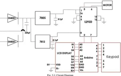
III. CIRCUIT DIAGRAM
Fig. 3.1: Circuit Diagram IV. COMPONENT DESCRIPTION
Arduino:
Roboduino ATmega328 board with cable comes from family of Arduino .Roboduino ATmega328 board with cable comes from family of Arduino boards can be bought online. Roboduino ATmega328 is a sophisticated board developed by RoboSpecies Technologies. Supports all kinds of Robotics projects and Embedded Systems Projects with easy made programming and debugging. Excellent physical computing supports all kinds of interfacing supports USB to Serial communication with FTDI chip and inbuilt ISP programming. It has 14 digital input/output pins (of which 6 can be used as PWM outputs),6 analog inputs, a 16 MHz crystal oscillator, a USB connection, a power jack, and a reset button. It contains everything needed to support the microcontroller; simply connect it to a computer with a USB cable or power it with a AC-to-DC adapter or battery to get started.
L293D:
L293D is a Motor driver integrated circuit which is used to drive DC motors rotating in either direction. It is a 16-pin IC which can control a set of two DC motors simultaneously. The L293D uses 5V for its own power and external power source is needed to drive the motors, which can be up to 36V and draw up to 600mA.
The L293D works on the concept of typical H-bridge, a circuit which allows the high voltage to be flown in either direction. In a single L293D IC there two H-bridge circuits which can rotate two DC motors independently. Due to its size and voltage requirement, it is frequently used in robotics applications for controlling DC motors, including in Arduino projects. The L293D is also a key component in larger 'motor driver' boards available premade for hobbyists.
There are two Enable pins on L293D. Pin 1 (left H-bridge) and pin 9 (right H-bridge). To drive the corresponding motor, pin 1 or 9 need to be set to HIGH. If either pin 1 or pin 9 goes low then the motor in the corresponding section will suspend working. The four Input pins for the L293D are pin 2 and 7 on the left and pin 15 and 10 on the right as shown on the pin diagram. Left input pins will regulate the rotation of motor connected on the left side and right input for motor on the right hand side. The motors are rotated on the basis of the inputs provided at the input pins as LOGIC 1 or LOGIC 0.
LCD Display:
A liquid-crystal display (LCD) is a flat-panel display or other electronic visual display that uses the light-modulating properties of liquid crystals. Liquid crystals do not emit light directly.
same basic technology, except that arbitrary images are made up of a large number of small pixels, while other displays have larger elements.
Each pixel of an LCD typically consists of a layer of molecules aligned between two transparent electrodes, and two polarizing filters (parallel and perpendicular), the axes of transmission of which are (in most of the cases) perpendicular to each other. Without the liquid crystal between the polarizing filters, light passing through the first filter would be blocked by the second (crossed) polarizer.
Before an electric field is applied, the orientation of the liquid-crystal molecules is determined by the alignment at the surfaces of electrodes. In a twisted nematic (TN) device, the surface alignment directions at the two electrodes are perpendicular to each other, and so the molecules arrange themselves in a helical structure, or twist. This induces the rotation of the polarization of the incident light, and the device appears gray. If the applied voltage is large enough, the liquid crystal molecules in the center of the layer are almost completely untwisted and the polarization of the incident light is not rotated as it passes through the liquid crystal layer. This light will then be mainly polarized perpendicular to the second filter, and thus be blocked and the pixel will appear black. By controlling the voltage applied across the liquid crystal layer in each pixel, light can be allowed to pass through in varying amounts thus constituting different levels of gray.
Keypad:
A keypad is a set of buttons arranged in a block or "pad" which usually bear digits, symbols and usually a complete set of alphabetical letters. If it mostly contains numbers then it can also be called a numeric keypad. Keypads are found on many alphanumeric keyboards and on other devices such as calculators, push-button telephones, combination locks, and digital door locks, which require mainly numeric input. A computer keyboard usually has a small numeric keypad on the side, in addition to the other number keys on the top, but with a calculator-style arrangement of buttons that allow more efficient entry of numerical data. This number pad (commonly abbreviated to "numpad") is usually positioned on the right side of the keyboard because most people are right-handed
Many laptop computers have special function keys which turn part of the alphabetical keyboard into a numerical keypad as there is insufficient space to allow a separate keypad to be built into the laptop's chassis. Separate external plug-in keypads can be purchased.
As a general rule, the keys on calculator-style keypads are arranged such that 123 is on the bottom row, whereas in a telephone keypad, there will be the 123-keys at the top. A phone key-pad also has the special buttons labelled * (star) and # (octothorpe, number sign, "pound", "hex" or "hash") on either side of the zero key. Most of the keys on a telephone also bear letters which have had several auxiliary uses, such as remembering area codes or whole telephone numbers.
DC Motor:
A DC motor is any of a class of electrical machines that converts direct current electrical power into mechanical power. The most common types rely on the forces produced by magnetic fields. Nearly all types of DC motors have some internal mechanism, either electromechanical or electronic, to periodically change the direction of current flow in part of the motor. Most types produce rotary motion; a linear motor directly produces force and motion in a straight line.
DC motors were the first type widely used, since they could be powered from existing direct-current lighting power distribution systems. A DC motor's speed can be controlled over a wide range, using either a variable supply voltage or by changing the strength of current in its field windings. Small DC motors are used in tools, toys, and appliances. The universal motor can operate on direct current but is a lightweight motor used for portable power tools and appliances. Larger DC motors are used in propulsion of electric vehicles, elevator and hoists, or in drives for steel rolling mills. The advent of power electronics has made replacement of DC motors with AC motors possible in many applications.
Voltage Regulator:
A voltage regulator is designed to automatically maintain a constant voltage level. A voltage regulator may be a simple "feed-forward" design or may include negative feedback control loops. It may use an electromechanical mechanism, or electronic components. Depending on the design, it may be used to regulate one or more AC or DC voltages.
Electronic voltage regulators are found in devices such as computer power supplies where they stabilize the DC voltages used by the processor and other elements. In automobile alternators and central power station generator plants, voltage regulators control the output of the plant. In an electric power distribution system, voltage regulators may be installed at a substation or along distribution lines so that all customers receive steady voltage independent of how much power is drawn from the line.
A simple voltage regulator can be made from a resistor in series with a diode (or series of diodes). Due to the logarithmic shape of diode V-I curves, the voltage across the diode changes only slightly due to changes in current drawn or changes in the input. When precise voltage control and efficiency are not important, this design may work fine.
is commanded, up to a point, to produce a higher output voltage–by dropping less of the input voltage (for linear series regulators and buck switching regulators), or to draw input current for longer periods (boost-type switching regulators); if the output voltage is too high, the regulation element will normally be commanded to produce a lower voltage. However, many regulators have over-current protection, so that they will entirely stop sourcing over-current (or limit the over-current in some way) if the output over-current is too high, and some regulators may also shut down if the input voltage is outside a given range
V. CONCLUSION
Every project work has a thought or purpose behind it. Our project may not promise to form the best Machine but it certainly promises to be able to be used as the base for further developments. The main feature of the project is its portability and adaptability. Since it is implemented in small size this enables it to be portable and the ability to handle very easily any kind of places. The machine implementation of the same can be used for many purposes like reducing man work, in industries, in institutes etc. It will count thousands of pages easily by the machine
REFERENCES
[1] R. S. Khurmi & J. K. Gupta., Machine Design, Manufacturing considerations First Edition. [2] William Bolton, Mechatronics a Multi-disciplinary approach, Fourth edition.
[3] William Bolton., Mechatronics, a Multi-disciplinary approach, DC motor control PG 201-208 [4] Pugazhendhiran., Electric motors and Drives Control. EDC sixth edition.