http://www.sciencepublishinggroup.com/j/ijimse doi: 10.11648/j.ijimse.20170205.11
ISSN: 2575-3150 (Print); ISSN: 2575-3142 (Online)
Study of the Effect of Fin Geometry on Cooling Process of
Computer Microchips Through Modelling and Simulation
Atuman Samaila Joel
1, 2, *, Usman Aliyu El-Nafaty
1, Yusuf Isah Makarfi
3, Jibril Mohammed
1,
Nuhu Mamman Musa
1, 21
Department of Chemical Engineering, Faculty of Engineering, Abubakar Tafawa Balewa University, Bauchi, Nigeria 2
Department of Chemical Engineering, School of Engineering, University of Hull, Hull, United Kingdom 3
Department Chemical Engineering, Durban University of Technology, Durban, Republic of South Africa
Email address:
[email protected] (A. S. Joel) *
Corresponding author
To cite this article:
Atuman Samaila Joel, Usman Aliyu El-Nafaty, Yusuf Isah Makarfi, Jibril Mohammed, Nuhu Mamman Musa. Study of the Effect of Fin Geometry on Cooling Process of Computer Microchips through Modelling and Simulation. International Journal of Industrial and Manufacturing Systems Engineering. Vol. 2, No. 5, 2017, pp. 48-56. doi: 10.11648/j.ijimse.20170205.11
Received: September 3, 2017; Accepted: September 21, 2017; Published: November 2, 2017
Abstract:
Increase in computer processing speed and power results in an increase in heat flux dissipation, this necessitates higher transistor densities to reduce the path that a signal needs to travel, which in turn lead to the use of multichip modules, (arrays of chips placed on one substrate). In this study MATLAB, programming language was used to model the effect of fin geometry on cooling process of computer microchips. The fin geometries used in the study were pin fin, rectangular fin and triangular fin for Aluminium, Copper, Beryllium and Zinc as material of construction. From the results obtained at Multi Chip Module (MCM) power (which ranges from 500 to 900 watt) and the maximum chips surface temperature maintained at 90°C, triangular spine fin geometry exhibited higher heat dissipation per unit volume, higher heat dissipation efficiency and higher maximum heat loss per number of fins as compared to the pin and rectangular spine fin geometry. The results of the study will help heat sink designer in taking decision on the best fin geometry to be used for computer microchips application for a specific MCM power.Keywords
: Fin Geometry, Fin Cooling, Computer Microchips, Heat Transfer, Heatsink1. Introduction
Thermal energy is of great importance in different fields of science and technology. Since different processes require it at different rate, it is very important to device ways to regulate it. One of the most efficient ways of regulating heat is by using cooling systems (such as heatsink). These cooling systems are applied in different forms for different purposes. Fins are used to remove excess heat. A good heat fin is one that has a high thermal conductivity and a large amount of surface area. A good thermal conductivity allows the fin to conduct a significant amount of heat from the heat source. Likewise, a large amount of surface area allows the fin to transfer more of this heat to the surroundings [1]. Kenan et al. [2] reported that thermal resistance of a plate-pin-fin heat sink was about 30% lower than that of a plate fin heat sink
used to construct the plate-pin-fin heat sink under the condition of equal wind velocity.
Microchannel heat sink was first proposed for heat sinking of very large scale integrated (VLSI) electronic components in 1980s. Tukerman and Pease [3] reported a microchannel heat sink, consisting of parallel micro flow passages 50 µm wide and 302 µm deep, which was demonstrated to have thermal resistance as low as 9×10⁻⁶ K/(W/m2) for a pumping power 1.84 W. At a heat flux of 790 W/cm2, this corresponds to a maximum temperature difference of 71°C. This work was considered as a milestone in the development of micro-scale heat sinks; however, typical pressure drop for this microchannel is more than two bars.
increasing the surface area of heat sinks, allows for large power dissipation. An advantage of using a heat sink is its simplicity and stationary components. In terms of manufacturing they are simple and cost effective [4]. A study done by Intel on the characteristic of airflow on various computer chassis revealed that sink performance is heavily dependent on computer configuration [4]. Since electronic packaging has become so dense, airflow over the heat sink has also been affected [4]. The demand for smaller chassis and power supplies has reduced the ability of chassis to cope with the increases in heat dissipation [5]. In addition to the chassis influence on the airflow on the heat sink, legislation has forced a reduction in overall noise output computers. The main contributor to noise in a system is the fan [6]. Decreasing fan rotation can effectively reduce noise caused by fans. However, reducing the fan speed can in turn affect the system’s airflow and increase thermal problem [5]. Xiaolong et al. [7] carried out CFD simulation study for On-Chip cooling with “D CNT fin array”. Also Khan et al. [8] reported an analytical model for convection heat transfer from tube banks, the study shows that compact banks (in-line or staggered) indicate higher heat transfer rates than widely spaced ones, also staggered arrangement gives higher heat transfer rates than the in-line arrangement.
MATLAB is a powerful code-based mathematical and engineering calculation program. It integrates computation, visualization, and programming in an easy-to-use environment where problems and solutions are expressed in familiar mathematical notation [9]. MATLAB software is used in this paper to investigate heat transfer performance in different fin geometries.
2. Model Development
The model was developed based on the following assumption and the study considers fins of uniform cross-sectional area and that of non-uniform cross – cross-sectional area [10], [11]:
a Steady state heat conduction. b No heat generation within the fin.
c Uniform heat transfer coefficient (h) over the entire surface of the fin.
d Homogeneous and isotropic fin material. e One-dimensional heat conduction.
f Negligible contact resistance at the fin base. g Negligible radiation.
2.1. Fins of Uniform Cross-sectional Area
Figure 1 shows the geometries of fins with uniform cross-sectional area. The general one-dimensional conduction equation in such systems is given as.
(
)
2 2 1 1 0 c s c c dA dAd T dT h
T T
A dx dx A k dx
dx ∞
+ − − =
(1)
Consider straight rectangular and pin fins of uniform cross section. Each fin is attached to a surface at temperature T (0)
= Tb and extends into a fluid of temperatureT∞.
For the prescribed fins, cross sectional area (Ac) is a
constant and As = Px where As is the surface area measured
from the base to x and P is the fin perimeter. Therefore
0
c dA
dx = , and s dA
P dx =
Equation 1, then reduces to,
(
)
2
2 0
c
d T h P
T T
k A
dx − − ∞ = (2)
To simplify the form of this equation, transform the dependent variable by defining an excess temperature θ as
( ) ( )
x T x Tθ ≡ − ∞ (3)
Since T∞ is constant
d dT
dx dx
θ =
Substituting equation 3 into equation 2 to obtain
2 2 2 0 d m dx θ − θ= (4)
Where 2
c hp m
kA ≡
(a) Rectangular Spine fin.
(b) pin fin [11].
Equation 4 is a linear, homogeneous, second-order differential equation with constant coefficients. Its general solution is of the form.
( )
1 2mx mx
x C e C e
θ = + − (5)
To evaluate the constants C1 and C2 it is necessary to
specify appropriate boundary conditions. One of such condition may be specified in terms of the temperature at the base of the fin (x=0) i.e. Dirichlet condition or boundary condition of the first kind.
θ (0) =Tb – T= θb (6)
The second condition, specified at the fin tip(x=L), may correspond to the boundary condition of third kind, which considers convection heat transfer from the fin tip. Applying an energy balance to a control surface about this tip to have.
( )
(
)
c c
x L dT
hA T L T kA
dx
∞
=
− = − or
( )
x L d
h L k
dx θ θ
= = − (7)
That is, the rate at which energy is transferred to the fluid by convection from the tip must equal the rate at which energy reaches the tip by conduction through the fin. Substituting equation 5 into equation 6 and 7 to have.
θb = C1 + C2 (8)
and
1 2
mL mL
L C e C e
θ = + −
ℎ + = −
Solving for C1 and C2it may be shown that
(
)
(
)
cosh sinh
cosh sinh
b
h
m L x m L x
mk h mL mL mk θ θ − + − = + (9)
It should be noted that the magnitude of the temperature gradient decreases with increasing x(length). This trend is a consequence of the reduction in the conduction heat transfer
qx(x) with increasing x due to continuous convection losses
from the fin surface.
The total heat transfer by the fin can be evaluated in two ways all using the temperature distribution. One is by applying Fourier’s law at the fin base.
0 0
f b c c
x x
dT d
q q kA kA
dx dx
θ
= =
= = − = − (10)
Hence knowing the temperature distribution, θ(x), qf may
be evaluated as
(
)
1/ 2sinh cosh
cosh sinh
f c b
h mL mL mk q hPkA h mL mL mk θ + = + (11)
The other is from conservation of energy which dictates that the rate at which heat is transferred by convection from the fin must equal the rate at which it is conducted.
= ℎ − ∞
= ℎ (12)
where is the total area including the tip surface area. Substituting equation 9 into 12 will yield.
(
)
1/ 2sinh cosh
cosh sinh
f c b
h mL mL mk q hPkA h mL mL mk θ + = + (13)
2.2. Fins of Non-uniform Cross-sectional Area
Geometries for some of the non-uniform cross-sectional area extended surface are shown in Figure 2. The rate of heat transfer can be evaluated as [11]:
Figure 2. Triangular Fin and Triangular Spine Fin (Conical Fin) [11].
= !2ℎ #. %.&&)' (!(√ (14)
Where , = -/0.
Area of cross-section (Ac)
1= 23 × #5 ×
Total heat transfer by the fins in the heat sink is:
= × 67 8 9: :;6< (15)
=%> ? @A =BBC (16)
Also, to compute the heat transfer by the bare surface the relations are:
>@1D = E× ℎ × ∆ (17)
where E for octagonal heatsink can be approximated as
E= G . =H − × =
and N is the approximate number of fins given by
= =IJK LM2
2.3. Overall Surface Efficiency and Overall Rate of Heat Transfer
In contrast to the fin efficiency ηf, which characterizes the
performance of a single fin, the overall surface efficiency ηo
characterizes an array of fins and the base surface to which they are attached. The overall efficiency is defined as [11] - [13].
max t t o t b q q q hA η θ
= = (18)
where qt is the total heat rate from the surface area associated
with both the fins and the exposed portion of the base (often termed the prime surface). If there are N fins in the array, each of the fin surface area Af, and the prime surface is
designated as Ab, then the total surface area is
t f b
A =NA +A (19)
The maximum possible heat rate would result if the entire fin surface as well as the exposed base, were maintained at Tb
The total rate of heat transfer by convection from the fins and the prime (unfinned) surface may be expressed as
t f f b b b
q =Nη hA θ +hAθ (20)
The convection heat transfer coefficient h is assumed to be equivalent for the finned and prime surfaces and ηf is the
efficiency of a single fin. Hence
(
)
1 f(
1)
t f f t f b t f b
t
NA
q h N A A NA hA
A η θ η θ = + − = − − (21)
Substituting equation 21 into equation 18 it follows that the overall efficiency is
(
)
1 f 1
o f
t NA
A
η = − −η (22)
To determine the rate of heat transfer for the three geometries the properties of the air at room temperature and surface (junction) temperature must be known.
The constants of Nusselt equation for tube bank in cross
flow is determine by the ratio of the fin spacing in transverse and longitudinal direction (ST/SL)
The Nusselt equation for number of fins in the longitudinal direction less than twenty (NL<20) is given by [11]:
=7 = . N O @P . Q8HR.STIUHVUHWL R. X
(23)
N O @P=YZ[\]V.O (24)
^ @P=_`_`O (25)
Therefore, the heat transfer coefficient can be computed as
ℎ = =7./V
O (26)
To compute heat transfer rate for each fin, correlation for temperatures across the heatsink are given as.
%= [.bca + d (27)
=e)feg (28)
E= E− (29)
3. Solution Method Using Matlab
3.1. Main Program File
Joel.m script file require the user to input the material of construction of the heat sink (this depends on the MCM power). The material of construction for the program is limited to:
a Copper b Aluminium c Beryllium d Zinc
Joel.m script file produces output for the user. That includes: a Optimum number of fins needed to effect heat transfer
(heat loss)
b Overall fin efficiency
c Maximum heat transfer per number of fins d Total heat transfer between fins (bare surface) e Heat dissipated per unit volume
Joel.m script file produces graphs which relate the effect of MCM power on the overall fin efficiency, effect of MCM power on optimum number of fins for the different geometries, effect of MCM power on heat dissipation per unit volume, effect of MCM power on maximum heat loss per number of fins and effect of MCM power on total heat transfer between the bare surfaces of the heat sink.
3.2. Joelinput. m
This is the script file that provides input to Joel.m.
3.3. Joeloutput. m
effect of spine fin geometry (i.e. total heat loss by bare surfaces, total heat loss per number of fin, optimum number of fins to affect the heat loss, overall fin efficiency and heat dissipated per unit volume of the fin).
Table 1. Process Input Conditions.
Description Value
Fins spacing Longitudinal 0.012 m
Fins spacing transverse 0.012 m
Fin length 0.02 m
Tube bank width 0.12 m
MCM power 500 – 900 W
Diameter pin fin 0.004 m
Diameter triangular spine fin 0.004 m
Air inlet temperature 308.15 K
Rectangular fin depth 0.004 m
Inlet velocity 2.245 m/s
Mass flowrate 0.0097 kg/s
Fin surface temperature 373.15 K
4. Process Analysis
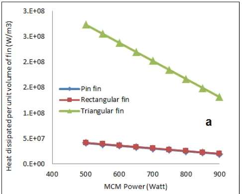
4.1. Effect of MCM Power on Heat Dissipation Per Unit Volume
Figures 3 shows the effects of heat dissipation per unit volume for three different geometries (pin fin, triangular and rectangular spine fins), and for four different material of constructions: Aluminium (Al), Copper (Cu), Beryllium (Be) and Zinc (Zn) respectively. The results showed that triangular spine fin geometry has higher heat dissipation per unit volume compared to the pin fin and rectangular spine fin geometries. The trend in Figure 3 shows that as the MCM power increases, heat dissipation per unit volume decreases this is due to the build-up in temperature thereby reducing the rate of heat dissipation.
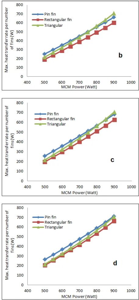
4.2. Effect of MCM Power on Maximum Heat Loss Per Number of Fins
Maximum heat loss per number of fin over certain range of MCM power shows that at lower multi chips module (MCM) power, pin fin geometry has higher heat loss when compared to the triangular and rectangular fin geometries but as the MCM power increases the triangular spine fin geometry exhibited higher heat loss than the pin fin geometry (Figure 4). Rectangular spine fin geometry remains the lowest throughout the range of MCM power investigated. For instance, at an MCM power of 750W for aluminium, pin fin geometry had heat loss per number of fin of 516W while triangular spine fin and rectangular spine fin has 471W and 426W respectively. But at higher MCM power of 900W the heat loss per number of fin was 744W, 715W and 641W for triangular spine, pin and rectangular spine fin respectively (Figure 4).
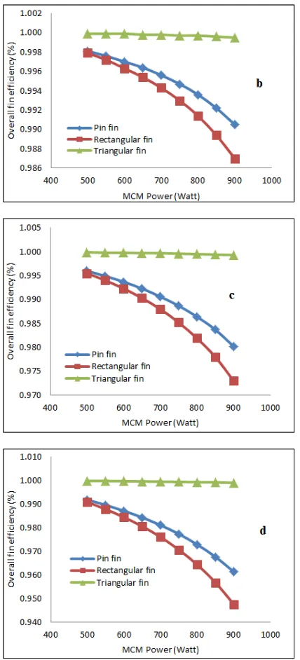
4.3. Effect of MCM Power on Overall Fin Efficiency
Figure 5 shows the overall efficiency as a function of MCM power for various fin geometries. Triangular geometry has high efficiency close to unity at low MCM power followed by the pin fin geometry and the rectangular spine fin remain the least, but as the MCM power increases the overall efficiency of the fins drops. This agrees with the phenomena that increase in the MCM power is accompanied by corresponding rise in resistance to heat dissipation.
4.4. Effect of MCM Power on Total Heat Transfer Between Fins (Bare Surfaces)
For heat dissipation in between fins or on the bare surfaces where there is no fin, Figure 6 shows that pin fin geometry has the lowest quantity of heat dissipated by the bare surface. For instance, as the MCM power increases to 900W, triangular fin has the lowest heat dissipation. The analysis shows that at lower MCM power the fins in pin fin geometry dissipate more heat than the bare surface but at higher MCM power the fins in triangular fin geometry dissipate more heat than the bare surface. In all the cases, rectangular fin geometry has the highest quantity of dissipated by the bare
Figure 5. Effect of Varying MCM Power on the Overall Fins Efficiency for Different Material (a) Cupper (b) Aluminium (c) Beryllium (d) Zinc.
Figure 6. Effect of MCM Power on the Total Transfer Between the Bare Surfaces of the Heatsink for Different Materials (a) Cupper (b) Aluminium (c) Beryllium (d) Zinc.
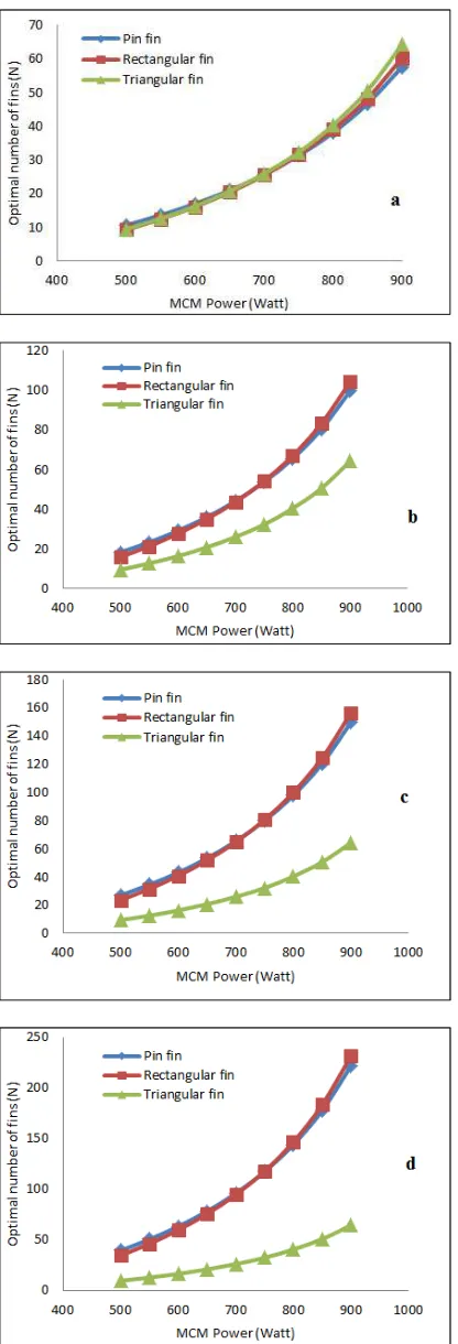
4.5. Effect of MCM Power on Optimum Number of Fins
Figure 7. Effect of MCM Power on Optimum Number of Fins for Different Material (a) Cupper (b) Aluminium (c) Beryllium (d) Zinc..
5. Conclusion
The effect of fin geometry on cooling process of computer
micro-chip was model using Matlab programming language in this study. Different fin geometries (pin fin, rectangular fin and triangular fin) were compared from the point view of heat transfer per unit volume, maximum heat loss per number fins, overall fin efficiencies, heat dissipation by the bare surface of the heatsink and optimum number of fins to effect heat dissipation. Five different materials of construction (i.e. Copper, Silver, Aluminium, Zinc, and Beryllium) were studied. Copper as material of construction of the heatsink performed better due to its high thermal conductivity. Triangular fin geometry gave the best geometry to be used for heatsink design since computer microchips operate at around 800 MCM power. The second geometry that gave a good result is the pin fin geometry while rectangular fin geometry is the least effective among the three geometries considered. The study shows that optimum number of fins needed for heatsink design, triangular fin geometry gives the lowest number compared to pin and rectangular fin geometries. Therefore, triangular fin geometry will give small size heatsink this is necessary because space management is very important in designing computer.
Nomenclature
L = Length of fin D =Diameter
k = Thermal conductivity of the material used, W/m.K
h= heat transfer coefficient, W/m.K
Ac = Cross sectional area, m2 As= Surface area, m2 P = Fin perimeter, m
Tb = Surface temperature, K T∞= Fluid stream temperature, K
w = Fin width, m
ma = mass flow rate, kg/s
t = Fin thickness, m
θ(x) = Excess temperature, K
θ(L) = Excess temperature at the tip, K
N = Number of fins
Nr=Number of fins in the horizontal row S = Fin pitch, m
qt= Total heat transfer, W qf= Heat transfer by fin, W
qb = Heat transfer at the fin base, W qmax= Maximum possible heat transfer
At = Total surface area i.e. both fin and exposed portion of
the base, m2
Af= Fin surface area, m2
Ab = Prime surface area (exposed portion of the base), m2 o
η = Overall efficiency
References
[2] Kenan, Y., Nihal, A., Isak, K, and Cafer, C. (2006) “Experimental investigation of thermal resistance of a heat sink with hexagonal fins” Applied Thermal Engineering, vol 26, pp 2262-2271.
[3] Tuckerman, D. B. and Pease, R. F. W., High-performance heat sinking for VLSI, IEEE Electron Device Letters, 1981 [4] Intel, 2007. Intel® Celeron® Processor 200∆ Sequence:
Thermal and mechanical design guidelines, October, 2007. http://www.intel.com/assets/pdf/designguide/318548.pdf (Accessed December, 2015).
[5] Chassis Plan Ltd. Cooling and noise in industrial and military computer systems http://www.chassis-plans.com/whitepapers/cooling-and-noise/ (Accessed December, 2015).
[6] Intel, 2010. Intel® Atom™ Processor N450, D410 and D510 for Embedded Applications: Thermal design guide February 2010.
http://www.intel.co.uk/content/dam/www/public/us/en/docum ents/design-guides/atom-n450-n410-d510-thermal-guide.pdf (Accessed December, 2015).
[7] Xiaolong, Z., Yi F., Johan, Teng, W, and Zhaonium, C. (2007) “A Study of CFD Simulation for On-Chip Cooling with “D CNT Micro Fin Array” IEEE 1-4244-1253-6.
[8] Khan WA, Culham RJ, Yovanovich MM. Analytical model for convection heat transfer from tube banks. J Thermophys Heat Transfer 2006; 20: 720-7.
[9] Czylwik, A. Matlab for Communications, http://nts.uni-
duisburg-essen.de/downloads/matlab/MatlabSeminar_main.pdf (accessed on 05/2016).
[10] Rajput, R. K. (2008). “Heat and Mass Transfer” S. Chand & Company Ltd. Pp 205-245 Ram Nagar, New Delhi.
[11] Incropera, P. F (1996). “Fundamentals of heat and mass transfer” John Wiley & Sons Inc. Pp 110- 127, 377-383. New York.
[12] Mills, F. A (1997). “Heat and Mass Transfer”. IRWIN Publishers Pp 80-101. Chicago.
[13] Robert H. P; Green, W.D. “Chemical Engineer’s Handbook” seventh edition, McGraw-Hill company.

![Figure 2. Triangular Fin and Triangular Spine Fin (Conical Fin) [11].](https://thumb-us.123doks.com/thumbv2/123dok_us/8571163.1716696/3.595.309.549.416.569/figure-triangular-fin-triangular-spine-fin-conical-fin.webp)