UDC: 004.92:616-001.5
Ultrasound Velocity Measurements on Healing Bones Using the External
Fixation Pins: A Two-Dimensional Simulation Study
M. G. Vavva1, V. C. Protopappas2, D. I. Fotiadis2*, K. N. Malizos3,4
1 Dept. of Material Science and Engineering, University of Ioannina, Greece
2 Dept. of Computer Science, Unit of Medical Technology and Intelligent Information Systems
University of Ioannina, Greece. [email protected]
3 Institute of Biomedical Research and Technology, Center for Research Technology-Thessaly,
Larissa, Greece
4 Dept. of Orthopaedics, Medical School, University of Thessaly, Greece
*Corresponding author
Abstract
Quantitative ultrasound has been largely used for the evaluation of fracture healing in long bones. The propagation velocity across the fracture has been proved to be a quantitative indicator of healing. In this work, we perform a feasibility study of an alternative ultrasonic configuration in which two of the pins of an already applied external fixation device are used as a means of ultrasound transmission and reception. To test and evaluate the applicability of the technique in monitoring the fracture healing course, velocity measurements are performed on two-dimensional (2D) models of intact and healing bones. Comparisons are then made with the traditional percutaneous application and a newer one, the so-called transosseous application.
The effect of a non-perpendicular pin insertion on the velocity is finally investigated by assuming various combinations of pin inclination angles. It was found that measurements of the ultrasound velocity through the pins result in higher values due to the fact that the waves travel also along the metal pins whose bulk velocity is higher that of the bone. However, the velocity was increased during healing and this trend was unaffected by any pin inclination angle. In conclusion, the proposed method can offer practical advantages in-vivo but also suffers from highly attenuated received signals. Therefore, clinical trials are needed before it is proposed for clinical use.
Keywords: 2D bone models, bone fracture, fracture fixation pins, ultrasound simulations
1. Introduction
the fracture characteristics and the magnitude of tissue damage. Bone fracture healing is a complex regenerative process including the formation and gradual consolidation of the fracture callus tissue. Progressive differentiation and ossification of the callus tissue are fundamental processes of the healing course which occur until the bone regains its initial biomechanical function, structural integrity and geometry. The need for early detection of possible complications during healing and for accurate assessment of the endpoint of the process, necessitate the development of quantitative techniques for monitoring bone healing.
Quantitative ultrasound is considered as a significant tool for the evaluation of bone properties and has been largely used for the assessment of osteoporosis and to a lesser extent for the monitoring of the fracture healing process. The axial transmission technique is the most suitable approach for the examination of long bones such as tibia and radius. Typically a transmitter and a receiver are placed along the bone axis on each side of the fracture site. In most applications the transducers are placed on skin (i.e. percutaneously). The ultrasonic waves propagate along the bone axis and their velocity is determined by the transit time of the first arriving signal (FAS) to the receiver. Animal (Abendschein et al. 1972) and clinical studies (Cunningham et al., 1990, Gerlanc et al. 1975) using the percutaneous transducer configuration have demonstrated that the gradual changes in the callus’ structural and mechanical properties lead to an increase of the propagation velocity and when bony union is achieved, the velocity of the FAS exceeds 80% that of the contralateral intact bone (Protopappas et al. 2008). In a recent animal study we introduced a transosseous application in which the transducers are implanted into the fracture region and placed directly on to the bone surface (Protopappas et al. 2005). The FAS velocity was again found to increase during the healing process.
The recent introduction of computer simulations in the ultrasonic characterization of bone has further extended our understanding about the parameters that affect ultrasound velocity measurements (Kauffman et al. 2008, Moilanen et al. 2008). Initial computer simulations investigated the relationship between the FAS velocity and the thickness of the bone cortex aiming at the diagnosis of osteoporosis (Bossy et al. 2002, Bossy et al. 2004a, Nicholson et al. 2002) by modeling the bone as a 2D plate. It has been demonstrated that when the plate thickness is larger than the wavelength in bone the FAS wave corresponds to a lateral wave propagating along the subsurface of the medium at the bulk longitudinal velocity. In the context of bone healing, computational simulations on free 2D and 3D models of healing bone showed that the ultrasound velocity increases throughout the healing process (Protopappas et al. 2006, 2007; Vavva et al. 2008). Furthermore, transosseous measurements on extended 2D models (in terms of more realistic boundary conditions) made clear that the presence of the overlying soft tissues slightly affects the velocity variation during healing (Vavva et al. 2008). Two recent studies on 2D models showed that for small fracture gaps the amplitude of the FAS is sensitive to the mechanical changes which occur at the initial stage of the healing course, suggesting that it could also be used for monitoring purposes (Dodd et al. 2006, 2008). Additional simulations on oblique fractures also revealed that the amplitude as well the transit time of the FAS are influenced by type of fracture (Dodd et al. 2008).
thickness of the overlying soft tissues along the scanning region is constant. Another important issue is that the multiple measurements that are required influence the accuracy and repeatability of the velocity calculations. According to (Bossy et al. 2004a) it is of paramount importance the transducers to be placed on the skin at a specific/constant angle; even small deviations from that angle would introduce precision errors up to 10%. Although the transosseous application addresses the problems caused by the presence of the soft tissue layers, its applicability is limited to specific fracture cases due to the semi-invasive process of transducers’ implantation (Malizos et al. 2006).
In this work we propose an alternative method of ultrasound velocity measurements by assuming the transducers to be mounted on the pins of an already applied external fixation device and we investigate whether it can provide an improved approach for monitoring bone healing. The objectives of our work are to introduce a new technique which can offer several advantages in-vivo compared to the previously described methods and evaluate its effectiveness by performing 2D simulations of ultrasound propagation. The method is first evaluated on intact bone models. Then, more realistic conditions are addressed by incorporating the callus tissue into the models. Finally, we investigate the impact of a possible non-perpendicular pin insertion by examining five additional cases which correspond to combinations of angles. The percutaneous and transosseous applications are also simulated for comparison purposes.
2. Materials and methods
2.1 Bone model
A simplified 2D model of a midshaft segment of a long bone was constructed. The bone cortices were represented by two linear elastic isotropic plates with Young's modulus,
14 bone
E = GPa, Poisson's ratio, vbone=0.37and density, ρ =1500kg m/ 3which are typical
values for bone (Protopappas et al. 2005, Bossy et al. 2004b, Nicholson et al. 2002, Protopappas et al. 2006). The plates’ thickness was 5 mm which is within the range of cortical values found in some types of human long bones (Bossy et al. 2004b, Nicholson et al. 2002, Protopappas et al. 2006). The resulting bulk longitudinal and shear velocities of the bone were 4063 m/s and 1846 m/s, respectively, which are also commonly used in literature (Njeh et al. 1998, Protopappas et al. 2007, Bossy et al. 2004b, Protopappas et al. 2006). The marrow cavity was modeled by a 10 mm fluid layer which occupied the internal gap between the two cortices. The properties of the fluid were Young’s modulus,Ebone =2GPa, Poisson’s ratio,
0.49978 bone
80 mm 35 mm
5 mm
5 mm 10 mm 3 mm
3 mm
5 mm
67 mm
Soft tissue Cortical Bone
Bone Marrow
Soft tissue Cortical Bone Pin of External Fixation Receiver
Transmitter
I II III IV
V VI
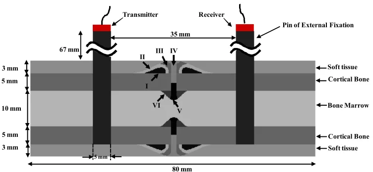
Fig. 1. The 2D model of a healing bone in which the external fixation pins and the transmitter-receiver are also shown. The capital Latin numbers correspond to the ossification regions which
comprise the callus tissue.
2.2 Model of the callus tissue
The fracture callus tissue was modeled as an inhomogeneous material consisting of six distinct ossification regions, denoted as I, II,…, VI (Fig. 1) (Protopappas et al. 2006). The geometry of the callus is described by an endosteal and a periosteal region outside and inside the borders of the plate. To represent the process of the progressive differentiation of the callus tissue in the secondary type of fracture healing, we assume the following soft tissue types to be involved in the process: initial connective tissue (ICT), soft callus (SOC), intermediate stiffness callus (MSC), stiff callus (SC) and ossified tissue (OT). We assume that healing progresses in three stages. At Stage1, the callus contains regions of MSC along the endosteal and periosteal surfaces of cortex at some distance from the fracture gap (i.e. in regions I and VI), SOC adjacent to them (regions II and V), while the remainder is occupied by ICT (regions III and IV). At Stage2, the callus consists of ICT (in region IV), SOC (in region III), MSC (in region II) and SC (in regions I, V and VI). Finally at Stage3, bone formation is almost completed and thus the callus tissue consists of OT except for two regions filled with SC (region III) and SOC (region IV). All the soft tissue types are assumed isotropic and their material properties can be found in (Protopappas et al. 2007).
2.3 Model of the external fixation pins
Two stainless steel pins of an external fixation with densityρ=7910kg/m3 and bulk
longitudinal velocity 5740 m/s were also modeled and were incorporated in the bone model. The height and the width of the pins were 90 mm and 5 mm respectively. The pins were inserted into the first three layers of the bone model and their center-to center distance was 40 mm. In the case of the healing bone models the pins were placed equidistant from the fracture callus. The frame of the external fixation device is neglected on purpose since in this study we assume that wave propagation occurs only through the external fixation pins.
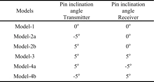
of the external fixation device perpendicularly but rather at small inclinations. All the examined combinations of pin inclination angles are presented in Table 1.In the first two models (Model-2a and 2b) the left pin was assumed to incline -5o and +5o respectively, whereas the right one
was perpendicularly inserted. In the next model (Model-3) both of the pins were assumed to deviate +5o from the perpendicular position. In the final two models both pins were inclined at
opposite angles, i.e. by +5o the left pin, by -5o the right one and vice versa in Model-4b. The
symmetrical cases are not included in the present study.
+5o
+5o +5o +5o
Fig. 2. The six combinations of ±5o angles of pin inclination.
Concerning the healing bone model, only two of the aforementioned cases were investigated i.e., the healing bone Model-2a and Model-4a.
Models Pin inclination angle Transmitter
Pin inclination angle Receiver
Model-1 0o 0o
Model-2a -5o 0o
Model-2b 5o 0o
Model-3 5o 5o
Model-4a 5o -5o
Model-4b -5o 5o
Table 1. The models that correspond to all possible combinations of the pin inclination angles.
2.4 Transmitter-Receiver Configuration
respectively. The latter simulates the implantation of the transducers directly onto the bone surface. The contact area of each transducer is 5 mm and their center-to-center distance is 40 mm, which is typically used in ultrasonic applications to the bone. Concerning the percutaneous transmitter-receiver application on the intact bone, measurements were also taken by progressively shifting the receiver by 1 mm steps with the center-to-center distance from the transmitter increasing from 40 - 50 mm.
When the pins of the external fixation devices were incorporated in the bone model, the transmitter was attached to the extracorporeal tip of the first pin and the receiver to the tip of the second pin.
In all the examined cases, the excitation signal was described by a broadband pulse consisting of a 3-cycle Gaussian-modulated 1 MHz sine (duration 3 μs). The transducers operated in the longitudinal mode.
2.5 Boundary Conditions
Infinite boundary conditions were applied to the ends of the intact and healing bone models to eliminate most of the waves that are reflected back.
The numerical solution of the 2-D wave propagation problem is performed using the finite difference method based on the commercial software Wave2000 Pro (CyberLogic, Inc., NY, USA). The element size is set to 0.1 mm, which corresponds to at least ten elements per smallest wavelength (i.e. 1.5 mm). The sampling frequency is 34.3 MHz. The duration of the recorded signals is 100 μs.
2.6 Determination of the ultrasonic wave propagation path and velocity
Typically the propagation velocity is calculated by dividing the propagation path by the measured arrival time of the FAS at the receiver. The propagation path of the FAS wave corresponds to the path that leads to the minimum propagation time and depends on the transducers’ configuration. When the transducers are placed in contact with the bone’s surface (i.e. transosseous application) the propagation path is the axial distance between the transducers.
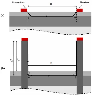
For the percutaneous application the propagation path is depicted in Fig. 3 (a) (Lowet et al., 1996). The FAS wave enters the soft tissues (i.e. the blood loaded layer) at a certain angle θ,
travels along the subsurface of the bone’s cortex in the axial direction and finally it is reradiated in the soft tissue layer to reach the receiver at the angle θ. The transit time of the FAS can be theoretically calculated as
2
FAS soft bone
t = ⋅t +t (1)
where tsoft and tbone are the propagation times along the soft tissues and the bone respectively. If
the bulk longitudinal velocity through the soft tissues is denoted ascsoftand through the bone
ascbone then eq. (1) becomes:
2 tan
1 2
cos
soft soft
FAS
soft bone
S D S
t
c c
θ θ
− ⋅ ⋅
= ⋅ ⋅ + (2)
angle between the vertical and the FAS wave path. Differentiating eq. (2) to θ leads to the minimum arrival time,tFAS when
sin soft bone c c
θ = (3)
For the given values of csoft andcbone, θequals to 22.9o. By substituting the derived angle value
in eq. (2) the tFAS equals to 12.11 μs.
For the models in which the external fixation pins are perpendicularly inserted, we first formulate an initial hypothesis based on the above analysis and we investigate whether this assumption indeed leads to the shortest wave path. According to this hypothesis, the FAS propagates along the pin axis, enters the soft tissues at the angle θ, as shown in Fig. 3 (b) by the dotted lines, travels along the subsurface of the cortical layer, leaves the bone and enters the pins at the same angle to reach the receiver. The FAS arrival time at the receiver is then calculated according to eq. (1) as:
2 2
FAS pins soft bone
t = ⋅t + ⋅t +t (4)
where tpins is the propagation time along the pins. Eq. (2) then becomes:
2 tan
1
2 2
cos
pin soft soft
FAS
pin soft bone
S S D S
t
c c c
θ θ
− ⋅ ⋅
= ⋅ + ⋅ ⋅ + (5)
wherecpin is the bulk longitudinal velocity through the pins and Spin is the height of the pin’s extracorporeal part equal to 67 mm. For the given values of θand cpin ,tFAS equals to 3.55μs.
Nevertheless, it was found that this result does not correspond to the shortest propagation path. In fact, the FAS wave travels along the pin, then propagates along the bone subsurface without having been radiated into the soft tissues, and finally enters the second pin to reach the receiver, depicted in Fig. 3 (b) with the dashed line. Under this assumption the transit time of the FAS wave is now given as
2
FAS pin bone
t = ⋅t +t (6)
which can be also written as:
2 pin FAS pin bone S D t c c ′
= ⋅ + (7)
where Spin′ =70mm i.e. the length of the extracorporeal part of the pin (i.e. 67 mm) plus the
length of the part within the soft tissue layer (i.e. 3 mm). Substituting the values ofcpin,cbone,Dand Spin′ in eq. (7) it is derived that tFAS =3.3μs i.e., smaller than the value
resulted from eq. (5).
To investigate whether this is also the case when the inserted pins are assumed inclined by 5o, we just calculate the FAS transit time from the interface between the pin and the soft tissues
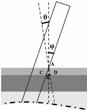
enters the soft tissues at the critical angle θ depicted in Fig. 4. The second one corresponds to the direct path from the point A to the point C (i.e. cross point the interface between the pin and the bone cortex) and then to the point D. This path is followed when the FAS enters the bone without having been radiated into the soft tissues.
Fig. 3. The propagation path (a) in the percutaneous application and (b) in the case of a perpendicular pin isertion (dashed lines). The dotted lines depict the initial path assumption in
which the FAS is radiated into the soft tissues before entering and after leaving the bone.
Τhe propagation path A-D corresponds to a FAS arrival time, tADgiven by:
cos soft AD
soft
S t
c θ
=
⋅ (8)
whereas the propagation path A-C-B-D to the arrival time tACBDgiven by:
tan 1
cos soft soft ACBD
BD
pin bone
S S
t S
c c
φ φ
⋅
= ⋅ + + (9)
whereφis the inclination angle equal to 5o and
BD
S which is found by assuming the critical angle θ. For the given values of the quantities it is derived from eqs. (8) and (9) that
(a)
1.9 AD
t = μs and tACBD =0.66 μs which shows that the FAS wave propagates through the
A-C-B-D path.
In the case of +5o inclination angle is it is obvious that the FAS wave propagates from the
pins to the bone and vice-versa according to the previous assumption.
Fig. 4. The assumptions made for the path that the FAS follows when traveling from the pins into the bone in the case of +5o inclination angle.
From the above comparative analysis, it is deduced that regardless of the pin inclination angle, in all the examined cases, the FAS wave propagates along the pins and along the surface of the bone without being radiated into the soft tissues. The theoretically determined shortest propagation paths from transmitter to receiver in all the examined cases are shown in Table 2.
Models Theoretical path (mm)
Model-1 175
Model-2a 175.5
Model-2b 176.6
Model-3 177.2
Model-4a 178.2
Model-4b 176.1
Table 2. The theoretical propagation path calculated for all the examined models.
zero-crossings, signal extrema, etc., which are affected by frequency-dependent attenuation, mode interference, etc. (Bossy et al. 2002, Nicholson 2002, Protopappas et al. 2005).
3. Results
For the percutaneous application two different propagation velocities were derived. First, the velocity was calculated as the ratio of the propagation path to the measured FAS arrival time. This velocity was found 3001 m/s, whereas the theoretically calculated value was 3137 m/s. However, these values are significantly smaller than that of the bone and constitute only an apparent value due to the fact that the FAS traveled both within the bone and the soft tissues. To evaluate our results, measurements were then obtained by progressively shifting the receiver away from the transmitter. The velocity which is determined by applying linear regression analysis on measurements and calculating the slope of the linear regression line that relates the transducers’ distance to the FAS arrival time, yields the bone velocity since any delay within the soft tissues becomes an offset. The velocity was found equal to 3915 m/s (determination coefficientR2 =0.98) for the intact bone, which is close to the nominal bulk longitudinal velocity of bone (4063 m/s).
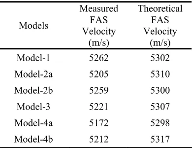
Since placing the receiver at multiple recording regions is not applicable when the pins of the external fixation device are inserted in the intact bone models, an apparent velocity can only be obtained for this configuration. In Table 3 we present the measured FAS velocity for all the combinations of pin inclination calculated as the ratio of the path to the FAS arrival time as detected at the simulated signals from the bone models. The theoretical FAS velocities which correspond to the theoretically derived FAS arrival times at the receiver are also presented comparison purposes. The theoretical propagation paths shown Table 2 were used for all the velocity calculations.
Models
Measured FAS Velocity
(m/s)
Theoretical FAS Velocity
(m/s)
Model-1 5262 5302 Model-2a 5205 5310 Model-2b 5259 5300 Model-3 5221 5307 Model-4a 5172 5298 Model-4b 5212 5317
Table 3. Theoretical and measured velocity values for all the examined models.
velocity is lower than the theoretical one by 105 m/s (2% difference), for Model-3 by 86 m/s (1.7% difference) and for Model-2b by 41 m/s (0.8% difference).
It is also shown that the theoretically derived velocity is not significantly affected by the pin inclination (maximum difference 0.28% for Model-4b). Similar observations can be also made for the measured velocity values in Models-2b, 3 and 4b. However, the effect was slightly greater for the velocities measured on the bone Models-2a and 4a which are lower than the baseline measurement on Model-1 by 1.1% and 1.8% respectively.
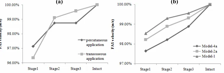
Concerning the healing bone models the FAS velocity measured at each healing stage for all the examined cases is shown in Fig. 6. The FAS propagation path was assumed identical to that
Fig. 6. Velocity variation over the healing stages (a) for the percutaneous and transosseous applications and (b) for the models containing the external fixation pins.
in the corresponding intact models, being unaffected by the geometry and the properties of the callus region. Measurements were first obtained from the healing bone without the pins and with the transducers being placed either percutaneously or transosseously (Fig. 6(a)). In both cases the FAS velocity at Stage1 is lower than that of the intact bone and gradually increases towards Stage3. At Stage3 the velocity is very close to the intact bone. Similar velocity trends are also observed when the external fixation pins are incorporated in the models (i.e., Models-1, 2a and 4a) (Fig.6 (b)). However, when the pins were assumed inclined (Models-2a and 4a), the velocity values during healing were slightly lower than those obtained from Model-1. In general, only small differences are observed in the FAS velocity between Models-2a and 4a, suggesting that velocity measurements are not influenced by possible pin inclination.
4. Discussion
In this work we present a feasibility study of an alternative transmitter-receiver configuration in which the transducers are assumed to be mounted on the extracorporeal tips of an already applied external fixation device. Our main objectives were to (1) propose a new measurement technique that could address the practical limitations of the in-vivo application of existing techniques and (2) investigate the effectiveness of the method by performing velocity measurements on 2D computational models of intact and healing bones.
The main issue arising by attaching the transducers on the tips of the external fixation pins is the fact that the velocity reflects an apparent value that corresponds to an average velocity over the whole propagation path rather along the bone and the fracture. Although an apparent velocity is measured from the percutaneous application too, the effect is more pronounced for
the proposed method because the length of the pins is typically much longer than the propagation path along the bone. One of the major advantages of the proposed method is that it is not affected by the overlying soft tissue layer as opposed to the percutaneous applications. Even if the scanning method is often used in percutaneous configurations to overcome the tissue thickness effect, this cannot be useful for bone fractures because the time delay across the callus becomes then a time offset. The problem of the soft tissues becomes crucial for the percutaneous measurements when the bone is located deep (e.g. the femur). In such cases, one needs to measure the soft tissue layer below each transducers; however, the pressure applied against the skin deforms the soft tissues and the thickness changes according to the pressure level. On the other hand, the proposed method does not require measuring the soft tissue thickness, since for small inclination angles, the FAS wave was found to enter and leave the bone without having been radiated into the soft tissues. It should be noted that this propagation path is valid for pin inclination smaller than 25o, which angle is far wider that that encountered
in practice. Therefore, the propagation path can be accurately determined by knowing the pin length and the depth of their insertion in the bone which depth can be measured in-vivo from one post-operative X-ray.
However, the actual propagation may be also influenced by other parameters such as the irregular 3D geometry the anisotropy and porosity of the bone which are not taken into consideration in the 2D model of the bone midshaft segment that was utilized here. Our main objective was to compare between the proposed configuration and those commonly used ultrasonic configurations rather than provide an accurate model of a long bone. Furthermore, as demonstrated in a 3D study in which the transducers were placed on the bone surface (Protopappas et al. 2007), the FAS wave is not influenced by the convex curvature and therefore no significant differences in velocity measurements are expected between 2D and 3D simulations. Anisotropy was also found not to affect the FAS velocity, provided that the elastic constant in the axial direction (C33) is the same for isotropy and anisotropy (Protopappas et al. 2007, Bossy et al. 2004b). The model of the callus tissue was realistic since it was assumed as an inhomogeneous material consisting of several ossification regions with gradually evolving material properties during the simulated 3-stage fracture healing (Protopappas et al. 2007). The healing stages corresponded to critical phases of the healing course.
The proposed method was initially evaluated on intact bone models. Although such an assumption is unrealistic, it allows for velocity measurements through the pins that are not influenced by the geometrical and material properties of the callus tissue. The results indicated a significant increase in the velocity values compared to percutaneous and transosseous applications. This can be attributed to the fact that the FAS wave propagates along the stainless steel pins whose bulk longitudinal velocity (i.e., 5740 m/s) is higher than that of the bone (i.e., 4063 m/s).
insertion of the pins into the models gives raise to complicated wave guidance phenomena which cannot be effectively evaluated.
The inclinations of the external fixation pins had generally no significant impact on the FAS velocity in both the intact and the healing bones. The velocity was found to be mostly but rather insignificantly affected when the first and the second pins were inclined at +5o and -5o
respectively (Model-4a), which was actually expected since such combination of pin inclination angles corresponded to the longest propagation path. Nevertheless, even if the velocity was dependent on the pin inclination angle, we are interested in the changes of the FAS velocity from Stage1 to Stage3 rather than the absolute velocity values. However, the proposed method is quite insensitive to the alterations which occur in the callus during healing due to the increased time delay of the FAS into the pins.
A further limitation of the method is the high attenuation in the received signals induced by multiple reflections at the pin-bone interfaces, the low acoustical coupling between the bone and the pin, and the fact that most of the energy is transmitted perpendicularly to the bone axis rendering the axial transmission of the FAS more difficult than in transosseous or percutaneous applications.
Overall, the proposed method combines the advantageous features of each of the existing techniques since (1) it is non-invasive, as opposed to the transosseous applications and (2) the measurements are not affected by the overlying soft tissue, which is a significant limitation of the percutaneous applications especially at skeletal sites where the overlying soft tissues are thick, such as at the femur. Furthermore, the rigid attachment of the transducers on the tips of the pins increases the repeatability of the method since it does not require manual transducer re-positioning each time a measurement is to be performed, as occurs for the percutaneous application. Nevertheless, the results obtained from the present computational study need to be interpreted in conjunction with clinical measurements so as to be validated.
4. Conclusions
In this work we proposed a new technique for velocity measurements and we investigated whether it could provide an enhanced approach in monitoring the fracture healing process. For the first time the pins of an already applied external fixation device are proposed to serve as a means of ultrasound transmission and reception during the fracture healing process. The velocity was found to increase during the healing stages as in the percutaneous or transosseous applications. However, only apparent velocity values can be derived from the proposed method corresponding to the whole propagation path (i.e. pins, bone and fracture) rather than to the fracture zone. This justifies the increased velocity values which were found in all the examined cases. In this respect, the sensitivity of the method becomes limited and thus renders the assessment of small changes in the callus during the healing course more difficult compared to the existing methods. It was also shown that small inclination angles of the pins had no significant impact on the results suggesting that the method could provide accurate results when applied in-vivo. Although the proposed technique can offer several advantages in-vivo
Acknowledgements
This work is part funded by the General Secretariat of Research and Development, Hellenic Ministry of the Development (“PENED 2003” 03ED140).
References
Abendschein, W. F. and Hyatt, G. W. (1972), Ultrasonics and physical properties of healing bone. J Trauma, Vol. 12, No. 4, pp. 297-301.
Bossy, E., Talmant, M., and Laugier, P. (2002). Effect of bone cortical thickness on velocity measurements using ultrasonic axial transmission: a 2D simulation study. J Acoust SocAm, 112 (1), 297-307.
Bossy E., Talmant M., Defontaine M., Patat N., and Laugier P. (2004a). Bidirectional axial transmission can improve accuracy and precision of ultrasonic velocity measurement in cortical bone: A validation on test materials, IEEE Trans. Ultrason. Ferroelectr. Freq. Control 51(1), 71–79.
Bossy E., Talmant M. and Laugier P., (2004b). Three-dimensional simulations of ultrasonic axial transmission velocity measurement on cortical bone models, J. Acoust. Soc. Am. 115(5). 2314–2324.
Camus, E., Talmant, M., Berger, G., and Laugier, P. (2000). Analysis of the axial transmission technique for the assessment of skeletal status, J. Acoust. Soc. Am. 108(6), 3058–3065. Cunningham, J. L., Kenwright, J. and Kershaw, C. J. (1990). Biomechanical measurement of
fracture healing, J. Med. Eng Technol., 14 (3), 92-101.
Dodd S.P., Cummingham J.L., Miles A.W., Gheduzzi S., Humphrey V.F. (2006). Ultrasonic propagation in cortical bone mimics, Phys. Med. Biol. 51(18) 4635-4647.
Dodd, S., Cunningham J., Miles A., Gheduzzi S., Humphrey V. (2008). Ultrasound Transmission Loss Across Transverse and Oblique Bone Fractures: An In Vitro Study,
Ultras. Med. Biol., 34 (3), 454 – 462.
Gerlanc M, Haddad D, Hyatt, G. W., Langloh JT, and Hilaire P. S. (1975). Ultrasonic study of normal and fractured bone, Clin Orthop Relat Res., 111, 175-180.
Kauffman J. J. (2008). Ultrasonic Guided Waves in Bone, IEEE Trans. Ultr. Ferroel. Freq. Cont. 55(6), 1205-1218.
Lee K.I., Yoon S.W. (2004). Feasibility of bone assessment with leaky Lamb waves in bone phantoms and a bovine tibia, J. Acoust. Soc. Am., 115(6), 3210-3217.
Lowet, G., and Van Der Perre, G. (1996). Ultrasound velocity measurements in long bones: measurement method and simulation of ultrasound wave propagation, J. Biomech., 29(10), 1255–1262.
Malizos K.N., Papachristos A.A., Protopappas V.C., Fotiadis D.I. (2006). Transosseous Application of Low-Intensity Ultrasound for the Enhancement and Monitoring of Fracture Healing Process in a Sheep Osteotomy Model, Bone, 38(4), 530-539.
Maylia, E., and Nokes, L. D. (1999). The use of ultrasonics in orthpaedics—a review, Technol. Health Care 7, 1–28.
Moilanen P. (2008). Ultrasonic Guided Waves in Bone, IEEE Trans. Ultr. Ferroel. Freq. Cont.
55(6), 1277-1286.
Nicholson, P. H., Moilanen, P., Karkkainen, T., Timonen, J., and Cheng, S. (2002). Guided ultrasonic waves in long bones: modelling, experiment and in vivo application, Physiol Meas., 23(4), 755-768.
Njeh, C. F., Kearton, J. R., Hans, D., and Boivin, C. M. (1998). The use of quantitative ultrasound to monitor fracture healing: a feasibility study using phantoms, Med. Eng. Phys.,
Njeh, C., Hans, D., Wu, C., Kantorovich, E., Sister, M., Fuerst, T., and Genant, H. (1999). An in vitro investigation of the dependence on sample thickness of the speed of sound along the specimen, Med. Eng. Phys. 21, 651–659.
Protopappas, V. C., Baga, D. A., Fotiadis, D. I., Likas, A. C., Papachristos, A. A., and Malizos, K. N. (2005). An ultrasound wearable system for the monitoring and acceleration of fracture healing in long bones, IEEE Trans. Biomed Eng, 52(9), 1597-1608.
Protopappas, V. C., Fotiadis, D. I., and Malizos, K. N. (2006). Guided ultrasound wave propagation in intact and healing long bones, Ultrasound Med. Biol. 32(5), 693–708. Protopappas V.C., Kourtis I.C., Kourtis L.C., Malizos K.N., Massalas C.V., Fotiadis D.I.,
(2007). Three-dimensional finite element modeling of guided wave ultrasound wave propagation in intact and healing long bones. J. Acoust. Soc. Am. 121(6) 3907-3921. Protopappas, V. C., Vavva, M. G., Fotiadis, D. I., and Malizos, K. N. (2008). Ultrasonic
monitoring of bone fracture healing, IEEE Trans. Ultr. Ferroel. Freq. Cont. 55(6), 1243-1255.
Raum, K., Leguerney, I., Chandelier, F., Bossy, E., Talmant, M., Saïed, A., Peyrin, F., and Laugier, P. (2005). Bone microstructure and elastic tissue properties are reflected in QUS axial transmission measurements, Ultrasound Med. Biol. 31(9), 1225–1235.
Saulgozis, J., Pontaga, L., and Van Der Perre, G. (1996). The effect of fracture and fracture fixation on ultrasonic velocity and attenuation,Physiol. Meas 17(3), 201–211.
Tatarinov, A., Sarvazyan, N., and Sarvazyan, A. (2005). Use of multiple acoustic wave modes for assessment of long bones: Model study, Ultrasonics 43, 672–680.