(UDC: 612.766)
Bioengineering and tire design related research at LIPS laboratory
– a summary of results
N. Korunović1, M. Stojković1, J. Milovanović1, N. Vitković1, M. Trifunović1, M. Manić1,
M. Trajanović1*
1 Faculty of Mechanical Engineering, University of Niš, Aleksandra Medvedeva 14, 18000 Niš,
Serbia
e-mail: [email protected]
*corresponding author
Abstract
Results of representative projects, in which the research team of LIPS laboratory participated, are presented here in summary. A new methodology for bone geometry modeling was developed, which implies recognition of bone oriented geometrical features on freeform geometry. It enables faster and easier creation of geometrical models based on minimal data obtained by noninvasive methods. Stress analysis of bones with traumas and implants was performed as well as optimization of implant structure and position. Original scaffold design was developed as well as a methodology for harmonization of elastic properties of scaffold and surrounding tissue. A methodology for parametric tire modeling with application of existing engineering knowledge was defined, as well as a procedure for prediction of tire behavior during straight line rolling, braking and cornering. Original approach to automatized creation of FEM models based on dedicated CAD models was introduced, which enables fast modification of FEM models and thus simplifies structural optimization procedures.
Keywords: Biomechanics, bones, scaffold, implant, reverse engineering, freeform geometry, tire, FEM, knowledge based design
1. Introduction
Researchers from LIPS (Laboratory for Intelligent Production Systems), Faculty of Mechanical Engineering Niš, are involved in the development and application of modern CAD/CAM/CAE systems, in context of high-complexity products and systems modeling. Out of many interests and research areas of LIPS personnel, bioengineering and tire design are selected for this review, as those were the topics of most representative projects in LIPS in last 10-15 years. This certainly does not exhaust the list of scientific fields and activities in which LIPS researchers actively participate.
defined, which may be used in sensitivity studies and structural optimization. Based on defined methods, stress analysis of bones with traumas and implants was performed as well as optimization of implant structure and position. Mentioned techniques were also used to develop an original design of scaffold as well as a methodology for harmonization of elastic properties of scaffold and surrounding tissue. Selected scaffold designs were also produced using additive technologies.
Tire design has been another favorite area of research for LIPS personnel. The activities started with definition of new approaches to creation of parametric tire geometry, supported by knowledge-based technologies. Original approach to automatized creation of FEM models based on dedicated CAD models was also introduced, which enables fast modification of FEM models and thus simplifies structural optimization procedures. Detailed procedures for prediction of tire behavior during straight line rolling, braking and cornering were defined, which are already used in engineering practice.
The following text is divided into two main chapters, which describe main contributions of LIPS researchers in the fields of bioengineering and tire design. Bioengineering chapter is further divided in three subchapters: the first is dedicated to bone geometry reconstruction and modeling, the second to modeling and manufacturing of implants and scaffolds and the third to stress analysis in biomechanics. Tire design chapter consists of two parts. The first is related to tire geometry modeling and manufacturing and the second to simulation of tire behavior.
2. Bioengineering
2.1 Bone geometry reconstruction and modeling
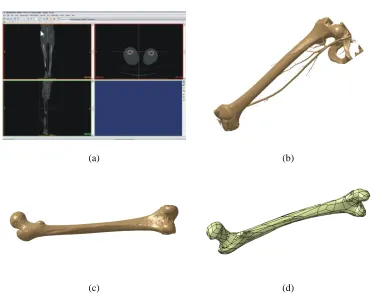
Geometrically accurate and anatomically correct 3D geometrical models of human bones or bone sections are important prerequisite for successful pre-operative planning in orthopedic surgery. 3D polygonal models of bones are usually based on Computed Tomography (CT) or Magnetic Resonance Imaging (MRI) data. Depending on the application, polygonal model may be used directly or converted to surface and solid CAD models. In either case, considerable user intervention is required using geometry reconstruction techniques such as “healing” or surface approximation, as shown by Korunović et al. (2010) and Stevanović et al. (2012). A typical process of geometry reconstruction based on CT image set is shown in Fig. 4.
(a) (b)
(c) (d)
Fig. 4. Typical process of subject specific bone geometry reconstruction. (a) Image of lower extremities obtained by CT; (b) Polygonal model of femur and parts of surrounding bones based
on “point cloud”, which is defined by abrupt radiological density changes; (c) Polygonal model of femur, with segments of surrounding bones and soft tissue removed; (d) NURBS surface
which represents the external envelope of femur (Korunović et al. 2010)
Fig. 5. Basic scheme of software system for the creation of customized bone polygonal model (Vitković et al. 2013)
Parametric model Images(s) from medical
imaging devices (e.g. CT)
Customized bone polygonal model Reading and processing
of input data
Implementation and processing of parametric
As discussed by Stojković et al. (2009), the basic prerequisite for fast and accurate reverse modeling of a human bone’s geometry is the identification of the referential geometrical entities (RGEs), that is, characteristic points, directions, planes and views (Fig. 6). All other elements of the bone’s geometry (curves, surfaces and solids) should be referenced to RGEs. The paper presents identification of RGEs in the case of specific reverse modeling approach of the geometry of femur, which starts with radiological image input.
(a) (b) (c)
Fig. 6. Identification of femoral RGEs. (a) RGEs of proximal femur – characteristic planes based on inferior margin of trochanter’s wedge and the main RGE of femoral shaft – femoral
shaft axis; (b) A-P view; (c) L–M view(Stojković et al. 2009)
Explicit definition of RGEs of femur provides significant improvement in reverse modeling and engineering of femoral geometry. In addition, using CAD and reverse modeling techniques brings new quality into the human bone morphology perception. Besides the morphometric analysis, reverse modeling and engineering provide all necessary tools for design and rapid prototyping of customized implants. Reverse modeling features help development of operational methods and operation preparation by identification of more accurate entrance and more accurate placement for different fixing devices. Moreover, reverse modeling of the human bone’s geometry is the indispensable part of the bone’s structural and kinematic analyses.
(a) (b) (c)
Fig. 7. Reverse modeling of trochanter region. (a) Identification the RGEs of the trochanter region, in particular the “TKeel” view of the femoral trochanters; (b) Mirroring the anterior side
of the trochanter canoe hull - the position of the trochanter canoe inside the proximal femur (medial aspect); (c) The trochanter wedge in the junction of the femoral shaft and neck
(Stojković et al. 2012)
The consequences of aforementioned perception of the trochanteric region could be very important to trochanter fractures treatment, operation planning and implant and endoprosthesis design and selection. In addition, from the viewpoint of anatomy, the thesis on the trochanteric canoe could appear as very usable concerning the additional biomechanical analysis of the femur as well as regarding additional elucidation of the proximal femur ossification.
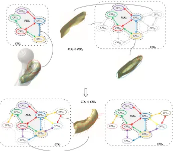
Trifunović (2016) used Active Semantic Model (ASM) as Knowledge Based Engineering (KBE) add-in for supporting process of geometric modeling or/and digital reconstruction of objects with free-form elements. The approach was tested on the example of reverse modeling of human femur geometry. The example consisted of three parts, within which procedures for reverse modeling of trochanteric region, femoral shaft and distal femur were proposed. Example was used for testing the ability of ASM to conduct semantic interpretation of geometric features of new, i.e. unknown, object during the reverse modeling process. After semantically describing the geometry of a new object, its semantic categorization is performed by the procedure for determining topologically analogous association plexuses and contexts, and finally the cognitive data processing algorithms recognize/generate applicable and relevant answers in accordance with the user’s request (which, in this case, is the method for reverse modeling of the object). The answer is being generated by conducting the context upgrading procedure (which is essentially implemented mechanism for case-based/analogy-based reasoning in ASM).
geometry. Context which subset is the exemplary association plexus, contains also association plexus used for describing the method of ship hull geometric modeling (Fig. 8, up right). Generation of the trochanteric region reverse modeling method (Fig. 8, down left) is done by upgrading input association plexus modeled on remainder of the context which subset (exemplary association plexus) is recognized as topologically analogous association plexus.
Fig. 8. Semantic interpretation for the part of the test example related to the trochanteric region (Trifunović 2016)
2.2 Geometrical modeling and manufacturing of implants and scaffolds
Reconstruction and modeling of bone geometry itself is not often the main goal of research in bioengineering. In many cases the optimal shape of medical implants or scaffolds is sought or their interaction with surrounding tissue is investigated. Geometrical models of various implants were created as part of research conducted in LIPS laboratory. Some of those were standardized and some were customized i.e. based on underlying bone geometry. Subject specific geometrical models of bone tissue matrices or scaffolds were also created, according to new design methodology. The purpose of described models was the reconstruction of missing tissue, stress analysis and structural optimization or manufacturing using additive technologies.
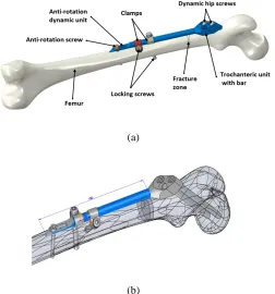
The research presented by Korunović et al. (2015b) and Trajanović et al. (2010) focused on internal fixation using selfdynamisable internal fixator (SIF) developed by Prof. Mitković, applied in subtrochanteric femoral fracture treatment. The main goal of the research was to conduct structural analysis and sensitivity analyses that would help in surgery planning, as described in the next chapter. SIF is modular and the size and shape of its modules are
CPT11 CPT73 CPT72 CPT74 CPT15 CTXX PLXX CPT11 CPT13 CPT12 CPT14 CPT15 CTXN PLXN CPT19 CPT22 CPT25 CPT33 CPT11 CPT13 CPT12 CPT14 CPT15 CTXN PLXN CPT19 CPT22 CPT25 CPT33 CPT11 CPT73 CPT72 CPT74 CPT15 CTXX PLXX CPT66 CPT63 CPT25 CPT59
PLXX©PLXN
standardized. Assembly constraints which an orthopedist may change during surgery (length of trochanteric bar, distance between clamps) were set as main design parameters inside CAD model of femur-SIF assembly (Fig. 9). The important features of presented CAD model were appropriate parameterization and flexibility. In other words, when the values of driving parameters inside the CAD model are changed, the geometry should be automatically rebuilt to reflect the desired changes, without any errors or additional user intervention.
(a)
(b)
Fig. 9. An assembly containing geometrical models of femur and SIF. (a) Assembly components; (b) Main design parameters
As the values of design parameters are changed, the position of the fixator on the bone is modified. An orthopedist does not know this position in advance, nor is he able to describe it using the accurate points and distances. In practice, anatomical landmarks like approximate points on trochanters, femur head or neck, are used to determine an initial position of the fixator. Fluoroscopy (live X-ray imaging) is applied during surgery to find its exact position. Descriptive empirical constrains are used thereby such as: “the first dynamic hip screw should pass near the center of femur head, with its tip finishing a couple of millimeters away from femur head surface, and the second should stay a couple of millimeters away from femur neck surface”. One of the most complex tasks in the research was to convert those empirical constraints to dimensional parameters and constraints within the CAD model.
scans, an indicated location for placing the implant is recognized and the design of a 3D model of customized implants is made. Employing this method it is possible to design volumetric implants used for replacing part of the bone or a plate type for fixation of a bone part (Fig. 10). The sides of the implants, lying on the bone, are fully aligned with the anatomical shape of the bone surface which neighbors the fracture. The models are designed for implants production utilizing any method and are ideal for 3D printing of implants.
Fig. 10. Different types of customized implants (Manić et al. 2015a)
Volumetric implants are created in two steps (Manić et al. 2015a). In the first step, fracture volume is created inside 3D bone model, based on CT scan and surgeon’s suggestions (Fig. 11a). After the fracture is created, bone fragments that do not belong to the implant, are removed. By removing desired bone fragments, a basic 3D model of the implant is created (Fig. 11b). The initial model of implant can further be modified using advanced techniques for free form modeling. For instance, bevels, rounding and additional screw holes can be added and everything else that is needed for implant’s production and implementation.
(a) (b)
Fig. 11. Creation of volumetric customized implant (a) 3D model of fracture; (b) Basic 3D model of volumetric implant (Manić et al. 2015a)
CUSTOMIZED IMPLANTS
3D VOLUMETRIC
IMPLANT
3D PLATE
BONE IMPLANT
SCAFFOLDS PLATES FOR CONNECTION
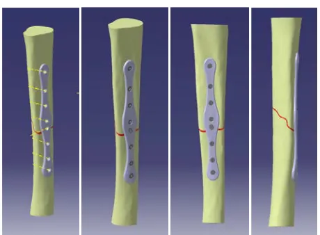
The creation of plate type customized implant (Manić et al. 2015a) is shown in Fig. 12. Close to the model of the fracture and to the lateral surface of the bone, a datum plane is created (Fig. 12a). The position and orientation of the plane is suggested by surgeon. On the plane, the contour of the proximal part of the plate is drawn. Based on the contour, extruded surface is created that penetrates the bone surface and creates the intersection curve (Fig. 12b). The part of the bone surface inside the intersection curve represents the inner surface of the customized implant (Fig. 12c). This surface is then extruded to form a full 3D model of a proximal fixation plate that is completely anatomically adjusted to the surface of the proximal part of the bone (Fig. 12c).
(a) (b) (c)
Fig. 12. Creation of plate type customized implant. (a) Contour of the proximal part of the plate; (b) Extrusion of the contour and its penetration through the bone; (c) Intersection contour
and extruded surface (Manić et al. 2015a)
Fig. 13.An assembly of internal customized fixator and broken bone parts (Manić et al. 2015a)
The developed methodology for creation of customized implants was also used in research by (Manić et al. 2015b) to create models of dynamic fixator for tibia according to Mitković (Fig. 14).
(a) (b) (c)
Fig. 14. Creation of customized dynamic fixator for tibia according to Mitković. (a) Creating the contour of the proximal part of the fixation; (b) Creating the intersecting contour curve; (c)
Final model of dynamic fixator (Manić et al. 2015b, Vitković et al. 2015)
(a) (b)
(a) (b)
Fig. 15. Sternum body reconstruction. (a) Identification of RGEs (images are captured from geometrical analysis of healthy samples); (b) Creation of sternum slices and referential points of
guiding curve in their mass-center points; (c) Remodeling virtual outer surface of the sternum body including the missing part in accordance to the geometry of healthy sternum samples, (d) Simplifying the geometry to make it moldable including definition of the mold splitting surface
(Stojković et al. 2010)
In this particular case, the redesign of the missing part of the sternum in CAD software took three designer-hours. At the same time, the suitable simplification of the geometry affected the fabrication of simpler and less expensive casting molds. Furthermore, the core of the developed algorithm for the reverse modeling of sternum can be applied in the reverse modeling improvement of other tile (or plate-like) bones.
(a) (b)
(a) (b)
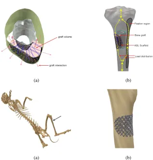
Fig. 16. Anatomically Shaped Lattice Scaffold design concept. (a) Bone graft insertion: (b) Load distribution schema; (c) (d) The case of ASLS aimed to proximal diaphyseal trauma of
rabbit tibia (Stojković et al. 2013)
(a) (b)
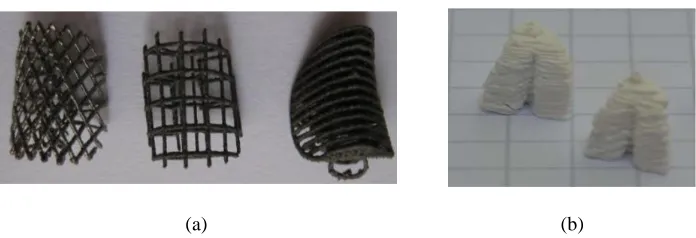
Fig. 17. Lattice scaffold concept designs fabricated using additive technologies. (a) Permanent latticed scaffolds of Ti - alloys; (b) Biodegradable scaffolds of HA
(Milovanović 2014)
2.3 Stress analysis in biomechanics
The main topic of this chapter is the application of finite element method (FEM) to stress analysis of biomechanical systems. Throughout the research performed in LIPS, stress analysis has been used to determine critical loads on human bones, implants and scaffolds and to optimize implant and scaffold design.
In order for results of stress analysis to be correct, the underlying FEM models must be valid and accurate. When FEM models of bones are considered, some significant differences exist comparing to standard engineering applications. Several aspects are very important for creation of an accurate model, and especially bone geometry reconstruction, material characterization and definition of loads and boundary conditions
General aspects of bone geometry reconstruction were already discussed in previous chapter. Accuracy of reconstructed bone geometry is also very important for stress analysis using FEM. It has been shown in practice that some of the most important sources of accuracy errors in bone geometry reconstruction are: medical image related parameters like spatial resolution or section thickness (which in case of CT are inversely proportional to radiation dose), image reconstruction algorithm, condition of patient's bone tissue and bone surface reconstruction algorithms. During reconstruction of human femur (Korunović et al. 2010, Trajanović et al. 2010) and tibia (Stevanović et al. 2012), care has been taken that models are created as accurately as possible, considering the available resolutions of CT scans.
Fig. 18. Zones created in the interior of femur model, including the zone of fracture. The zones inside spongious bone have been created in such way that they correspond to volumes of
different trabecular density (Trajanović 2010)
Fig. 19. Finite elements created inside various zones of FEM model. Equivalent moduli of elasticity assigned to each of the zones: compact bone – 17GPa, spongious bone of higher
trabecular density – 0.4 GPa, spongious bone of lower trabecular density – 0.1 GPa (Trajanović 2010)
In contrast to zoning approach, mapping approach to material characterization was used by Stevanović et al. (2012) to create a FEM model of human tibia. Preliminary stress analysis was then performed to check model integrity (Fig. 20). Similar analysis was also performed on FEM model of human femur by Trajanović et al. (2010) and also by Vulović et al. (2011) using FEM software PAK (Fig. 21).
Fig. 21.Preliminary stress analysis of human femur (Korunović et al. 2010, Vulović et al. 2011)
As discussed by Korunović et al. (2013), some of the main factors that influence the material characterization accuracy are the choice of material model, the approach to material properties averaging, x-ray tube parameters, scanner calibration, relations between CT image gray values and bone density and relations between bone density and elastic properties of the bone. The paper brings a comparison of numerical results obtained from a number of subject-specific analyses of human femur, in which the approaches to material modeling were varied. Material modeling was performed using either geometry segmentation with material properties averaging or local material mapping. A combined approach was also introduced, where the bone was divided into main zones only and inside each zone material mapping was performed. The results of the analyses (Table 1) were examined and mutually compared, and the influence of material characterization errors to analyses results was identified and explained.
Femur model Material characterization Number of elements Number of nodes Max. displacement u[mm] Max. Eq. Stress [MPa] Max. strain
1a Mapped, 20 material
definitions 59 926 98 298 5.50 20.26 0.00192
1b Mapped, 100 material
definitions 59 926 98 298 5.49 20.10 0.00202
1c Mapped, 300 material
definitions 59 926 98 298 5.49 20.26 0.00201
2 Zoned + Mapped, 100
material definitions 149 712 217 762 5.24 18.33 0.00200
3
Zoned,
Ecortical=12.7GPa,
Etrabecular=0.07-0.3GPa
149 712 217 726 5.25 25.93 0.00839
Table 1. Material characterization, model sizes and maximal values of displacement, stress and strain field variables for various femur models used in the study by Korunović at al. (2013)
of intact femur. The analysis has confirmed model integrity and, as expected, has shown that the stress on the implant, and especially on screws, is higher than the stress on the bone itself.
Fig. 22. FE model of femur-implant assembly (Trajanović 2010)
Fig. 23. Equivalent stress obtained by FEA of femur-implant assembly (Trajanović 2010)
Fig. 24.Parameters that were changed within the sensitivity study by Korunović et al. (2015b)
Although the number of combinations of parameter values was not too large, it allowed for some general trends to be captured and led to a number of conclusions related to application of SIF in treatment of subtrochanteric fractures (Fig. 25).
(a) (b)
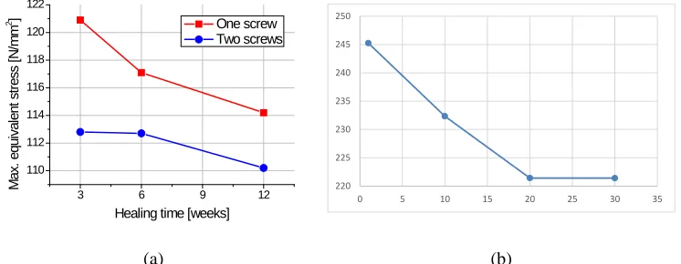
Fig. 25. Results of sensitivity study performed on femur-SIF assembly. (a) Maximal value of equivalent stress in SIF as a function of fracture healing time, when one or two locking screws
are used (Korunović et al. 2015b); (b) Dependence of stress in SIF on clamp distance at bar length of 250 mm (Korunović et al. 2015b)
The paper by Stojković et al. (2013) presents a part of design concept proving process, which is related to stress analysis of the Anatomically Shaped Lattice Scaffold design. The aim of the analysis was to identify functional relations between design parameters and elastic properties of the scaffold. The established relations are crucial for getting optimal values of elastic properties of scaffold that are required in a specific trauma-fixation case. The design study shown in the paper was done for the case of lattice scaffold anatomically shaped to the upper part of proximal diaphyseal trauma of rabbit tibia (Fig. 26). Design parameters which were altered within the design study were lattice’s struts cross-sectional area, density of the struts and angle of the struts intersection. The analysis showed that structural flexibility of latticelike scaffold may easily be changed through modification of three selected design parameters. In this way, it is confirmed that the proposed type of scaffold has an important capability to adapt its elastic properties to the required values, while being able to keep its great permeability and geometrical consistency to the particular anatomy of trauma region.
Parameter 3:
Elasticity of fracture zone (3 levels)
Parameter 2: Number of screws (2 levels)
Parameter 1: Bar length (3 levels)
3 6 9 12
110 112 114 116 118 120 122 M ax . equi val ent s tr es s [ N /m m 2 ]
Healing time [weeks] One screw Two screws 220 225 230 235 240 245 250
Fig. 26. Equivalent stress field on bone and scaffold shown separately. Struts angle is set to 72° (Stojković et al. 2013)
(a) (b)
Fig. 27. Sensitivity of lattice scaffold structural modulus ES: (a) to change of struts density; (b)
to change of struts angle (Stojković et al. 2013)
3. Tire design
For more than 15 years LIPS has been involved in the development and application of new methods in tire design related to computer aided design (CAD), simulation and manufacturing. Based on developed methods, procedures have been defined that are used in tire industry.
3.1 Tire geometry modeling and manufacturing
Stojković et al. (2003) presented a concept of inclusion of specific domain knowledge into computer aided tire design process, which enables substantial increase of productivity and reduces costs in early phases of the tire development. The proposed solution is based on Knowledge-Embedded Template concept as a form of new, but not an empty file of Computer Aided Product Development software. This kind of template has a set of user-defined knowledge contents of highly specific–tire design domain knowledge and experiences which are initially embodied in a new CAx file. The customized solution of tire design process proposed in the paper was tested within passenger and truck tire design process. Particular
0.08 0.10 0.12 0.14 0.16 0.18
500 1000 1500 2000 2500 3000 3500
ES
struts cross-section area
30 40 50 60 70 80
0 1000 2000 3000 4000 5000
ES
attention was paid to testing the use of this knowledge based solution within tread design process and corresponding manufacturing of tread ring of curing mold. The concept of Knowledge-Embedded template and its application on tire curing molds was also discussed and tested by Stojković et al. (2005) and Stojković et al. (2015), as shown in Fig. 28. During the testing, particular attention was paid to the capabilities of using this concept within an appropriate collaborative engineering environment and product-lifecycle management.
Stojković at al. (2004) presented a part of the functional passenger tire model built on the UML standards, which is directly related to functional ties between tread design features and the model of the manufacturing process of tread ring of the curing mold (Fig. 29). The functional model that is built succeeds to embed the entire semantics of concepts and actions of the corresponding models of development processes into itself. Explicit, implicit, and tacit knowledge related to this process also becomes embedded into the functional tire model, thus supplementing corporative knowledge base on tire. During the testing of the possibilities and usefulness of the tire functional model developed within UML, it was noticed that the existence of the tire functional model undoubtedly contributes to a remarkable increase of the reliability and swiftness of the tire development process.
Fig. 28. Content of tire design knoweldge is embodied in so called Knowledge Embedded Templates through form of initial built-in User Defined Knowledge Features
Fig. 29. Formalizing the tacit knowledge about tire tread design by UML - making an ontology of tire tread design features (Stojković et al. 2004)
Fig. 30. The one-pitch-segments made by SLM, SLS and DMLS
3.2 Simulation of tire behavior
Korunović et al. (2007) used structural static finite element analysis (FEA) to predict and improve mechanical behaviour of tyres. Special attention was given to various aspects of finite element (FE) model building, i.e. the choice of finite element types, definition of tire geometry, material modeling, creation of user subroutines used to define the direction and elastic moduli of tire reinforcements, and the choice of analysis options. FEA was performed to simulate tire mounting, inflation and static load support (Fig. 31, Fig. 32). Definition of most important mechanical properties of rubber and procedure for experimental determination of its tensile properties was also given.
(a) (b)
Fig. 31. 3D tire model for vertical loading analysis, with analysis steps depicted. Rim and ground are modeled as rigid bodies. (a) Load step 1 - mounting; (b) Load step 2 - inflation, load
step 3 - static loading (Korunović et al. 2007)
(a) (b) (c)
Fig. 32. Footprint shape and contact pressure distribution for: (a) under-loaded or over-inflated tire; (b) normally loaded tire; (c) overloaded or under-inflated tire. As it is often experienced in tire service, with increasing load contact pressure shifts towards tire shoulders and away from
the footprint center, which is often the cause of uneven tread wear (Korunović et al. 2007)
(a) (b)
Fig. 34. Results of cornering analysis. (a) Deformed shape of FE tire model and contact pressure distribution at left turn; (b) Side force vs. slip angle at speeds of 10 and 80 km/h,
variable coefficient of friction defined in FE model (Korunović et al. 2008)
(a) (b)
Fig. 35. FEA of tire rolling on the drum. (a) FE model; (b) Detail of deformed tire model during cornering analysis, at slip angle of 10° (Korunović et al. 2011)
(a) (b)
Fig. 36. (a) Calibration of friction coefficient, shown at contact pressure of 0.11 MPa; (b) Side force curves for the tire inflated to 0.2 MPa rolling at 10 km/h at vertical load of 3580 N,
calibrated vs. non-calibrated coefficient of friction (Korunović et al. 2011)
The paper by Korunović et al. (2012) deals with the level of detail that is necessary for representation of tread pattern in finite element tire models. Different methods for creation of tire tread mesh are systematized by two different criteria: the most common approaches and the finite element analysis type. An example from author’s experience, which describes the creation of finite element tire model with detailed tread for steady-state rolling analysis (Fig. 37) is presented. The paper also brings a head-to-head comparison of the response of simplified and detailed tread tire models, subjected to a range of finite element analyses, from footprint analysis at static loading conditions to steady-state rolling cornering analysis (Fig. 38).
10 100 1000
1.20 1.25 1.30 1.35 1.40 1.45 1.50 1.55 1.60 1.65 µ
v [mm/s]
p = 0.11 MPa Experiment Fit FEA Fit corrected FEA corrected
-10 -8 -6 -4 -2 0 2 4 6 8 10
-4000 -3000 -2000 -1000 0 1000 2000 3000 4000 FY [ N ]
α [deg]
p = 0.2 MPa, v = 10 km/h
Fz = 3580 N
Experiment FEA
(a) (b)
Fig. 37. Detailed tread tire model (a) Typical mesh segment formed by assembling of body and tread segments. Nodes on contacting surface are tied by DOF coupling; (b) Final 3D FE model
of the tire (Korunović et al. 2012)
(a) (b)
Fig. 38. Comparison of FEA results - detailed tread vs. simplified tire model (a) Comparison of contact pressure at the footprint; (b) Self-aligning torqueas a function of slip angle α, obtained
using simplified and detailed tread model (Korunović et al. 2012)
performance of a large number of geometrically different tire design variations may be analyzed in a very short time. Although a pilot one, the presented study has also led to the improvement of the existing tire design (Fig. 40).
Fig. 39. Dedicated CAD tire model, with some of the construction circles and curves shown (Korunović et al. 2014)
a) b)
c)
Fig. 40. Results of parametric study: contact stress distribution at vertical load of 2750 N. a) R1=53.8 mm; b) R1=64.4 mm; c) R1=75.0 mm. Original tire design (a), which contains the smallest sidewall radius, is characterized by distinct rise of contact pressure in the area of tire shoulders. In comparison with improved designs (b) and (c), maximum value of contact stress at
The identification of optimal tire design parameters for satisfying different requirements, i.e. tire performance characteristics, plays an essential role in tire design. In order to improve tire performance characteristics, formulation and solving of multi-objective optimization problem must be performed. Korunović et al. (2015) proposed a multi-objective optimization procedure for determination of optimal tire design parameters for simultaneous minimization of strain energy density at two distinctive zones inside the tire (Fig. 41). An advantage of the proposed procedure is reflected in the fact that multi-objective optimization is based on the Pareto concept (Fig. 42), which enables design engineers to obtain a complete set of optimization solutions and choose a suitable tire design. Furthermore, modeling of the relationships between tire design parameters and objective functions based on multiple regression analysis minimizes computational and modeling effort. The adequacy of the proposed tire design multi-objective optimization procedure has been validated by performing experimental trials based on finite element method (Table 2).
Fig. 41. Strain energy density at belt edge obtained by FE analysis of axisymmetric model (Korunović et al. 2015)
Fig. 42 The Pareto front of non-dominated solutions (Korunović et al. 2015)
f1 (N/mm2) f2 (N/mm2)
FE simulation experiment 0.03025 0.03663
Predicted 0.030377 0.036525
percentage error, % 0.4 0.3
Optimal combination of tire design parameter values: xd1=18 º, xd2=0.653 mm, xd3=1.351
Although the use of regression analysis (RA) speeds up and simplifies mathematical modeling process, the use of RA may be of limited applicability and reliability in cases where complex non-linear relationships exist between dependent and independent variables. As a consequence, the optimization results may not be satisfactory, i.e. there may exist big deviations between experimental and RA model predictions, particularity in the case of multi-objective optimization. Thus, the paper by Madić et al. (2015) aimed at determination of tire design parameters for multi-objective optimization of strain energy density at belt edge and chafer by the application of artificial neural networks (ANNs). Determination of the optimal tire design parameter values was performed by graphical optimization method (Fig. 42). The obtained multi-objective optimization results were compared with the results reported in study by Korunović et al. (2015).
a) b)
Fig. 43. 3-D response surfaces for strain energy density, (a) at belt edge; (b) at chafer (Madić et al. 2015)
4. Conclusions
A summary of research performed in LIPS laboratory in the last decade was presented in this review paper. For the sake of conciseness, it was narrowed to areas of bioengineering and tire design, which were the topics of most important projects undertaken by laboratory staff. Further joint research is currently performed in all of the described areas, according to newly set scientific and engineering goals.
Извод
Истраживања ЛИПС лабораторије у области биоинжењеринга и
дизајна пнеуматика
–
сажетак
резултата
Н. Коруновић1, М. Стојковић1, Ј. Миловановић1, Н. Витковић1, М. Трифуновић1, М.
Манић1, М. Трајановић1
1 Машински факултет, Универзитет у Нишу, Александра Медведева 14, 18000 Ниш,
Србија
имејл: [email protected] *главни аутор
Резиме
У раду су укратко представљени резултати репрезентативних пројеката на којима је учествовао истраживачки тим ЛИПС лабораторије. Развијена је нова методологија за израду геометријских модела костију, која подразумева препознавање типских форми на неправилној геометрији. Методологија омогућава једноставнију и бржу израду модела, на основу минималне количине података добијених нeинвазивним методама. Вршен је
прорачун напрезања коштано-зглобног система у присуству траума и имплантата као и
оптимизација структуре и положаја имплантата. Развијене су оригиналне матрице ткива
– скафолди и разрађена је методологија за усклађивање њихових еластичних својстава са
својствима околног ткива. Развијена је методологија за параметарско моделирање пнеуматика уз примену постојећег инжењерског знања као и за предвиђање механичког понашања пнеуматика у експлоатацији (при праволинијском котрљању, кочењу и скретању). Развијен је оригиналан приступ аутоматизованом креирању МКЕ модела на основу наменских CAD модела, који омогућава једноставну и брзу промену МКЕ модела, а самим тим и једноставно вршење структурне оптимизације.
Кључне речи: биомеханика, кости, скафолд, имплант, обрнути инжењеринг, неправилна геометрија, пнеуматик, ФЕМ, дизајн заснован на знању
References
Korunović N, Trajanović M, Stojković M (2007). FEA of tyres subjected to static loading, Journal of Serbian Society for Computational Mechanics, 1 (1), 87-98.
Korunović N, Trajanović M, Stojković M (2008). Finite Element Model for Steady-State Rolling Tire Analysis. Journal of Serbian Society for Computational Mechanics, 2(1), 63-79.
Korunović N, Trajanović M, Mitković M, Vulović S (2010). From CT scan to FEA model of human femur. IMK-14-Istraživanje i razvoj, 16(2), 45-48. (In Serbian)
Korunović N, Trajanović M, Stojković M, Vitković N, Trifunović M, Milovanović J. (2012). Detailed vs. Simplified Tread Tire Model for Steady-State Rolling Analysis, Strojarstvo: časopis za teoriju i praksu u strojarstvu, 54(2), 153-160.
Korunović N, Trajanović M, Stevanović D, Vitković N, Stojković M, Milovanović J, Ilić D (2013). Material characterization ISSUES in FEA of long bones. Proc. 3rd South-East European Conference on Computational Mechanics (Eds. M. Kojic, M. Papadrakakis and I. Tuncer), Kos, Greece.
Korunović N, Stojković M, Mišić D, Trajanović M. (2014). FEM based parametric design study of the tire profile using dedicated CAD model and translation code, Facta universitatis, Series: Mechanical Engineering, 12(3), 209-222.
Korunović N, Madić M, Trajanović M, Radovanović M. (2015a). A procedure for multi -objective optimization of tire design parameters, International Journal of Industrial Engineering Computations, 6(2), 199-210.
Korunović N, Trajanović M, Mitković M, Vitković N, Stevanović D. (2015b). A parametric study of selfdynamisable internal fixator used in femoral fracture treatment. Proc. NAFEMS World Congress 2015 inc. the 2nd International SPDM Conference, San Diego, CA.
Madić M, Korunović N, Trajanović M, Radovanović M (2015). Multi-Objective Tire Design
Optimization by Artificial Neural Networks. Proc. 5th International Conference on Information Society and Technology ICIST 2015, Kopaonik, Serbia.
Manić M, Stamenković Z, Mitković M, Stojković M, Shephard D E T (2015). Design of 3D model of customized anatomically adjusted implants. Facta Universitatis, Series: Mechanical Engineering, 13(3), 269-282.
Manić M, Mitković M, Stamenković Z, Vitković N (2015). Designing of Internal Dynamic Tibia Fixation 3D Model according to Mitkovic type TPL, Proc. 5th International Conference on Information Society and Technology ICIST 2015, Kopaonik, Serbia, 223-228.
Milovanović J, Stojković M, Trajanović M (2009). Rapid Tooling of Tyre Tread Ring Mould
Using Direct Metal Laser Sintering, JSIR-Journal of Scientific Industrial Research, 68(12), 1038-1042.
Milovanović Ј, Stojković M, Trajanović M (2012). Metal Laser Sintering For Rapid Tooling In Application To Tyre Tread Pattern Mould. Chapter 4 In: Shatokha V, editor. Sintering -Methods and Products, InTech, 73-90.
Milovanović (2014). Application of Additive Technologies in Fabrication of Anatomical Custom Made (Shaped) Scaffolds for Bone Tissue Reconstruction. Ph.D. Thesis, University of Niš, Faculty of Mechanical Engineering in Niš, Niš, Serbia.
Mišić D, Manić M, Vitković N, Korunović N (2015). Toward integrated information system for design, manufacturing and application of customized implants. Facta Universitatis, Series: Mechanical Engineering, 13(3), 307-323.
Ristić M, Manić M, Cvetanović B (2015). Framework for early manufacturability and technological process analysis for implants manufacturing. Proc. 5th International Conference on Information Society and Technology ICIST 2015, Kopaonik, Serbia, 460-463.
Stevanović D, Korunović N, Trajanović M, Trifunović M, Milovanović J, Stojković M (2012). Finite element model of human tibia and preliminary analysis. 11th international scientific conference MMA 2012, Novi Sad, Serbia.
Stojković M, Manić M, Trajanović M, Korunović N (2003). Customized Tire Design Solution Based on Knowledge Embedded Template Concept, Proc. 22nd Annual Conference on Tire Science and Technology, Tire Society, Akron, Ohio, U.S.
Stojković M, Manić M, & Trajanović M (2005). Knowledge-Embedded Template Concept. CIRP - Journal of Manufacturing Systems, 34 (1).
Stojković M, Trajanović M, Vitković N, Milovanović J, Аrsić S, Mitković M (2009). Referential Geometrical Entities for Reverse Modeling of Geometry of Femur,
Computational Vision and Medical Image Processing – VipIMАGE, Porto, Portugal, CRC
Press/Balkema, Taylor & Francis Group. 189-195.
Stojković M, Milovanović J, Vitković N, Trajanović M, Grujović N, Milivojević V, Milisavljević S, Mrvić, S (2010). Reverse modeling and solid free-form fabrication of sternum implant. Australasian Physical & Engineering Sciences in Medicine, 33(3), 243-250.
Stojković M, Milovanović J, Vitković N, Trajanović M, Arsić S, Mitković M (2012). Analysis of femoral trochanters morphology based on geometrical model, JSIR-Journal of Scientific Industrial Research, 71(3), 210-216.
Stojković M, Korunović N, Trajanović M, Milovanović J, Trifunović M, Vitković N (2013). Design Study Of Anatomically Shaped Latticed Scaffolds For The Bone Tissue Recovery. Proc. 3rd South-East European Conference on Computational Mechanics (Eds. M. Kojic, M. Papadrakakis and I. Tuncer), Kos, Greece.
Stojković M, Trifunović M, Misić D, Manić M, Towards Analogy-Based Reasoning in Semantic Network (2015). Computer Science and Information Systems (ComSIS), 12(3), 979-1008.
Trajanović M, Korunović N, Milovanović J, Vitković N, Mitković M (2010). Application of computer models of Mitković selfdynabizable internal fixator in rehabilitation of femur traumas. Facta universitatis, Series: Mechanical Engineering, 8(1), 27-38.
Trifunović M (2016). Geometric modeling of objects with free-form elements supported by analysis of their semantic features. Ph.D. Thesis, University of Niš, Faculty of Mechanical Engineering in Niš, Niš, Serbia.
Vitković N, Milovanović J, Korunović N, Trajanović M, Stojković M, Mišić D, Arsić S (2013). Software System for Creation of Human Femur Customized Polygonal Models. Computer Science and Information Systems, 10(3), 1473-1497.
Vitković N, Veselinović M, Mišić D, Manić M, Trajanović M, Mitković M (2012). Geometrical models of human bones and implants, and their usage in application for preoperative planning in orthopedics. Proc. 11th International Scientific Conference MMA 2012 - Advanced Production Technologies, Novi Sad, 539-542.