A Comparative Application of Performance of the SEPIC
Converter Using PI, PID and Fuzzy Logic Controllers for
PMDC Motor Speed Analysis
Hilmi ZENK
Department Of Electrical-Electronics Engineering Engineering Faculty, Giresun University
Giresun, Turkey [email protected]
Abstract—DC converters are widely used in
industrial area. SEPIC converter is a suitable converter when the input voltage has got wide variations around the rated voltage. In this study presents an analysis of the dynamic performance on DC-DC SEPIC (Single Ended Primary Inductor Converter) converter which is driving Permanent Magnet DC Motor (PMDC Motor) with PI, PID and fuzzy logic controller implementation. One of the applications in which source side variations are wide is DC Motor applications. Therefore, importance is given to source side disturbance of SEPIC converter. Hence in this paper, a PID controller and fuzzy logic controller have been implemented to improve the dynamic and steady state performance of the SEPIC converter when source voltage is subjected to wide variations keeping the output voltage at a constant value at steady state. Simulation results have been obtained using MATLAB/SIMULINK. The percentage overshoot, rise time and settling time have been compared and analyzed.
Keywords—DC-DC converter, Fuzzy Logic controller (FLC), Proportional Integral (PI) control, Proportional Integral Derivative (PID) control, SEPIC converter, Permanent Magnet DC Motor (PMDC Motor).
I. INTRODUCTION
In recent years, with the rapid development of industry, electric power, and this power can be controlled by the Power Electronics Circuit was committed, the need for increased rapidly. AC-DC and DC-DC Motor Speed Control Units, Uninterruptible Power Supplies, Battery Chargers, Switch Mode AC-DC Power Supplies, Static devices such as voltage regulators, providing electrical power feeding the load that needs major industrial power electronics applications [1].
A DC-DC converters are widely used in regulated switch-mode dc power supplies and in dc motor drive applications. Often the input to the converters is an unregulated dc voltage, which is obtained by rectifying the line voltage, and therefore it will fluctuate due to changes in the line voltage magnitude [2].
In many industrial applications DC voltage value instead of a fixed value of the DC voltage is needed at different levels. Constant DC voltage level, different DC voltage levels are used to convert DC converter circuits. Input-output voltage values are used differently depending on the structure of the DC converter circuit. The first thing to be considered when selecting the converter structure input and output voltage values. For example, according to the input voltage value of the output voltage increases when the desired value is higher when using the structure-type DC converter, the output voltage value of the input voltage is lower than the value used when necessary to reduce such DC converter structure [3].
DC-DC converters are many different types. They all have advantages and disadvantages relative to each other. Some of the voltage converters to reduce some of the others in enhancing and increasing the reduction is used. DC-DC converters with fuzzy logic control algorithm incorporating all kinds of engineering applications can be applied successfully. Fuzzy logic control DC-DC converter and has a better performance as well as reduced costs. In parallel with the development of digital technology and digital control, the application of fuzzy logic in proportion to the power transformer developed [4].
II. SEPIC CONVERTERS
Vol. 2 Issue 12, December - 2016
Fig. 1. Simple circuit diagram of SEPIC converter
Fig. 2 shows the circuit when the power switch is turned on. The first inductor, L1, is charged from the input voltage source during this time. The second inductor takes energy from the first capacitor, and the output capacitor is left to provide the load current. No energy is supplied to the load capacitor during this time. Inductor current and capacitor voltage polarities are also marked.
-+ + Vo -L1 C1Vi L2 C2 R1
Fig. 2. SEPIC converter when switched ON
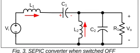
When the power switch is turned off, the first inductor charges the capacitor C1 and also provides current to the load, as shown in Fig. 3. The second inductor is also connected to the load during this time. The output capacitor sees a pulse of current during the off time, making it inherently noisier than a buck converter [5]. + - + Vo
-L1 C1
Vi L2 C2 R1
Fig. 3. SEPIC converter when switched OFF
The formulae of duty cycles are given as follows:
D i D V V V V V D 0 (min) 0 max (1) D i D V V V V V D 0 (max) 0 min (2)
For determining the inductance is to allow the peak-to-peak ripple current to be approximately 40% of the maximum input current at the minimum input voltage. The ripple current flowing in equal value inductors L1 and L2 is given by,
min 40 % 40 % 0 0 i i L V V I I
I
(3)
The inductor value is calculated by,
max 2 1 min D f I V L L L sw L i (4)
where fsw is the switching frequency and Dmax is the duty cycle at the minimum V input. The peak current in the inductor, to ensure the inductor does not saturate, is given by,
2 40 % 1 min 0 0 1 i D peak L V V V I I (5) 2 40 % 1 min 0 0 2 i D peak L V V V I I (6)
If L1 and L2 are wound on the same core, the value of inductance in the equation above is replaced by 2L due to mutual inductance. The inductor value is calculated by, max 2 1 2 2 min D f I V L L L sw L i
(7)
Power Switch Selection, the parameters governing the selection of the MOSFET are the minimum threshold voltage Vth(min), the on resistance RDS(ON), gate-drain charge QGD and the maximum drain to source voltage, VDS(max). Logic level or sublogic-level threshold switch’ should be used based on the gate drive voltage. The peak switch voltage is equal to Vin + Vout. The peak switch current is given by,
peak peak
peak L L
Q I I
I
2 2
1 (8)
The RMS current through the switch is given by,
2 0 0 0 0 1 min
min )( )
( i D i Q V V V V V V I I rms
(9)
G sw DO Q i DS Q I f Q I V V D R I
P ON p ea k
rms Q
rms max 0 1
2
1 1 ( min )
(10)
PQ1, the total power dissipation for MOSFETs includes conduction loss (as shown in the first term of the above equation) and switching loss as shown in the second term. IG is the gate drive current. The RDS(ON) value should be selected at maximum operating junction temperature and is typically given in the MOSFET data sheet. Ensure that the conduction losses plus the switching losses do not exceed the package ratings or exceed the overall thermal budget.
Input Capacitor Selection: The SEPIC has an inductor at the input. Hence, the input current waveform is continuous and triangular. The inductor ensures that the input capacitor sees fairly low ripple currents. The RMS current in the input capacitor is given by, 12 L C I I rms in (11)
The input capacitor should be capable of handling the RMS current. Although the input capacitor is not + Vo -D1
L1 C1
so critical in a SEPIC application, a 10 ìf or higher value, good quality capacitor would prevent impedance interactions with the input supply.
Output Capacitor Selection: When the power switch Q1 is turned on the inductor is charging the output current is supplied by the output capacitor. The RMS current in the output capacitor is,
min 0 0 0 i D C V V V I I rms (12)
The ESR, ESL and the bulk capacitance of the output capacitor directly control the output ripple. Assume half of the ripple is caused by the ESR and the other half is caused by the amount of capacitance.
peak peak L L ripple I I V ESR 2 1 50 % (13) sw ripplef V D I C 50 % 0 0 (14)
In surface mount applications, tantalum, polymer electrolytic and polymer tantalum, or multi-layer ceramic capacitors are recommended at the output [6].
SEPIC Coupling Capacitor Selection: The selection of SEPIC capacitor, Cs, depends on the RMS current, which is given by,
min 0 0 0 i D C V V V I I rms (15)
The SEPIC capacitor must be rated for a large RMS current relative to the output power. The voltage rating of the SEPIC capacitor must be greater than the maximum input voltage. The peak-to-peak ripple voltage on Cs,
sw s cs f C D I
V 0 max
(16)
State Space Analysis of SEPIC converter for continuous conduction mode can be done in two modes of operation. For a given network has two states in CCM, S1 on, S2 off and S1 off, S2 on, the response of the network in each state may be time weighted and averaged. The state equations can be expressed in matrix form as,
u B x A
X 1 1 (17)
D x C
Y 1 (18)
where X is the time derivative of the state variable vector, A1 is the state matrix, x is the state variable vector, B1 is the input matrix, u is the input and Y is the output. The state variables are taken as,
1 1 iL
x
(19)
2 2 iL
x
(20)
1 3 iC
x
(21)
2 4 iC
x
(22)
Mode 1: Switch S: ON (0< t < DT)
2 1 2 1 1 0 0 0 0 0 1 0 0 1 0 0 0 0 0 0 RC C L A 0 0 0 1 1 1 L B (23)
Mode 2: Switch S: OFF (DT < t < (1-D)T)
2 2 2 1 2 1 1 2 1 0 1 1 0 0 0 1 1 0 0 0 1 1 0 0 RC C C C L L L A 0 0 0 1 1 1 L B (24)
The state space averaged equation is given as,
Ad A d
x Bd B d
uX 1 2(1 ) 1 2(1 ) (25)
Therefore, the large signal model is expressed as,
u L v v i i RC C d C d C d C d L d L d L d L d v v i i C C L L C C L L 0 0 0 1 1 0 1 1 0 0 1 1 0 0 1 1 0 0 1 2 2 2 1 1 2 2 1 1 2 1 2 1 2 1 2 1 (26)III. SYSTEM CONTROL LOOP
The SEPIC converter is controlled with a voltage mode control scheme. The PWM module is configured for SEPIC mode with an independent time-base. The DC Link voltage is measured by the voltage sensors and sent to DSP control. This value is subtracted from the voltage reference in software to obtain the voltage error.
Vol. 2 Issue 12, December - 2016
PI – PID – FLC
CONTROLLERS
PWM CONVERTERSEPIC
DC MOTOR
SENSÖR
Vref
V
o
lt
a
g
e
E
rr
o
r
C
o
n
tr
o
l
O
u
tp
u
t
D
u
ty
C
y
c
le Vout
Voltage Feedback
+
-Fig. 4. A Block diagram of SEPIC voltage control loop
IV. CONTROL SYSTEMS MODELS
A. Proportional Integral (PI) Control
The control block diagram of the classical PI controller is given in Fig. 5. According to DC converter reference voltage input circuit, output voltage, is controlled by the PI controller. On activated equations are as follows. When you submit your final version, after your paper has been accepted, prepare it in two-column format, including figures and tables [8].
Fig. 5. PI Controller Block Diagram
B. Proportional Integral Derivative (PID) Control
The PID controller is the most common form of feedback. It was an essential element of early governors and it became the standard tool when process control emerged in the 1940s. The “textbook” version of the PID algorithm is described by equation (2).
dt t de T d e T t e K t
u d
t
i 0
1 )
( (27)
where y is the measured process variable, r the reference variable, u is the control signal and e is the control error (e = ysp − y). The reference variable is often called the set point. The control signal is thus a sum of three terms: the P-term (which is proportional to the error), the I-term (which is proportional to the integral of the error), and the D-term (which is proportional to the derivative of the error). The controller parameters are proportional gain K, integral time Ti, and derivative time Td [9].
C. Fuzzy Logic Control
The first is a small steam engine as the control for fuzzy logic control was carried out by Mamdani and Assilian. Fuzzy logic control algorithm consists of a set of rules and linguistic terms to express an intuitive control for fuzzy sets and fuzzy logic to evaluate the rules used [10-11].
Fig. 6. FLC Controller Block Diagram
As is known, the structure of fuzzy logic controller consists of three parts. If you need a brief look at these sections, the first as "The Blur" phase, the absolute values are converted to fuzzy values. Then, fuzzy rules, fuzzy values are processed "Rule processing and decision-making" phase, and finally, "defuzzification" step, the exact result is converted to fuzzy. Fuzzy logic control system is shown in Fig. 6. [12].
V. SIMULATION OF THE FULL SYSTEM
In Fig. 7. shown the whole system, in turn, is connected to the PID and FLC. These controllers, variable speed error between the reference and the output signal audited by the push-pull converter is PMDC motor actual speed with PWM method determines the position of the MOSFET or ideal switches. SEPIC converter determines the output voltage of the switch position. This voltage determines the speed of the motor.
VI. CONCLUSION
In MATLAB / Simulink programming, the variable reference speed applied to PI, PID and Fuzzy based control have been made, the SEPIC converter output speed PI was observed for PID and fuzzy controlled systems. PI controlled system simulation results are shown in Figure 8, Figure 9 and Figure 10.
Fig. 9. SEPIC converter with PI controller 0.5s - 1s responce
Fig. 10. SEPIC converter with PI controller 1.6s – 2.5s responce
PI controlled system simulation results are shown in Figure 11, Figure 12 and Figure 13.
Fig. 11. SEPIC converter with PID controller 0s - 3s responce
Fig. 12. SEPIC converter with PID controller 0.5s - 1s responce
Fig. 13. SEPIC converter with PID controller 1.6s – 2.5s responce
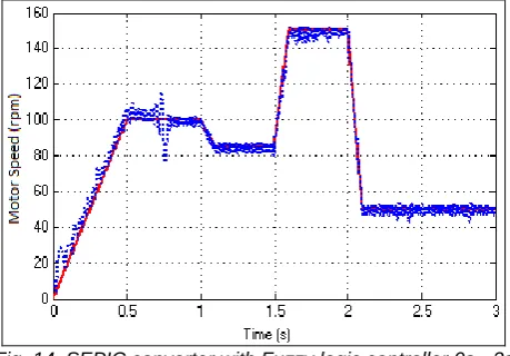
Fuzzy controlled system simulation results are shown in Figure 14, Figure 15 and Figure 16.
The Fuzzy logic control method can easily be applied SEPIC converters. In this study, the voltage applied to the motor to control the speed PMDC must be changed over time, and reduces both can increase the SEPIC converter voltage converter types are selected. Converter control conventional PI, PID and Fuzzy Logic control were performed separately.
Vol. 2 Issue 12, December - 2016
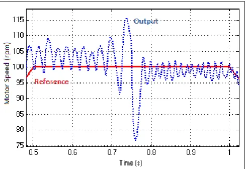
Fig. 15. SEPIC converter with Fuzzy logic controller 0.5s - 1s responce
Fig. 13. SEPIC converter with fuzzy logic controller 1.6s – 2.5s responce
The performance of a PMDC system with MATLAB/Simulink circuit is compared with a Sepic Converter driver designed in this study. The results show that the PID supervised system gives the best response. As shown in the graphs obtained under Fuzzy Logic control, there is a serious effect on system characteristics between fuzzy logic success due to control strategy and decision making, based on rule base. Similar to PID control, PI control provided better dynamic performance than fuzzy logic.
REFERENCES
[1] H. Zenk, and A. S. Akpinar, "Dynamic Performance Comparison of Cúk Converter with DC Motor Driving and Using PI, PID, Fuzzy Logic Types Controllers." Universal Journal of Electrical and Electronic Engineering, vol. 2, no. 2, pp. 90-96, 2014.
[2] N. R. B. M. Sarmin, “Analysis And Construction Of Push Pull Converter,” Degree of Bachelor, Electrical Engineering (Industry Power), Kolej Universiti Teknikal Kebangsaan, Malaysia, 2006.
[3] K. M. Smedley, and C. Slobodan, “One-Cycle Control of Switching Converters”, IEEE Transactions on Power Electronics, vol. 10, no. 6, pp. 625-634, 1995.
[4] İ.Sefa, N. Altın, Ş.Özdemir , “dSPACE Based Fuzzy Logic Controlled Boost Converter,” presented at the 4th International Conference on Technicaland Physical Problems of Power Engineering TPE-2008, University of Pitesti, Pitesti, Romania, 2008.
[5] R. L. Josephine, A. Padmabeaula, A. Dhayal Raj and R. L. Helen Catherine, “Simulation Of Incremental Conductance MPPT With Direct Control And Fuzzy Logic Methods Using Sepic Converter”, Journal of Electrical Engineering, vol.13, no 3. pp.91-99, 2013.
[6] J. Leema Rose and B. Sankaragomathi, “Design, Modeling, Analysis and Simulation of a SEPIC Converter”, Middle-East Journal of Scientific Research vol. 24 no. 7, pp. 2302-2308, 2016.
[7] Phuong L. M., Dzung P. Q. , Huy N. M. , Phong N. H., “Designing an uninterruptible power supply based on the high efficiency push–pull converter”, University of Technology,VNU-HCM, 2013.
[8] H. Zenk, “Comparison Of Cúk Converter With Dc Machine Driving And Using Different Types Controllers”, Journal of Multidisciplinary Engineering Science Studies JMESS, vol.2, no 1. pp. 198-202, 2016.
[9] C. Elmas, M.A. Akcayol, T. Yigit, “Fuzzy PI Controller For Speed Control of Switched Reluctance Motor”, J. Fac. Eng. Arch. Gazi Univercity, Vol 22, No.1, pp. 65-72, 2007.
[10] M. Sekkeli, C. Yıldız H. R. Özçalık. “Bulanık Mantık ve PI Denetimli DA-DA Konvertör Modellenmesi ve Dinamik Performans Karsılastırması”, K.S.Ü., Mühendislik-Mimarlık Fakültesi, Elektrik-Elektronik Bölümü, K.Maraş, 2010.
[11] H. Zenk, O. Zenk, A. S. Akpinar. “Two Different Power Control System Load-Frequency Analysis Using Fuzzy Logic Controller”, INISTA 2011, Dogus University, İstanbul, Turkey, 2011.