720 |
P a g e
IMPLEMENTATION AND PERFORMANCE
EVALUATION OF MIMO TECHNIQUE FOR HIGH
DATA RATE WIRELESS OPTICAL
COMMUNICATION SYSTEM IN TURBULENT
ATMOSPHERE
Ali Q. Baki
1, Dr. Shehab A. Kadhim
2, Dr. Salah Aldeen A. Taha
31,3
Laser & Optoelectronics Engineering Dept., University of Technology, Iraq
2
Laser & Optoelectronics Research Center, Ministry of Science & Technology, Iraq
ABSTRACT
The data rate on the order of gigabits per second of Free Space optical communication (FSO) system in turbulent channel suffers random fluctuations in the intensity and phase of the received signal. For mitigation of this effect, multiple input multiple output (MIMO-FSO) system performance with spatial diversity overatmospheric turbulence channels was considered in this work. Obtained results demonstrate that MIMO performance mitigation techniques have high link availability and reliability of FSO system under wide range of atmospheric turbulence conditions.Data rate enhances results are achieved without any bandwidth or power expansions and the bit error rate (BER) at the receiver is maintained below 10−9. We assume intensity modulation and on-off keying with NRZ type and present the BER performance of single-input single-output (SISO-FSO), (2Tx × 2Rx) and (4Tx × 4Rx) (MIMO-FSO) configuration systems with (155 Mbps) over this channel model. Both techniques of FSO systems (SISO and MIMO techniques) have been implemented experimentally through two approaches, laboratory and real field prototypes. It has been observed for (MIMO-FSO) link that increasing the system speed was almost linearly with the number of transmitting units.
Keywords: Data Rate of Communication, FSO, SISO, MIMO, Visibility, Atmospheric Turbulence.
I. INTRODUCTION
Free Space Optical (FSO) communications is the best practical solution to create abroad band three dimensional
global communications grid among ground, airborne nodes and satellite due to its ease of deployment, huge
available bandwidth, tolerance of bandwidth reuse and ingrained security at physical layer. In laser beam, the
total loss due to absorption and scattering. However, atmospheric condition such as haze, fog, dust, smoke and
rain turn the propagation environment into a multiple scattering medium and hence introduce laser pulse
broadening in time and space. Intensity modulation and direct detection (IM/DD) FSO communication is a low
cost and high bandwidth access technique, which has recently received significant attention and commercial
721 |
P a g e
its best under all weather conditions, prudent measures must be taken in the design of transmitter and receiver.More specifically, multiple transmitters and multiple receivers can be used to combat the turbulence induced
fading and to compensate for pulse attenuation and broadening caused by absorption and scattering, this
technique is also known as a diversity technique.Moreover, the possibility for temporal blockage of the laser
beams by obstructions is further reduced and longer distances can be covered through heavier weather
conditions [2].
In digital communications, one is interested in the peak of received power waveform in order to recognize the
signal from steady background radiation. In a receiver unequipped with appropriate countermeasure techniques,
hence inter symbol interference occur because of overlapping pulse tails on adjacent symbol intervals, and thus
limits the realize bit rate. As a result, the receiver should have a small Field Of View (FOV) and has to resort to
Line Of Sight (LOS) photons. It has been shown that increasing number of lasers and detectors in a system,
diversity gain can be achieved; an improvement in the reliability of the system can be had. This work focuses on
the performance analysis of optical MIMO systems in various weather conditions environments [3].
1.1 Free Space Optical Communication System
Free space optical (FSO) communication is a hopeful solution for high data rate point to point communication
system. An outdoor FSO link is essentially based on LOS, thus, its spatial isolation from potential interferers is
sufficiently maintained by its narrow beam width profile, but the narrow laser beam width is the pointing and
tracking requirements in the event of misalignment. This can be corrected using active tracking [4]. All FSO
systems consist from three main stages:
1.2 Optical Source (Transmitter)
Light Emitting Diode (LED) and Laser Diode (LD) are the two basic source option for FSO systems. The choice
between LEDs and LDs depends on the application and the configuration, adding to the cost. LED is use for
short distance indoor applications that require degree of mobility[5]. Also, LED circuits are simple and LED do
not require constancy against temperature changes. On the other hand, LD is often prefer for high speed directed
LOS links in outdoor. LD can also use at higher modulation average than LED
[6].
1.3 Optical Detector (Receiver)
The main types of a photodetector for FSO are; PIN photodiodes and APD[7]. A PIN photodetector is simple in
structure and utilize but it is less sensitive than an APD. The increased power margin presented by APD delivers
a system that is more robust to pointing inaccuracy and other losses [8].Hence, it should be noted that increase
in the receiver aperture area will also increase the amount of background noise collected by the receiver.
Therefore, diversity technique for mitigating the effect of turbulence in the atmosphere can operate on time,
frequency and space. In this case, instead of single large aperture, an array of smaller receiver aperture is used
so that multiple copies of the signal that are mutually uncorrelated can be transmitted either in time or frequency
or space. This will improve the link availability and BER performance of the system. It also limits the need of
722 |
P a g e
1.4 Atmospheric Channel
As we know any communication system need medium to make a communication link and communication link
has a direct effect on detector by limiting signal to noise ratio (SNR) and bit error rate (BER). There are two
types of optical channel: optical fiber and free space or the atmosphere. The atmosphere is the mixture of gases
and different particle of materials formed a multi layers surrounded the earth[10]. This nonhomogeneous fluid
make a different types of losses that lead to make a limitation for communication system. A spatial diversity
technique which uses multiple transmitter/receiver combination improves the link performance by reducing
fading induced by atmospheric turbulence. This further improves the received power at the receiver[11].
II. ATMOSPHERIC CHANNEL MODELING
The refractive index varies randomly through the different turbulent eddies and causes phase and amplitude
variations of the wave front. Turbulence can also cause the random drifts of optical beams and can induce beam
focusing[12]. To design a high performance optical communication link for the atmospheric FSO channel
several Probability Density Functions (PDFs) have been proposed for the intensity variations at receiver of
optical system [13]. The fading strength depends on link length, wavelength of optical radiation and refractive
index structure parameter 𝑐𝑛2 of the channel. This model is mathematically tractable and characterized by the
Rytov variance𝜎𝑅2. The turbulence induced fading is termed weak when 𝜎𝑅2<1 and this defines the limit of
validity of the model [14]:
𝜎𝑅2= 1.23 𝐶𝑛2𝐾7/6L11/6 (1)
Where 𝑘 = 2𝜋 𝜆 is the optical wave number, L is propagation distance.
The impact of PSF distortion is more severe on optical imaging systems, where the spatial impulse response
determines the image resolution and quality [15]. When misalignment fading occurred, diversity gain is
independent on numbers of transmitters and receivers but with atmospheric fading diversity gain is proportional
to the numbers of transmitters and receivers. In this paper two main distribution models depended (Log-normal
Distribution and Gamm-Gamma Distribution)to explain spatial diversity of the SISO and MIMO systems and
diversity gain have been analyzed. Diversity gain is linearly proportional with number of paths from transmitter
to receiver [16]. Log-normal distribution has been the most widely used as a statistical model for the random
irradiance experienced over atmospheric channels when the strength of turbulence increases Gamm-Gamma
Distribution model used because it cover all conditions weather [17].
2.1 Log-normal Distribution Model
The lognormal model assumes the log intensity of the laser light pass the turbulent atmosphere to be distribute
normally. Thus the function of probability density of the received irradiance is given by [18]:
𝑓 𝐼 = 1
(2𝜋𝜎𝑅2)
1 2 𝐼
exp −(𝐼𝑛 𝐼 𝐼0 +𝜎𝑅
2 )22
2𝜎𝑅2 , 𝐼 ≥ 0 (2)
Where (I) is the irradiance at the receiver and Io signal irradiance without scintillation. According to this model
diversity gain of MIMO FSO channels can be calculated with different scenarios based on the random
723 |
P a g e
misalignment the diversity gain is linearly proportional with the number of transmitters and receivers.Furthermore in the presence of misalignment fading the logarithm of the outage probability is linearly
proportional to log(SNR), but in the absence of misalignment fading the logarithm of the outage probability is
linearly proportional to log(SNR)2 [19].
2.2 Gamm-Gamma Distribution Model
Gamma-Gamma distribution model of turbulence is based on such modulation process which assumes that the
small scale and large scale effects are responsible for the changes occurring in the path of radiated light signal
travelling through turbulent atmosphere. This model is a common model and it was supposed in this work
[20].There is a statistical model that factorizes the irradiance as product of two independent processing random
each of them with a Gamma PDF. The PDF of the intensity fluctuation is given by [14]:
𝑓 𝐼 =2 𝛼𝛽 𝛼 +𝛽
2
𝛤 𝛼 𝛤 𝛽 𝐼
𝛼 +𝛽
2 −1𝐾 𝛼 −𝛽 2 𝛼𝛽𝐼 , 𝐼 > 0 (3)
Where Γ(.) is the gamma function, Kα-β (.) is the modified Bessel function of the second kind and order α-β. α
and β: are PDF parameters describing the scintillation experienced by plane waves, and in the case of zero-inner
scale are given by equation (4 and 5) [6]:
𝛼 = 1 exp 0.49 𝜎𝑅2
1+1.11 𝜎𝑅
12 5
7 6
− 1 4 ; 𝛽 = 1 exp 0.51 𝜎𝑅2
1+0.69 𝜎𝑅
12 5
5 6
− 1 (5)
It was observed for moderate to strong turbulence regime, Gamma-Gamma distribution provides the best fit to
irradiance statistics. In case of aperture diameter larger than the coherence length of the atmosphere, the
irradiance statistics appear to be log-normal.According to Gamma-Gamma distribution BER performance can be
evaluated, the optimum decision metric for OOK is given by [20]:
𝑃 𝑟׀𝑜𝑛, 𝐼𝑚𝑛 ≶𝑜𝑓𝑓𝑜𝑛 P(r׀𝑜𝑓𝑓, 𝐼𝑚𝑛) (6)
Where r = (r1, r2...rN) is the received signal vector.
The conditional bit error probabilities are given by:
𝑃𝑒 𝑜𝑓𝑓׀𝐼𝑚𝑛 = 𝑃𝑒 𝑜𝑛׀𝐼𝑚𝑛 (7)
= 𝑄( 1
𝑀𝑁
‾𝛾
2 ( 𝐼𝑚𝑛)
2 𝑀
𝑚 =1 𝑁
𝑛=1 ) (8)
Where N: the number of receiver, M: the number of transmitter. Therefore, average error rate can be expressed
as: 𝑃𝑀𝐼𝑀𝑂 = 𝑓 𝐼 𝑄 ( 𝐼 1 𝑀𝑁 ‾𝛾
2 ( 𝐼𝑚𝑛)
2 𝑀
𝑚 =1 𝑁
𝑛 =1
)𝑑𝐼 (9)
Where fI(I) is the joint pdf of vector I = (I11, I12. . . IMN). On the other hand, the factor N is used to ensure that
724 |
P a g e
III. ATMOSPHERIC ATTENUATION CALCULATIONS
In general attenuation is the reduction in the strength of the signal as it propagates through the medium. It is
given as the ratio of the power of the transmitted signal to that of the received signal. The attenuation coefficient
depends on four individual parameters and in a function of wavelength; these parameters are molecular and
aerosol absorption coefficient, and molecular and aerosol scattering coefficients.The empirical formula to
calculate attenuation coefficient is given by [2]:
𝛼 𝜆 =3.912
𝑉 ( 𝜆 550)
−𝑞 (10)
Where V is visibility range, λ is wavelength of the light and q is the size distribution coefficient of scattering
related to size distribution of the droplets. For calculating the attenuation Kruse's model, Kim's models must be
used for fog condition:
Kruse’s Model:
Kruse model is widely used in the calculation to determine FSO equipment link budget. The attenuation
coefficient, and Kruse model predict the attenuation for any meteorological conditions. Kruse model of particle
size distribution is:
1.3 if V> 50 km
q= 1.6 if 6km<V<50 km (11)
0.585 V1/3 if V< 6 km
Kim’s Model:
The evaluation of the parameter q using Kruse model for visibility lower than 6km (0.585V1/3) was not
collected in heavy fog. Thus, for visibility, V < 1 km, its significance is in doubt. Therefore, a recent study
proposed another expression for the parameter q, which is called Kim model. It gives the particle size
distribution q as:
1.6 If V> 50 km
1.3 If 6km<V<50 km
q= 0.16 V + 0.34 If 1km < V < 6km (12)
V-0.5 If 0.5km < V < 1km
0 If V < 0.5km
For tropical region which no fog attenuation to consider, only haze attenuation to be calculated, Kruse model is
good enough since we do not need to consider for V <1 km.
IV. EXPERIMENTAL WORK
4.1 Laboratory Approach of MIMO-FSO Prototype
The aim of this work is study the effect of wavelength and beam divergence for both SISO and MIMO
techniques with test their reliability under different weather effects. The lab chamber has been designed to
generate and control different atmospheric conditions as smoke, fog and rain which is near as possible to real
field atmosphere. This chamber has been set up to be in between transmitter and receiver at distance between 1
725 |
P a g e
The transmitter unit is a LD which is commonly used in real field FSO systems with two wavelengths 650 nmand 850 nm to study the effect of wavelength in this system. One source has been used in SISO, while double
sources launched in MIMO system with 5cm distance between them. The receiver unit is mainly composed of
photo detector, amplifier, receiver optics and demodulator, in this work we used light power meter from Lambda
Scientific company (MODEL: LLM-2) to measure the received power in each set up and each weather condition
cases, the active area of this detector is 10mm.Different weather conditions generated in lab chamber like: fog,
rain and smoke. This chamber have a dimension of (15 x 20 x35 cm).A fog has been generated by water steam
(handmade water vaporizing) system and injected into the chamber, figure (1) shows the setup of the
experimental FSO system.
Fig. (1): The Experimental FSO setup
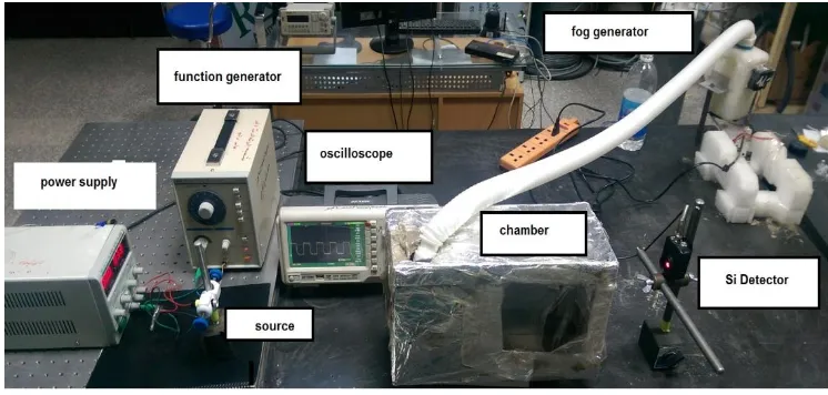
4.2 Real Field MIMO-FSO Prototype
In an earthly FSO, the communication system is typically located in the troposphere. All types of weather
phenomena is located in troposphere so its play a very detrimental role for FSO communications in lower
visibility range atmospheric conditions mainly due to rain, fog and snow.Flight Transport systems from LIGHT
POINT Company (model: FSA 155) have been used, this system is designed according to an optimal design of
MIMO-FSO communication system by lunching four semiconductor lasers in transmission unit and four optical
detectors in receiver unit.According to the characteristics of FlightStrata, Vertical Cavity Surface Emitting
Lasers (VCSEL) is very suitable to use in our MIMO-FSO system, this laser operate in an infrared wavelength
850nm [21].
The atmospheric chamber has been designed to control and simulate individual effects of (fog, smoke and rain)
because it's impossible to work in real turbulence and also hard to determine their levels. This chamber is made
from Perspex with dimensions (35 x 50 x 75) cm, the fog is generated by fog generator and the smoke by censer
and the rain by home shower. Also the detector of this system is Si-APD which is more sensitive due to an
internal amplification (avalanche) process.
To establish the FSO-MIMO system requirements the link head ought to connect to router board using optical
fiber (optical fiber is used to keep high data rate of optical communication). This router board from MicroTik
Company (model: RB2011 UiAs-IN) have been used in this system with CPU 600 MHz, and memory 64 MB.
726 |
P a g e
different cases, with a multitude of options. This router board considered as a heart of the system because itscontrol and manage the input and output data between link head and data source [22]. Two data sources have
been used in this work: desk top computer and camera (we use a camera to get live scene). Finally, the
MIMO-FSO experimental setup is shown in figure (2).
Fig (2): The photographic picture of the experimental setup
V. RESULT AND DISCUSSION
5.1 Results of Laboratory MIMO-FSO Prototype
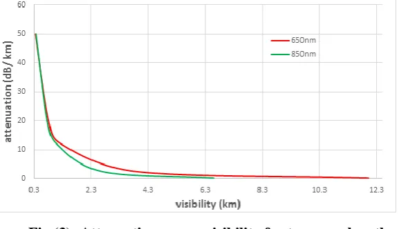
The visibility have been calculated for each weather conditions by Kim model. Figure (3) shows the plot of total
attenuation with visibility for 850nm and 650nm, its show clearly how the attenuation effect on the FSO system
and show the priority of 650nm wavelength on 850nm.
Fig (3): Attenuation verses visibility for two wavelengths
As it is shown above 650nm wavelength is better than 850nm also its easy install and control because it is
visible beam so we chose it in this section of work. Also as it mentioned in chapter three, the output power was
measured with different attenuation level by applying various weather condition. Then the attenuation was
calculated by using Beer-Lambert law, after that theses attenuation values were plotted versus received power at
727 |
P a g e
here, MIMO-FSO systems can significantly reduce the symbol error probability and provide diversity gain overSISO systems, so the MIMO technique is better than SISO technique.
Fig (4): Attenuation verses received power for both SISO and MIMO
5.2 Results of Real Field MIMO-FSO Prototype
In the originally, FlightStrata155 is a MIMO system with four transmitter and four receiver. To study the effect
of using SISO technique and MIMO technique from one side and number of transceiver from other side, we
have blocked some of them gradually from 1Tx/1Rx, 2Tx/2Rx, 3Tx/3Rx and finally 4Tx/4Rx and observed the
effectiveness on the communication link by watching WinBox software window which installed on the desktop
computer. Then the same steps have been repeated with smoky and foggy weather conditions, and the
attenuation effect has been noted by measuring the data rate and calculated the time which need to send
information. It has been observed the increasing in number of transceiver in MIMO technique make a system
get better performance but for engineering design and commercial calculation; 4TX/4RX is the optimal design for
MIMO system which is in the ideal range (5Km).
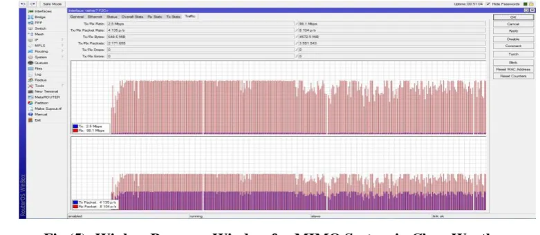
This system have been interfacing with a desktop computer by use a network switch. In clear weather we noted
there is no different in data rate when used 1Tx/1Rx, 2Tx/2Rx, 3Tx/3Rx and 4Tx/4Rx, but with smoky and
foggy weather case when the number of transceiver is increase the data rate is increase and the time need for
sent the file is decrease. Figure (5) and figure (6) shown the shot screen of the software with clear and foggy
weather conditions sequentially. And these figures also shown fluctuated of the send and receive signals and
their data rate.
728 |
P a g e
Fig. (6): Winbox Program Window for MIMO System in Foggy Weather
Its noteworthy Flightstrata155 is an industrial system and its for long distance (hundreds of meter) so to use it in
laboratory field for short distance special attenuators have been use to compensation the long distance (in FSO
communication the long distance mean more attenuation).All the measurement of real field system under
variance weather conditions have been collected in table (1). Because we work in laboratory field the different
in results between variance conditions weren’t large but in real field the difference will be larger and shown clearly, in fact that isn’t important point; the important point (which we get it) is the behaviors of the system in
SISO and MIMO techniques under different attenuators effect.
Table (1): The Results of Time Duration and Data Rate for Different FSO Cases
Case Data rate
Mbps
Time spend to
transfer the file (sec)
Clear weather
1Tx/1Rx 97 597
2Tx/2Rx 98.2 587
3Tx/3Rx 98 592
4Tx/4Rx 98.1 590
Smoky
weather
1Tx/1Rx 62.3 920
2Tx/2Rx 72 795
3Tx/3Rx 77.5 741
4Tx/4Rx 80.6 723
Foggy
weather
1Tx/1Rx 31 1775
2Tx/2Rx 42.7 1287
3Tx/3Rx 48.8 1128
729 |
P a g e
VI. CONCLUSIONS
The main objective to study (MIMO-FSO) technology is to provide an effective wireless communication
system. An effective communication system is that can transmit high data rate to a long distance with minimum
bit error rate so that better channel capacity can be achieved. The performance evaluation conclusions of optical
(MIMO-FSO) system shows:
1. MIMO-FSO system performance over a different atmospheric turbulence condition channel,it has been
observed that increasing the system channel capacity was almost1 linearly with the number of transmitting
units. Also the effectiveness of multi transmitters and receiver diversity helps in mitigating amplitude1
fading through overcome both amplitude and phase fluctuations. MIMO-FSO systems perform slightly
better than an equivalent1 SISO-FSO system in the presence of log-normal amplitude attenuation.
2. For the MIMO-FSO system Analysis of the different atmospheric turbulence condition, it has been observed
that when channel state over threshold condition; an improvement in (SNR) is directly proportional to the
number of transmitter and receiver units' .The (SNR) and the unconditional (BER) were evaluated
numerically for different system parameters. The degradation in system performance due to the channel
effectiveness and improvement in receiver sensitivity was determined numerically. Optimum system
parameters were determined for a given system BER, and we assume BER 10-9. (MIMO-FSO) systems
aresignificantly reducing the (BER), and provide diversity gain over SISO systems for different
signal-to-noise ratio (SNR) values, considering amplitude and phase perturbations. By increasing the number of lasers
and of receivers is able to achieve better performance from diversity gain.
REFERENCES
[1] Ashish Kumar, Aakash Dhiman, Devender Kumar and Naresh Kumar, "Free Space Optical Communication
System under Different Weather Conditions", IOSR J. Eng., vol. 3, no. 12, pp. 52–58, 2013.
[2] Dheeraj duvey and Er. Ritu gupta, "Review Paper on Performance Analysis of a Free Space Optical System",
International Journal of Application or Innovation in Engineering & Management, vol. 3, no. 6, pp. 135–139,
2014.
[3] Abd El–Naser A. Mohamed, Ahmed Nabih Zaki Rashed and Amina E.M. El-Nabawy, "The Effects of the Bad
Weather on the Transmission and Performance Efficiency of Optical Wireless Communication Systems", The
International Journal of Computer Science and Applications, vol. 4, no. 7, pp. 68–83, 2012.
[4] S. Term, S. Mission, R. M. Gebhart, E. Leitgeb, W. Propagation, M. Al Naboulsi, H. Sizun, F. Telecom, and
B. Dijon, “Measurements of light attenuation at different wavelengths in dense fog conditions for FSO applications,” no. 2004, pp. 1–35.
[5] S. Ethiraj, T. Gokulakrishnan and M. Baskaran, "Eliminating The Effects of Fog and Rain Attenuation For
Multiplexed Data Transmission On Free Space Optics", International Journal of Engineering Research and
Applications, no. March, 2013.
[6] Shlomi Arnon, John R. Barry, George K. Karagiannidis, Robert Schober and Murat Uysal, "Advanced Optical
Wireless Communication Systems", Published in the United States of America by Cambridge University
730 |
P a g e
[7] Oguzhan Timus, "Free space optical communication for navy surface ship plataforms", Master’s Thesis,Monterey, California. Naval Postgraduate School, 2004.
[8] Neda Cvijetic, Stephen G. Wilson and M. Brandt Pearce, "Free-space Optical MIMO Transmission with APD
Receivers", Proc. 39th Annu. Conf. Inf. Sci. Syst. (CISS), Balt. MD, pp. 16–18, 2005.
[9] Abdulsalam Ghalib Alkholidi and Khaleel Saeed Altowij M. Khatib, "Contemporary Issues in Wireless
Communications", Chapter 5: Free Space Optical Communications Theory and Practices, 2014.
[10] Rui Li, Changhong Ding, Hongzuo Li and Weida Zhan, "Study on Beam Energy and Impact on
Communication Quality in Space Optical Communications ", International Coriference on Electronics and
Optoelectronics, no. lCEOE, pp. 113–117, 2011.
[11] Harneet Kaur, Himali Sarangal, "Impact of Various Weather Conditions on Free Space Optics using 4X4
Transmitter/Receiver Combination Integrated with Different Ways of Amplification", International Journal of
Advanced Research in Computer and Communication Engineering, vol. 4, no. 3, pp. 388–393, 2015.
[12] Sana S. A., "An experimental study of the effects of atmospheric parameters on laser beam propagation",
Published thesis submitted to Military college of engineering, 2002.
[13] Vladimir Vovk and Glenn Shafer, "Kolmogorov’s Contributions To The Foundations of Probability", Finance,
vol. 39, no. 1, pp. 1–15, 2003.
[14] Haitham S.Khallaf, JoséM.Garrido Balsells, Hossam M.H.Shalaby and Seiichi Sampei, "SER Analysis of
MPPM-Coded MIMO-FSO System Over Uncorrelated and Correlated Gamma-Gamma Atmospheric
Turbulence Channels", Optics Communications Journal, vol. 356, pp. 530–535, 2015.
[15] Zeinab Hajjarian and Jarir Fadlullah, "MIMO Free Space Optical Communications in Turbid and Turbulent
Atmosphere (Invited Paper)",Journal of Communications, vol. 4, no. 8, pp. 524–532, 2009.
[16] Sangeetha N, Pathan Imran Khan and Vinayakamurthy Vignesh, "Analysis of Outage Probability and
Diversity Gain for MIMO Free-Space Optical Links", International Journal of Emerging Technology and
Advanced Engineering, vol. 4, no. 3, pp. 707–713, 2014.
[17] Tawabur Rahman and Shahid Iqbal and Monjurul Islam, "Modeling and performance analysis of free space
optical communication system", International Conference on [nfonnatics, Electronics and Vision, pp. 211–218,
2012.
[18] Mohamed R. Abaza, Raed Mesleh, Ali Mansour and Ayman Alfalou, "MIMO Techniques for High Data Rate
Free Space Optical Communication System in Log-Normal Channel", HAL Id:hal-00823258 pp. 1–5, 2013.
[19] Sergey Loyka and Georgy Levin, "On Outage Probability and Diversity-Multiplexing Tradeoff in MIMO
Relay Channels", IEEE Trans. Commun., vol. 59, no. 6, pp. 1731–1741, 2011.
[20] Mohammadreza A.Kashani, Murat Uysal and Mohsen Kavehrad, "On the performance of MIMO FSO
communications over Double Generalized Gamma fading channels", IEEE Int. Conf. Commun., vol.
2015-Septe, pp. 5144–5149, 2015.
[21] Flight Transport systems, Installation and Maintenance Manual/Light Pointe/ Flight Strata- FSA 155E,
USA.(2011).