119 | P a g e
STATIC STRUCTURAL ANALYSIS OF KNUCKLE
JOINT
Ms. Nilesha Patil
1, Mrs. Sayli M.Sable
2, Mr. Kashinath Munde
31
M E student Mechanical Engg. Design, APCOER, Pune 09, , Maharashtra
2
Lecturer, Pimpri chinchwad polytechnic, Mechanical Engg. Dept, Nigdi, Pune44, Maharashtra (India)
3
Asst. Prof. Department of Mechanical Engg, APCOER, Pune 09, Maharashtra (India)
ABSTRACT
The aim of the present paper is to study and calculate the stresses in Knuckle joint using analytical method. A
knuckle joint is used to connect two rods under tensile load. These joints are used for different types of connections
e.g. tie rods, tension links in bridge structure. In this, one of the rods has an eye at the rod end and the other one is
forked with eyes at both the legs. In this study, modelling and analysis of a knuckle joint is performed by using Finite
Element Method. The commercial finite element package ANSYS version 17 is used for the solution of the problem.
The knuckle joint takes tensile loads often, thus there is a need for quality design tools. The modelling of the knuckle
joint is done using 3D software. Here CATIA V5 has been used for modelling. The simulation part will be carried
out using the Analysis software, ANSYS. With the Boundary constrains and the tensile load applied, the knuckle joint
is analyzed and the values are tabulated.
Keywords: FEM, Knuckle Joint, Stress Analysis
I INTRODUCTION
A knuckle joint is used to connect two rods which are under the action of tensile forces, when a small amount of
flexibility or angular moment is necessary. It is basically a tensile joint. However, if the joint is guided, it may
support a compressible load. This joint can be readily disconnected for adjustments or repairs. The common
examples of the knuckle joints are: link of a roller chain, tension link in a bridge structure, tie rod joint of roof truss,
tie rod joint of jib crank, etc. A typical knuckle joint consists of three parts: an eye, a fork, and a knuckle pin. The
end of one rod is formed into an eye and the end of other rod is formed into fork with an eye in each of the fork leg.
The eye is inserted into the fork and after aligning the holes in the eye and fork, the knuckle pin is inserted through
them. The knuckle pin has a head at one end and at the other end it is secured by a collar and a taper pin or split pin.
The simple definition of stress is that force divided by area. If the force is perpendicular to the area and pulling away
120 | P a g e
Both tensile and compressive stresses come under general category of direct stress. The knuckle joint has wide
applications such as bicycle chain, Tractors, Automobile wipers, cranes, robotic joints structural members.etc
II FAILURE OF KNUCKLE
A knuckle joint may be failed on the following three modes
• Shear failure of pin (single shear).
• Crushing of pin against rod.
• Tensile failure of flat end bar.
III DESIGN OF KNUCKLE JOINT
Consider a knuckle joint connecting two rods and subjected to an axial tensile force P.
• P = axial tensile force on rods, N
• d = diameter of the rod, mm
• dp = diameter of the knuckle pin, mm
• D = outside diameter of the eye, mm
• t = thickness of the single eye, mm
• t1 = thickness of the fork, mm
• dh = diameter of the pin head and outside diameter of the collar, mm
• t2 = thickness of pin head and collar, mm
• σt = permissible tensile stress for fork end, N/mm
2
• τ = permissible shear stress for fork end, N/mm2
121 | P a g e
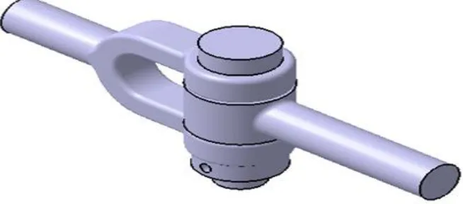
IV GEOMETRIC MODELLING
CAD model of steering knuckle was developed in 3D modelling software CATIA V5. it consists of Fork end, Single
eye, Collar, Split pin, knuckle pin.
Fig. 4.1 Solid model of Knuckle Joint
V ANALYTICAL DESIGN:
Assumptions:
1. Rod diameter d = 40mm
2. Load applied P = 9810 N (1Ton)
3. Diameter of knuckle pin (dp) = d
dp = 40mm
4. Thickness of single eye (t) = 1.25d = 1.25x40
t = 50mm
5. Thickness of fork (t1) = 0.75d = 0.75x40
t1 = 30mm
6. Outer diameter of eye (D) = 2d = 2x40
D = 80mm
7. Failure of fork end in tension (σt)
σt = 4.0875 N/mm2
8. Failure of fork end in shear (τ)
τ = 4.0875 N/mm2
Note: The tensile stress induced is calculated. This value must be less than the permissible tensile stress for the
122 | P a g e
VI MATERIAL SELECTION
There are several materials used for manufacturing of knuckle joint such as S.G. iron (ductile iron), white cast iron
and grey cast iron. But grey cast iron mostly used. Forged steel are most demanding material for this application.
For this Structural steel is used
Structural Steel
• Modulus of Elasticity : 2.0e5 MPa
• Poisson’s ratio : 0.30
• Density : 7.85e-6 kg/mm3
• Yield Strength : 250 MPa
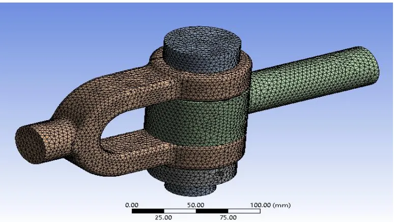
VII MESHING
The process for generating a mesh of nodes and elements consists of three general steps:
• CATIA offers a large number of mesh controls from which you can choose as needs dictate.
• Set the element attributes.
• Set mesh controls (optional).
It is not always necessary to set mesh controls because the default mesh controls are appropriate for many models. If
no controls are specified, the program will use the default settings to produce a free mesh. Alternatively, you can use
the Smart Size feature to produce a better quality free mesh.
Fig. 7.1 Meshing of Model in ANSYS
Element Type: Second order Tetrahedron
Elements count: 151529
123 | P a g e
VIII BOUNDARY CONDITION
Fig. 8.1 Boundary condition in ANSYS
The knuckle pin is fixed at one end at point C on the fork side. The axial tensile force of 9810 N is applied on the
other end.
IX Results
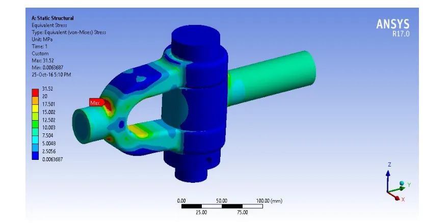
9.1 Von Mises
124 | P a g e
Application of the tensile axial force with given boundary conditions produces different stresses in the knuckle pin
the maximum stress is developed at the fork end which is 31.52MPa
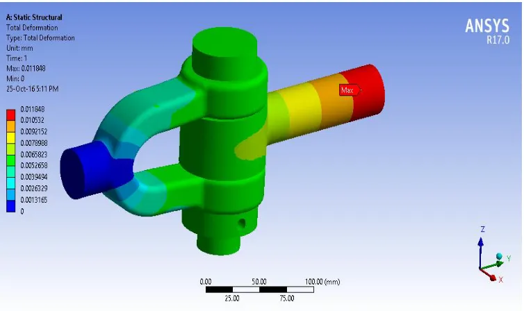
9.2 Deformation
Fig. 9.2.1 Deformation Results in ANSYS
X CONCLUSION
In this paper the tensile stresses for knuckle joint in static condition are calculated and analysed with ANSYS. The
maximum von mises stress is 31.52 MPa and minimum stress is 0.0063687Mpa. Allowable yield stress of steel is
210 MPa and our obtained von misses stress i.e. 31.52 MPa which is so much less than the yield stress. It forms the
basis of optimization.
XI ACKNOWLEDGMENT
Though I have taken efforts to complete this paper, it would not have been possible without the kind support and
help of some individuals and organization. I would like to extend my sincere thanks to all of them.
I am highly indebted to Asst. Prof. Kashinath Munde, APCOER, Pune for his guidance for providing necessary
information regarding this work. My thanks and appreciations also go to my colleague in completing this paper.
REFERENCES
[1] Mahesh P. Sharma, Denish S. Mevawala, Harsh Joshi, et.al, Static Analysis of Steering Knuckle and Its Shape
Optimization, IOSR Journal of Mechanical and Civil Engineering (IOSR-JMCE) e-ISSN: 2278-1684, p-ISSN:
2320-334X
[2] R. d'Ippolitoa, M.Hackb, S.Dondersa, et.al, Improving the fatigue life of a vehicle knuckle with a
125 | P a g e
[3]Sangamesh B. Herakal, Ranganath Avadhani, Dr.S.Chakradhar Goud, Structural Static Analysis Of Knuckle
Joint, International Journal of Engineering Research and General Science Volume 4, Issue 2, March-April,
2016, ISSN 2091-2730
[4] Pankaj Dulani, S. A. K. Jilani, Diameter and Spiral Thickness Optimization of Knuckle Joint Using Neural
Network, International Journal of Science and Research (IJSR) ISSN (Online): 2319-7064
[5] Shaik.John Bhasha, Hari Sankar Vanka, Modelling and Analysis of Knuckle Joint, International Journal &
Magazine of Engineering, Technology, Management and Research, ISSN No: 2348-4845
[6] Sourav Das1, Vishvendra Bartaria, Prashant Pandey, Analysis of Knuckle Joint of 30C8 Steel for Automobile
Application, International Journal of Engineering Research & Technology (IJERT),Vol. 3 Issue 1, January –
2014 IJERTIJERT ISSN: 2278-0181
[7] Sanjay Yadav, Ravi Kumar Mishra, Varish Ansari, et.al, Design and Analysis of Steering Knuckle Component,
International Journal of Engineering Research & Technology (IJERT), ISSN: 2278-0181, Vol. 5 Issue 04,