Prof. V. M. Chidri
,
3,Head of Department, Mechanical Engineering, MIT, Aurangabad.
Prof. A.J. Keche
44, Asst. Prof. Mechanical Engineering, MIT, Aurangabad. [email protected]
Abstract
In Centrifugal Pipe Casting machine, hot molten metal is injected from one end and the other end remains closed by a covering plate having standard dimension. This covering plate is locked by a worker with the help of a spanner. This covering plate again needs to be opened after completion of casting process for the extraction of the pipe from the mould. This paper discuss mainly focused on the analysis of locking plate and its new design so that the human interference must be reduced to higher extent. Thus large amount of time can be saved which in turn will increase the productivity & reduce the cost of production.
Keyword: Centrifugal Casting, ANSYS, FEM, Thermal Analysis, Structural Analysis etc.
1.0 INTRODUCTION
Centrifugal casting machine is used to mould cast iron pipes which are of great demand in the market. These pipes are used in great extent in various needs of our daily life like water supply pipes, sewage pipes etc. In this tough market, every company is trying utilized their money, their research, their expertise to stand well. The main aim of every industry is to reduce their manufacturing lead time, increase the rate of production, reducing cost of labour-in short they are adopting the policy of cost cutting in every possible ways to maximize their profit.
1.1 Dimensions Available From Industry
• Specifications for max 6 inch Diameter Pipe, • Internal Diameter of mould = 252 mm; • Outer diameter of covering plate = 250 mm; • Thickness of Covering plate = 12 mm; • Bore diameter = 60 mm;
• Max speed = 1500 rpm; • Average speed = 1200 rpm;
Figure 1.1 Molten metal Sprinking out from cavity.
The cavity must be closed down so that molten metal shoud not come out and the hazard to worker is reduced. Conventionally this locking and unlocking is done manually; which also increases chances of accidents to workers as it is at very high temperature.
Figure1.2 Attachement of Lock Plate (Manual)
2.0 COMPONENTS OF LOCK PLATE
2.1 Base plate
• 250 mm dia thickness 20 mm • Mild Steel material
• We can use any shape any material as per requirement.
Figure 2.2 Lever and Bearing
2.2 Guide Plate
• Mild Steel material
• Holes are provided on the circumference of the plate for insertion of locking wire. • Wire used are accelerator cables of two vehicles
• Guide plates are mounted on bearing as shown follows
Figure 2.3 Guide Plate with Lever and bearing
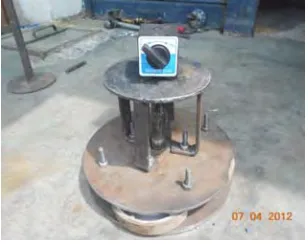
2.3 Total Assembly of Lock plate
Figure 2.5 Side View of Lock Plate with all arrangements
3.0 CALCULATIONS
• Centrifugal Force
Thickness of pipe =10 mm,
Diameter of pipe =152 mm,
Therefore, r = 76 mm,
Mass of Molten metal =15 kg,
Velocity of the molten metal =1200rpm
Centrifugal Force = m.v2 / r
= (15 X 202) / 76
= 45 N
Keeping tolerance of 50%, for our design safety,
Centrifugal force = 70 N
4.0 FEM ANALYSIS USING ANSYS
4.1 A General Procedure For Finite Element Analysis
Certain steps in formulating a finite element analysis of a physical problem are common to all such analyses, whether structural, heat transfer, fluid flow, or some other problem. These steps are embodied in commercial finite element software packages (some are mentioned in the following paragraphs) and are implicitly incorporated in this text, although we do not necessarily refer to the steps explicitly. The steps are described as follows.
4.1.1 Preprocessing
The preprocessing step is, quite generally, described as defining the model and includes
substitution to compute additional, derived variables, such as reaction forces, element stresses, and heat flow. As it is not uncommon for a finite element model to be represented by tens of thousands of equations, special solution techniques are used to reduce data storage requirements and computation time. For static, linear problems, a wave front solver, based on Gauss elimination, is commonly used. While a complete discussion of the various algorithms is beyond the scope of this text, the interested reader will find a thorough discussion in the Bathe book.
4.1.3 Postprocessing
Analysis and evaluation of the solution results is referred to as postprocessing. Postprocessor software contains sophisticated routines used for sorting, printing, and plotting selected results from a finite element solution. Examples of operations that can be accomplished include:
• Sort element stresses in order of magnitude. • Check equilibrium.
• Calculate factors of safety. • Plot deformed structural shape. • Animate dynamic model behavior. • Produce color-coded temperature plots.
4.2 Finite Element Generation
The IGES file is imported and meshing is done. Mesh Element type was Tetrahedran. Number of elements generated were 145831
Figure 4.2 Applied force of 70 N
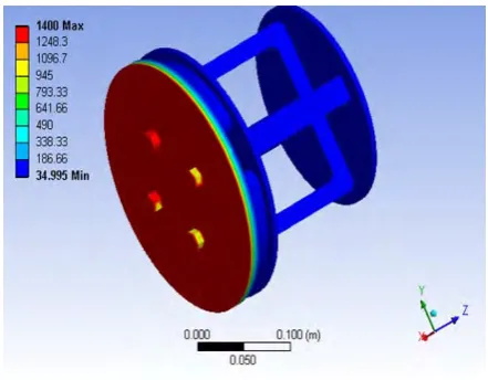
5.0 Results Observed
Following results were available after analysis is carried out
Figure 5.3 Temperature Distribution
6.0 References
[1] J.K.Kim, P.K.Rohatgi, “Interaction between moving cellular solidification front and graphite particles during centrifugal casting”, Materials Science and Engineering A244 (1998) 168-177.
[2] Numan Abu-Dheir,Marwan Khraisheh, Kozo Saito, Alan Male,”Silicon morphology modification in the eutectic Al-Si alloy using mechanical mold vibration”, Materials Science and Engineering A393 (2004) pp. 109-117.
[3] M. Au and K. M. Yu, A scaffolding architecture for conformal cooling design for rapid plastic injection [4] moulding, Int J Adv Manuf .Technol., Published online 8th June, 2006,
[5] L. Tang, C. Chassapis and S. Manoochehri, Optimal cooling system design for multi-cavity injection moulding, Finite Elements in Analysis and Design, 26 (1997), 3, pp 229-251.
[6] Zhiliang NING, P CAO, H. WANG, Jianfei SUN and Diankun LIU, J. Master, “Effect of cooling conditions on grain size of AZ91 Alloy”, , Sci., Technol., Vol. 23 No. 5, 2007.
[7] ASM International, Metal Handbook, Ninth Edition, Vol. 15 Casting pag. 296-307.
[8] Hengcheng Liao, Yu Sun and Guoxiong Sun, “Correlation between mechanical properties and amount of dendritic α-Al phase in as-cast neareutectic Al-11,6% Si alloys modified with strontium”, Materials Science and Engineering A335 (2002) 62-66.
[9] Q.G.Wang, “Micro structural effect on the tensile and fracture behaviour of aluminium casting alloy A 356/357”, Metallurgical and Materials Transaction, Vol. 34 A, December 2003, 2887-2899.
[10] ASM International, Aluminium-Silicon Casting Alloy: Atlas of Microfractografs, pags.1-9.
[11] S. Suresh, A. Mortensen, “Fundamentals of Functionally Graded Materials – Processing and Thermomechanical Behaviour of Graded Metals and Metal-Ceramic Composites”;
[12] ASM International and The Institute of Materials 1995, 1997; IOM Communications Ltd 1998.
[13] Wu Shi Ping, Liu Dong Rong, Guo Jing Jie, Li Chang Yun et al., (2006) : “Numerical simulation of microstructure evolution of Ti-6Al-4V alloy in vertical centrifugal casting”, Materials Science and Engineering A 426 240-249.