ANALYSIS OF SP’s
[4][5][7]
UNIT STEP
FUNCTION THROUGH EXAMPLES
SATYAPAL SINGH1, Dr. (Lt.) RAJEEV KUMAR SINGH2, SURUCHI RAWAT3,
SUSHESH SINGH4
1
AP, Department of ECE,PCCS, Greater Noida, UP, Pin 201306, India 2
Associate Professor, HOD Physics, Bhagwant University, Ajmer, Rajasthan, India 3,4
Student, JKG Senior Secondary School, Ghaziabad, UP, Pin 201009, India
Abstract
In the earlier research papers as mentioned in reference at serials numbers 4 through 9 at the last of this paper, I discussed SP’s proposed concept of elementary signals for Unit Step and Unit Ramp Functions. These elementary signals play a vital role in the study of signals. These elementary signals serve as basic building blocks for the construction of more complex signals. In fact, these elementary signals may be used to model a large number of signals which occur in nature. Based on the concept developed, in this paper some examples are solved to prove the theory or more clearly SP’s theory for Unit Step signals. Hence, it has been named as “ANALYSIS OF SP’s UNIT STEP FUNCTION THROUGH EXAMPLES”.
Keywords: SP’s – Satyapal’s, Angle – The angles at which shape of the elementary signal changes, Clockwise – The direction of watch, Anticlockwise – the opposite direction of watch.
1. Introduction
SP’s angle theory states that the elementary signals such as unit step and ramp functions can be represented by
angles too. To understand this, first the existing theory[1 through 3][10 through 16] for unit step functions is briefly narrated and then SP’s unit step function is explained[4][5][7] in a nut-shell. SP’s angle theory says that
the Unit Step functions can be defined with the help of two 90 degree angles in four steps which gives a new &
better idea to understand the Unit Step Function. Apart from this, when one is asked to construct a shape from a given equation, then normally he/she is provided with an equation that usually contains basic or elementary signals. Most of the students and engineers may be unaware to what to do for a given equation even after learning the existing theory. For this, I have developed “Concept of Angles” [4][5][7] theory that may be helpful in constructing the shapes from the given equation and in understanding the basic signals. Let us take the Unit Step signal function to explore the concept of angles.
2. Brief discussion of existing definition/theory and concept developed
Existing theory – The existing theory states that unit step u(t) function holds amplitude of unit value for time greater or equal to zero and amplitude is zero for rest of the times[1 through 3][10 through 16]. The continuous-time unit-step function is denoted by u(t) and it is mathematically expressed as –
u(t) = 1, when t >= 0
0, otherwise (that is for t < 0)
let x(t) = u(t) x(t) = u(t)
1
0 t
Figure 1. Continuous-time Unit Step Function u(t) based on existing theory.
SP’s concept - For this case, function u(t) can be represented in terms of angles as shown below –
0, when t < 0
u(t) = 1, 900 anticlockwise at t = 0 1, 900 clockwise for t > 0
This representation is nothing but the SP’s Unit Step Function[4][5][7]. To prove this concept or theory, some examples are solved. These solutions are helpful for the students as well as for the technocrats.
Thus Unit Step u(t) signal takes two 90 degrees shifts – first shift in anticlockwise direction and second shift in clockwise direction with a unit height (amplitude) and finally extends towards right side (positive) infinity. Hence, plotting of u(t) by using angles can be shown as in figure 2. This plot has total four steps, hence I will call it is a “STEP BY STEP” plot of unit step function. The steps can be referred in [5][7].
u(t) 900
1
900
0 t
Figure 2. Sketching function u(t) using angle theory, step 4.
Similarly, u(-t), -u(t) and –u(-t) can be plotted. For more details, refer [4][5][7].
3. Analysis of the theory developed through examples
Let us consider some examples to prove the concept developed. For this, let us take examples based on signal u(t).
Example 1. DRAWING OF u(t-2)
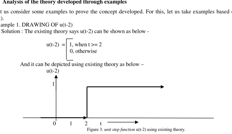
Solution : The existing theory says u(t-2) can be shown as below -
u(t-2) = 1, when t >= 2 0, otherwise
And it can be depicted using existing theory as below – u(t-2)
1
0 1 2 t
Drawing of u(t-2) considering SP’s theory -
Step 1. First assume that, in idle case when no signal is there, then every signal is assumed to be present on x-axis with zero amplitude. Hence, now for signal u(t-2) which has for positive time t, the signal line comes from negative infinity to t = 2 as shown in figure 4.
1
0 1 2 t
Figure 4. Plot of u(t-2) under no signal condition.
Step 2. As soon as the signal u(t-2) comes/appears then the signal instantly takes a 90 degree shift at t = 2 in anticlockwise direction and takes one straight line parallel to y-axis line. This situation is shown in figure 5.
1
900
0 1 2 t
Figure 5. Plot of u(t-2) as soon as signal appears at t = 2.
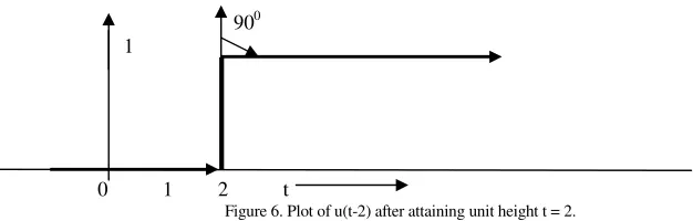
Step 3. After attaining a unit height again the shape takes a shift of 90 degree in clockwise direction and finally extends to infinity towards right. This is shown in figure 6.
900 1
0 1 2 t
Figure 6. Plot of u(t-2) after attaining unit height t = 2.
Step 4. Now, mix all the above steps and we get a new well defined diagram. The whole diagram can be shown as below for two 900 shifts. This figure clearly explains that it has two 90 degree angles.
900 1
900
0 1 2 t
Figure 7. Step by step plot of u(t-2) after mixing each step.
Example 2. DRAWING OF -u(t-2)
-u(t-2) = -1, when t >= 2
0, otherwise
And using existing theory, it can be depicted as below – -u(t-2)
0 1 2
-1
t
Figure 8. unit step function -u(t-2) using existing theory.
Drawing of function –u(t-2) using SP’s concept.
Step 1. First assume that, in idle case when no signal is there then the depiction line comes from negative infinity to t = 2. This situation is shown in figure 9.
x(t)= -u(t-2)
0 1 2
t
Figure 9. Plot of -u(t-2) under no signal condition.
Step 2. As soon as the signal -u(t-2) comes/appears then the signal takes a 90 degree shift in clockwise direction and takes one straight line parallel to x(t) i.e. parallel to y-axis line. For –u(t-2), follows parallel negative y-axis direction line. This is shown in figure 10.
x(t)= -u(t-2)
0 1 2
900 t
-1
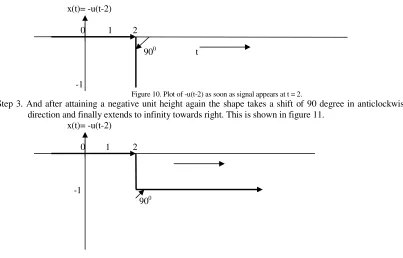
Figure 10. Plot of -u(t-2) as soon as signal appears at t = 2.
Step 3. And after attaining a negative unit height again the shape takes a shift of 90 degree in anticlockwise direction and finally extends to infinity towards right. This is shown in figure 11.
x(t)= -u(t-2)
0 1 2
-1
900
Figure 11. Plot of -u(t-2) after attaining negative unit height t = 2.
0 1 2 900
900 t
Figure 12.. Step by step plot of -u(t-2) after mixing each step.
Similarly, considering all the four steps, some example will be plotted without explaining each and every step.
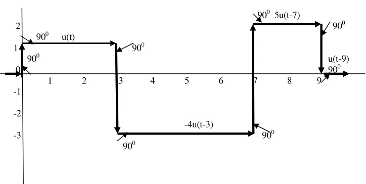
Example 3. Sketch the shape of the given equation – u(t) - 4u(t-3) + 5u(t-7) - 2u(t-9) Solution –
The solution is given below by keeping the given theory in the previous sections –
900 5u(t-7)
2 900
900 u(t)
1 900
900 u(t-9)
0 900
1 2 3 4 5 6 7 8 9
-1
-2
-4u(t-3)
-3 900
900
Figure 13. Step by step plot of equation u(t) - 4u(t-3) + 5u(t-7) - 2u(t-9).
Example 4. Sketch the shape of the given equation – u(t-2) - 2u(t-5) + 3u(t-7) - 2u(t-9) Solution –
The solution is given below by keeping the given theory in the previous sections – 900 3u(t-7)
2 900
900 u(t-2)
1 900
2u(t-9)
0 900
1 2 3 4 5 6 7 8 9
900 900 -1
900 -2u(t-5) -2
Figure 14. Step by step plot of equation u(t-2) - 2u(t-5) + 3u(t-7) - 2u(t-9)
Example 5. Sketch the waveform the expression – 5
Solution –
The solution is given below by keeping the given theory in the previous sections. Here it is worth note that this equation is given in a complex mathematical form without losing its generality. Hence, first we have to make the equation in proper mathematical form then we will draw the shape. The above equation can be written in following form –
x(t) = u(t)-3u(t-1)+3u(t-2)-3u(t-3)+3u(t-4)-3u(t-5)
2
900 900 900
1 u(t) 900 900 900
900
0 1 2 3 4 5 6 7 8 9
-1
-2 900 900
900 900 900
-3
Figure 15. Step by step plot of equation x(t) = u(t)-3u(t-1)+3u(t-2)-3u(t-3)+3u(t-4)-3u(t-5)
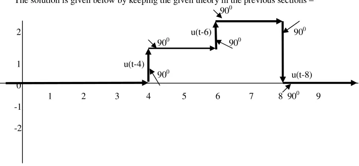
Example 6. Sketch the shape of the given equation –
u(t-4) + u(t-6) - 2u(t-8) Solution –
The solution is given below by keeping the given theory in the previous sections – 900
2 u(t-6) 900 900 900
1 u(t-4)
900 u(t-8)
0
1 2 3 4 5 6 7 8 900 9
-1
-2
Figure 16. Step by step plot of equation x(t) = u(t-4) + u(t-6) - 2u(t-8)
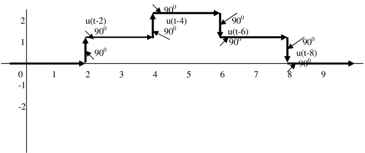
Example 7. Sketch the shape of the given equation –
u(t-2) + u(t-4) - u(t-6) - u(t-8)
Solution –
The solution is given below by keeping the given theory in the previous sections –
900 2 u(t-2) u(t-4) 900
900 900 u(t-6)
1 900 900
900 u(t-8)
900
0 1 2 3 4 5 6 7 8 9
-1
-2
Figure 17. Step by step plot of equation x(t) = u(t-2) + u(t-4) - u(t-6) - u(t-8)
4. Conclusion
When, I applied this theory to the B.Tech. (Subject : Signals and Systems) students, I found students not only grasped this theory but also solved a number of problems based on this. This paper is an outcome from the teaching experience and my related research papers. The students faced a lot of problems to understand the unit step function numerical problems. This work is an attempt to teach the students step by step construction procedure of unit step signal functions and this work has an attempt to explore the new and easy theory specially written for unit step related to the basic signal functions. No doubt the future studies will further explore my work in deep. On the basis of this theory, some other signals could be developed that will go long to the scientists and students. As no matter is available on the internet/books, hence I claim that this theory/analysis is
purely based on my research work/affords and has a bright chance to explore new theory and ideas on this.
Acknowledgement
I would like to thank to B.Tech. pursuing students who posed a lot of questions in the form of doubts and inclined me to think more and more to clarify their complex doubts. What I feel in this context that it is only the students for a teacher who can make a teacher gold from silver. Hence, I acknowledge my students and again I pay special thanks to my students who made me to reach at this stage where I could produce this paper.
References
[1] A.V. Oppenheim, A.S. Willsky with S. Hamid Nawab (2002). Signals and Systems, Second edition. Pearson Education,. [2] Simon Haykin, Barry Van Veen. (2004). Signals and systems. Second Edition. John Wiley & Sons (Asia) Pte. Ltd. [3] P. Ramakrishna Rao, (2008). Signals and Systems. First edition. Tata McGraw Hill.
[4] Satyapal Singh - own concept, based on teaching experience (2006 to till date).
[5] Satyapal Singh (2010): Proposed concept of Signals for Unit Step functions, IJEST, Vol. 2(9), pp. 4156-4162. [6] Satyapal Singh (2010): Proposed concept of Signals for Ramp Functions, IJEST, Vol. 2(9), pp. 4148-4155.
[7] Satyapal Singh (2010): Proposed concept of Signals for Unit Step Functions, World Congress on Engineering and Computer Science 2010, San Francisco, USA (20-22 October, 2010), Vol. 1, pp. 50-55.
[8] Satyapal Singh (2010): Proposed concept of Signals for Ramp Functions, World Congress on Engineering and Computer Science 2010, San Francisco, USA (20-22 October, 2010), Vol. 1, pp. 101-106.
[9] Satyapal Singh (2011): Concept of and Plot of Signals on Paper and in Oscilloscope, International Journal of Engineering & Technosciences - IJETS, Vol 2(2) 2011, pp. 214-220.
[10] M.J. Roberts (2003): Signals and Systems. Tata McGraw Hill Edition, New Delhi.
[11] John G. Proakis & Dimitris G. Manolakis (1997): Digital Signal Processing – Principles, Algorithms and Applications, 3rd
Edition. Prentice-Hall of India, New Delhi.
[12] Ziemer, R.E. Tranter, W.H. and Fannin, D.R. (1989): Signals and Systems Continuous and Discrete. Second Edition. New York, NY: Macmillan.
[13] Papoulis, A. (1977) : Signal Analysis. New York, NY, McGraw-Hill. [14] John G. Proakis & Dimitris G. Manolakis (2007): Digital Signal Processing, IVrd
Edition, Pearson Education Inc. [15] MJ Roberts (2003) : Signals & Systems, Fifth Edition reprint 2005, Tata Mc Graw Hill.
Satyapal Singh is currently working as A.P. in the Department of Electronics and Communication Engineering (ECE) at PCCS, Greater Noida, UP, Pin 201306, India, since 2006 where he teaches Several Courses in the area of Electronics and Communication Subjects. He has 17 years of glorious experience in Indian Air Force in technical field where he indigenized one of the direction finders in 1994 and saved Indian currency Rs. 60,000/- per rectification and awarded for his incredible act. He received his M.Tech. Degree in Electronics & Communication Engineering from M.D. University, Rohtak, Haryana in 2010 and M.Tech. (ALCCS) Degree in Computer Science from IETE, New Delhi. Apart from these, he holds MCM(Computer), MMS(Marketing), B.Tech. (ET-AMIETE), B.Sc. (PCM), Diploma(EC), DBM and D.Mat.M. He is Currently Pursuing Ph.D. in Electronics and Communication Engineering at Bhagwant University, Ajmer, Rajasthan, India. His main research interests are – Computer Networks, Signals and Systems such as some of the international published papers in journal and conference are - “Proposed Concept of Signals for Unit Step Functions” (USA-WCECS & IJEST), “Proposed Concept of Signals for Ramp Functions” (USA-WCECS & IJEST), “Concept of and Plot of Signals on Paper and in Oscilloscope” ( IJETS). Apart from this, five national papers are published. He is a life member of Institution of Electronics and Telecommunication Engineers (IETE).
Dr.(Lt.) Rajeev Kumar Singh is currently working as Associate Professor in Department of Physics (Head of the Department) at AIT, Ajmer, Rajasthan since July 2004 where apart from this he has been provided with designations such as – OIC examination, Chief Hostel Warden & Member of Discipline Committee. He is multiskilled personality since 1996 in the fields of industry & advertising Companies (as Marketing Manager) & Institution (as faculty). He was awarded lieutenant rank in NCC(Army Wing). He received his Ph.D. degree from L.N. Mithila University, Darbhanga, Bihar and M.Sc.(Physics) from A.N. College, Bodhgaya University Patna, Bihar.
Suruchi Rawat is currently pursuing senior secondary school. She scored 96.4% in secondary school in 2009. She holds first position in the school since class first to till date. She is awarded many times for participation in different types of programs such as cultural, debates, sports etc. She expects to develop her career in the field of engineering hence her keen interest made her to participate in developing this research paper.