Implementation of a Low Pin Count Test
and Scan Compression
Y. Durga Vani*
Department of Electronics and Communication Engineering Maharaja Vijayaram Gajapathi Raj College (A) Vizianagaram - 535002, Andhra Pradesh, India
Dr. M. Satanarayana*
Professor, Department of Electronics and Communication Engineering Maharaja Vijayaram Gajapathi Raj College (A)
Vizianagaram - 535002, Andhra Pradesh, India
Abstract:
The continuous increase in design sizes and acquisition of advanced types of fault models to meet rigorous quality standards are resulted in an exponential growth in test data volume and test cost. Scan compression technology significantly minimizes the cost of test by compressing the test patterns and applying them in low test time with limited test pins. EDT compression is inherently an excellent low pin count testing solution for devices with very few test pins. For designs with extremely test-pin limited, dedicated low pin count test (LPCT) controllers can be used along with EDT compressor to achieve high test coverage with low pattern count. The LPCT uses only three pins and demonstrated high test coverage with a test pattern compression of up to 45X on industry designs. Combining LPCT (Low pin count test) with EDT (Embedded deterministic test) compressor further tends to extend the test capabilities to allow for the applications of necessary fault models using low cost testers that are pin limited. The LPCT technique described here helps in producing high test coverage with less application time and minimal effects on design and test overhead.
This paper describes about how LPCT is able to give good test coverage with using limited pins and covers the compression concepts which reduces overall test time and cost.
Key words: Design for Testability, Scan chains, Scan compression, Low Pin Count Test.
1. INTRODUCTION
Design for testability (DFT) has been approved as a reliable and highly used methodology which
provides high test coverage. The DFT includes scan compression and Automatic Test Pattern Generation. Scan compression and test generation process are automated and assures very high quality results regarding test and fault coverage. Earlier ATPG methodology generates test vectors that covers fault models of all types and generates complete fault coverage. When a fault is detected by ATPG, only few of the scan cells are identified, where as remaining scan cells are filled with random values. In this way, a fully specified test pattern has a scope to detect all types of faults and stores on a (ATE) Automatic Test Equipment, called a tester.
Now a days circuits becoming larger, the increase in test data volume causes a severe raise in test cost due to long test time and huge tester memory requirement. The test data volume in DFT can be determined approximately as follows:
Test Data Volume =Scan Cells x Scan Patterns (1)
The test time can be calculated approximately based on test data volume as given in below equation:
Consider a design which consists of 20M gates and 32 scan chains. The requirement of scan cells is based on the size of the design. Consider a scan cell containing 20 gates, so the total test time required to apply 10,000 test patterns at a 20 MHz frequency takes approximately15 seconds according to Eq. 1 and Eq. 2. As the design size increases, it becomes highly expensive to get complete test coverage. This is because of huge memory requirement to store the test data in the testing equipment, which in turn increases the test time and causes an increase in logic-to-pin ratio creating difficulty in transferring test data at the chip pins.
To overcome the above problems, an embedded scheme for test data compression is adopted. Several methods of test data compression exhibit the fact that the test cubes often feature a large number of undefined positions. A Scan compression technology was proposed in [3],[2]. This scan scheme is called a Illinois scan method, where the scan chains are divided into parts and same test set shifts to each scan chain through a scan input. With this technology, test quality can be achieved, but did not meet necessary requirements. So an advanced technology, the Embedded Deterministic Test (EDT) methodology proposed in this paper enables a high test quality, easy usage, reliability and wide applicability with no impact on design. An Extension to that, an idea was proposed in [1], known as LFSR- coding, was taken and then processed (under the name of LFSR-- reseeding) in many approaches [6], [5], [4]. It builds a solid foundation on scan compression and ATPG and also, fulfils all the necessary requirements discussed earlier. Along with EDT technology, LPCT technique is also discussed in this paper. Since manufacturing test cost strongly depends on volume of the test data and test time, the necessary requirements for a next-generation DFI methodology is to substantially reduce both.
Low Pin Count Test (LPCT) is a technique helps in reducing test cost test by reducing the pin usage of a device when ATE (tester) is tested. When implementing LPCT, devices are tested easily on testers at low cost, while fulfilling the requirements of low pin count. Combining the LPCT with scan compression further enlarges the test capabilities to allow applications of all types of fault models with low-cost testers which are seriously pin- limited. The technique described in this paper represents reduction of test interface, test cost and enables high test coverage with less test time and minimal affects on design and test overhead [7].
2. LOW POWER WI-FI (LPW) DESIGN
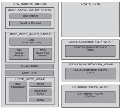
LPW system implements a convenient IP that consists of RF, AFE baseband, PHY and MAC. The IP is an 802.11 b/g/n complaint Wi-Fi solution with a focus on lowering active power consumption, leakage power consumption, ensuring low duty cycle operations and providing the lowest area.
Fig 1. LPW Block Diagram
Design Features of LPW:
The design features of LPW include the following:
Silicon Process Portable Design
Low Memory Bandwidth
Lower Power
Highly Programmable Architecture
High Performance
On this LPW design, the Scan Compression and Low Pin Count Test are implemented with the help of Tessentkompress tool described in below sections.
3. SCAN COMPRESSION USING EDT TECHNOLOGY
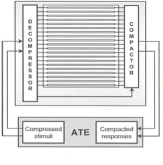
In this section Scan Compression is implemented on the above LPW design using EDT technology. Embedded Deterministic Testing (EDT) is the technology based on conventional, deterministic ATPG and uses necessary fault models to obtain high test coverage. EDT extends ATPG with improved compression of scan test data and a reduction in test time. EDT technology includes logic embedded on-chip, EDT-specific DRCs, and a deterministic pattern generation technique. The embedded logic consists of decompressor and compactor. The external scan channel inputs act as input and the internal scan chain inputs act as output to the decompressor. For a compactor the internal scan chain outputs act as inputs and the external scan channel outputs as outputs as shown in Fig. 2.
Fig 2. EDT Architecture
Thus, the EDT logic affects only the scan channel inputs and scan channel outputs, but not the functional path. The main objective of this EDT technology is to lower the tester memory usage drastically. Reducing the memory usage will leads to reduction in test time and increases the throughput of a tester while the test quality is maintained same. Before inserting EDT logic into design core, scan insertion has to be performed, as discussed in section 3.1.
3.1 Scan Insertion:
3.2 Decompressor:
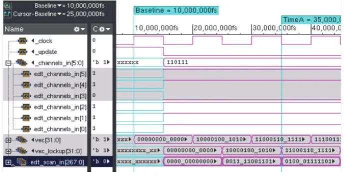
The second step is Scan compression inserting EDT logic which contains on-chip decompressor and Compactor as shown in Fig 2. The decompressor block contains a LFSR and a phase shifter. Since a decompressor is crucial to the effectiveness of EDT test data compression, it has to meet several requirements that include low linear dependency in its output sequences, high speed of operation, low silicon area, and high modularity of the design. A new structure, called a ring generator of 32-bit, is designed through Verilog code, the simulation wave forms of decompressor is shown in Fig 3, employed for this application. This ring generator is a precise form of a linear finite state machine. To perform on-chip decompression, the ring generator is further connected to a phase shifter. The purpose of phase shifter is to drive the 268 scan chains, and reduces the linear dependencies between the sequences entering the internal scan chains. A 32-bit LFSM is designed and the output of LFSR is given to phase shifter to feed the internal scan chains.
Fig 3. Observed Simulation waveform of decompressor
The simulation results of decompressor are shown below in Fig 3 where the values are generated for 268 internal scan input chains to feed into the core design.
3.3 Compactor:
The Compactor circuit consists of XOR tree. The Compactor input is from internal scan out chains or channels. Here the 268 internal scan out chains are compacted to 6 external channels in which the tester can see only these 6 channels from tester’s view. A Compactor is designed through a verilog code using ncverilog tool and the simulation waveform is shown below in Fig 4.
Fig 4. Observed Compactor Simulation waveforms
observed the factors, test time and test coverage. The industry-leading ATPG gives high quality scan test with low manufacturing test cost. To generate ATPG, Tessent TestKompress tool is used. The aim of ATPG is to create test sets that achieve high test coverage, where coverage is the ratio of total percentage of testable faults to the percentage of test pattern actually detects. The ATPG results are shown with test coverage, number of test patterns and fault coverage. The ATPG report is shown below in Table 1.
ATPG Reports:
The generated ATPG reports are shown in below Table.1 which defines the parameters, test coverage, compression ratio.
Scan cells: 133223 scan chains: 268
scan channels 6
Test coverage 98.93
Test patterns 2302
Fault coverage 94.5
Compression 44.5X
Table 1. ATPG Report generated in Testkompress tool
For this EDT logic inserted design, the LPCT is implemented to reduce test time and limited pin usage, discussed in next section.
4. LPCT WITH SCAN COMPRESSION
Inthis section Low Pin Count Test (LPCT) is implemented along with EDT compression. LPCT is a
technique which helps in reducing test cost by minimizing the usage of pins of a device at the time of testing. When LPCT is implemented, devices are tested easily on ATE at high reduced test cost, while meeting the pin limitation requirement of device. Combining LPCT with scan compression further enlarges the capabilities of testing. It deals with necessary fault models by using low-cost testers that are seriously pin- limited.
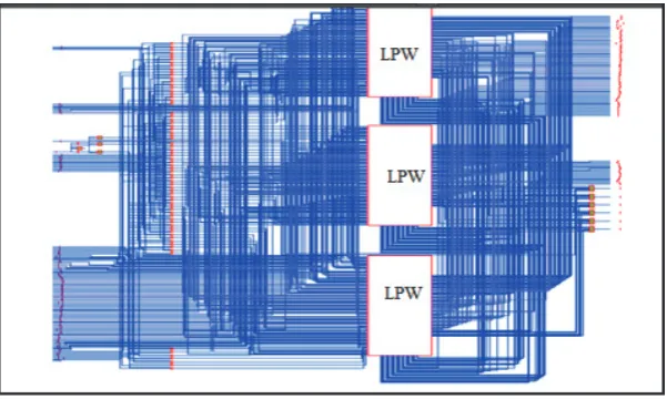
Fig 5. LPCT design with LPW Instantiation
In this paper the LPCT is implemented by a verilog software code, where the LPW design is instantiated thrice and those modules are controlled by a control signal 'sel' as shown in Fig 5. With the 2-bit control signal value one of the LPW module is selected. For sel = 2’b00 the first instantiation of LPW module is to be selected, similarly for 2’b01 and 2’b10 the second and third instantiated module will be selected respectively. So the test pins of one module is used to test the all instantiated modules, one at a time. Due to this the usage of pins is limited which reduces the test time and test cost.With this LPCT, the LPW module is selected with the control signal and ATPG is implemented to observe whether the required module instantiation is selected and scan chains been traced for the respective design.
5. RESULTS
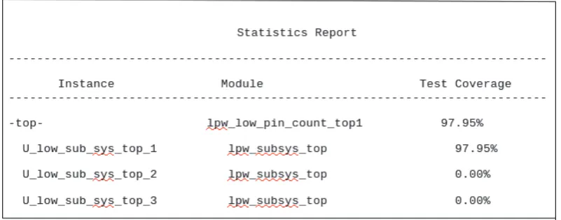
Combining LPCT with EDT compression, the required module can be tested by controlling with a control signal. The report of ATPG is shown below, selecting first instantiated module for testing. So only that particular module will run for test coverage, remaining modules will be disabled. So the common pins are shared to test multiple modules. The LPCT implementation is shown in below figure 6.
Fig 6. LPCT observed Reports with LPW 1 selected
From the above Fig.10, the first instantiation is selected and ATPG test coverage is done only for that particular module, remaining instantiations left uncovered, showing 0% test coverage. Similarly the other instantiations can also be selected one at a time for testing. With this LPCT mechanism, the design with hierarchical modules can be tested easily with the above test pins shown in Fig.6. So the test time will get reduced and pin usage for testing is limited, which leads to reduce in test cost.
5.1 Experimented Results:
In this sub-section, the results obtained after scan compression are compared by varying the number of scan chains, scan channels, scan cells as observed in below Tables 2, 3, and 4. These results show the decompressor efficiency and compactor capacity. For each input channel, the compression factor varies depending on the parameters scan compression and scan ration.
Compression ratio = Number of scan chains / Number of Scan channels (3)
From Eq. 3, the compression ratio is determined, which is the ratio of number of scan chains to the number of external scan channels. The below tables shows the compression levels with different scan chain length inserted in the design. For each scan chain length the compression level and size of decompressor differs. Assuming EDT external scan channels with 4 and 6 the comparison is observed in terms of compression, test coverage, test patterns.
Decompressor Efficiency:
Number of Scan chains = 268
Scan channels inputs Decompressor Size Compression Factor
4 32 67X
6 32 44X
8 32 33X
10 40 26X
12 48 22X
EDT channels =6
Chain length Scan chains Compression Factor Test Coverage Test patterns
2000 69 11.5X 98.14 2005
1500 92 15.75X 98.09 1902
1000 135 22.63X 97.87 1907
500 268 44.66X 97.95 2302
Table 3. Variation in Compression with change in chain length
EDT channels =4
Chain length Scan chains Compression
Factor Test Coverage Test patterns
2000 69 16.87X 98.06 2109
1500 92 22.74X 97.98 2111
1000 135 33.40X 97.99 2349
500 275 66.35X 97.93 3007
Table 4. Variation in Compression with change in chain length
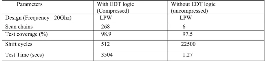
Parameters With EDT logic
(Compressed) Without EDT logic (uncompressed)
Design (Frequency =20Ghz) LPW LPW
Scan chains 268 6
Test coverage (%) 98.9 97.5
Shift cycles 512 22500
Test Time (secs) 3504 1.27
Scan cells : 133223
Table 5. Efficiency of Compressed and Un compressed mechanism
The data in Table 5. Shows the comparison between a compressed mechanism of design and uncompressed mode design reports, where it affects the parameters of test time majorly. The test time is calculated approximately from Eq. 1 and Eq.2.
6. Conclusion:
In this paper, the scan compression in performed using EDT technology, which plays a vital role in reducing manufacturing test cost. The logic inserted in EDT compression helps in providing a substantial reduction in scan test data volume and scan test time. Using this technology a high level of compression has been achieved. The more number of scan chains gives higher compression level. EDT methodology can be widely used in real time applications for its easy and simple design flow. In this technology high test quality is
guaranteed covers necessary fault models. As the design size for every eighteen months gets doubled, the
REFERENCES
[1] Ayari . B ; Kaminska.B, (1994) : A New Dynamic Test Vector Compaction for Automatic Test Pattern Generation, IEEE Trans. Computer-Aided Design of Integrated Circuits and Systems, vol. 13, no. 3, pp. 353-358.
[2] Hsu. F; Butler . K; J. Patel, (2001): A case study on the implementation of the Illinois scan architecture, ITC, pp.538-547.
[3] Hamzaoglu. L ; Patel . J, (2000): Reducing test application time for built-in self-test pattern generators, VLSI Test Symp., pp. 369-376.
[4] Rajski . J; Tyszer.J ; Zacharia . N, (1998) : Test data decompression for multiple scan designs with boundary scan, IEEE Trans. on Computer, vol. 47, pp. 1188-1200.
[5] Dorsch . R ; Wunderlich.H.J, (2001): Tailoring ATPG for embedded testing , ITC, pp. 530-537.
[6] Hellebrand .S ; Rajski . J; Tamick. S, (1995) : Built-in test for circuits with scan based on reseeding of multiple-polynomial linear feedback shift registers, IEEE Trans. on Cornputer, vol. 44, pp. 223-233.
[7] Litovski .V. B, (2010): Combining Low Pin Count Test with Scan Compression , IEEE Trans. Computer-Aided Design of Integrated Circuits and Systems, vol. 17, no. 10, pp. 1044-1051.