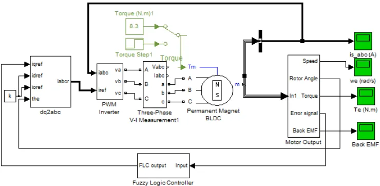
SPEED CONTROL OF PMBLDC DRIVE
WITH GATE CONTROL METHOD
USING CONVENTIONAL AND FUZZY
CONTROLLER
T.V.NARMADHA
St.Joseph’s College of Engineering, Department of EIE, Anna University Chennai, TamilNadu, India
T.THYAGARAJAN Director, Anna University Library,
Chennai,TamilNadu,India
Abstract
The paper presents simulation results of fuzzy logic and conventional proportional integral controller for the sensorless speed control of permanent magnet brushless dc (PMBLDC) motor using Gate control method. Although conventional PI controllers are widely used in the industry due to its simple control structure and ease of implementation, these controllers pose difficulties under the conditions of nonlinearity, load disturbances and parametric variations. Moreover PI controllers require precise linear mathematical models. In the paper, the performance of the permanent magnet brushless dc motor drive is examined with the aid of the fuzzy logic controller. The fuzzy logic controller shows improved performance compared to the conventional PI speed controller.The module of the Three Phase inverter system controlled Permanent magnet Brushless DC motor is simulated using PI and Fuzzy Logic Controller and implemented in closed loop model. . By simulation, the characteristics of the PMBLDCM system are investigated. THD analysis for the methods is presented. The simulation results indicate FLC has improved performance.
Key Words: Permanent Magnet Brushless DC Motor (PMBLDC), Proportional-Integral (PI), Fuzzy Logic, Pulse Width Modulation (PWM), THD, Performance measures.
1. Introduction:
Permanent Magnet Brushless Direct Current (PMBLDC) are becoming prominent as the demand for efficiency, precise speed and torque control, reliability and ruggedness increases. BLDC provide high efficiency and exemplary precision of control when compared to conventional motors. It has the best torque vs. weight or efficiency characteristics. They are used in military, grinding, aircraft, automotive applications, communications equipment etc [1]. The theory of brushless dc motors was proposed in 1962 by T.G. Wilson and P. H. Trickey. But the limitations in magnet and power switching have prevented them to bring into real life. In 1980, Powertec. Industrial Corporation started manufacturing them [2&3]. Brushless, as the name implies there are no brushes and commutators. In conventional motors, the switching of current in the armature coils is done using the combination of brushes and commutators whereas in the brushless, the commutation is performed with the help of electronic circuit, which reduces the mechanic losses and improves the efficiency. There are many other merits of brushless motors over the conventional motors.
• The brushless machines require less maintenance.
• Speed/torque characteristics are flat which enables operation at all speeds with rated load. Whereas brushed dc motors have moderately flat characteristics.
• The electric noise generation is low for brushless.
• Brushless motors have low rotor inertia which improves dynamic response. • They have higher speed range and output power to frame size ratio.
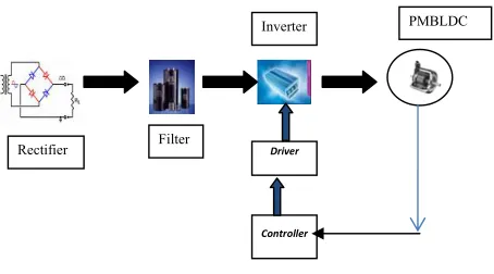
use of multi-variable control structure. Most of these controllers use mathematical models and are sensitive to parametric variations. Very few adaptive controllers have been practically employed in the control of electric drives due to their complexity and inferior performance. Fuzzy controllers[8-10] have proved to be successful in recent years. These controllers are inherently robust to load disturbances. Besides, fuzzy logic controllers can be easily implemented. The drive system considered here consists of fuzzy logic controller, conventional controller, PMBLDC motor and MOSFET based inverter. All these components are modelled and integrated for simulation. The simulation results shows Fuzzy logic controller has great improvement in both transient and steady state responses of the drive. Contrary to the PI controller, Fuzzy logic controller makes the PMBLDC drive more robust to load variations. The key feature of this scheme is to compensate the oscillations and harmonics in the response of the PMBLDC motor. Results of this scheme are compared based on transient analysis and performance measures such as IAE,ISE,THD and Three phase Instantaneous power. Fig1 describes the basic building blocks of the PMBLDC motor. Section I discusses the basis of three Phase inverter and mathematical modeling of PMBLDC motor and Inverter. Section II discusses simulation results of PI fed gate control PMBLDC motor drive. Section III presents the simulation results of Fuzzy control gate method fed PMBLDC motor drive. Conclusion and references are given at the end.
Fig 1 Basic Block diagram of PMBLDC Motor
1.1 VSI fed BLDC Motor with T-filter
It is possible to improve the input power factor by using a T-filter on the AC side. The AC line current can also be smoothened by using filters in the line just before the power electronic converter system. Inductors L1 and L2 basically increase source side inductance. They reduce higher order harmonics in the current. They also reduce outputvoltage ripple and current stresses on the rectifier diodes. The capacitor suppresses the high frequency harmonics and transients from being coupled to and from the source. The phase angle can be further reduced by using T-filter. The T-filter is designed such that XL is greater than Xc. Fig.2 shows the VSI fed
BLDC motor with T Filter. The input current waveform of VSI fed BLDC motor with input T filter is shown in Fig. 3.
Driver
Controller
Rectifier Filter
Fig 2. VSI fed BLDC Motor with T-filter
Fig. 3 Input Current waveform
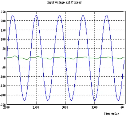
Fig. 4 Input voltage and current waveforms
The rotor speed of VSI fed BLDC motor with input T-filter is shown in Fig. 5. The simulated result shows that the rotor reaches the rated speed in 0.5 seconds.
Fig. 5 Rotor speed characteristic
Fig. 6 Frequency Spectrum of Input current
1.2 Three Phase Inverter
In three level inverter modeling, 120 degree conduction mode is employed. The gating signals given to the MOSFET are sequenced to every 60 degree interval. Each MOSFET conducts for a duration of 120 degrees. The MOSFET is used as a switch since it can operate high switching frequency. This feature is helpful in driving the motor with high current and low voltage conditions. The three phase inverter circuit is shown in Fig 7.
Fig 7. Three phase Inverter Circuit
1.3. Modelling Of PMBLDC Motor and Inverter
The PMBLDC motor is modeled in the stationary reference frame using 3-phase abc variables. The general volt -ampere equation for the circuit shown in the Fig.8 can be expressed as
van = Ria+ dΦa + ean (1) dt
vbn = Rib+ dΦb + ebn (2)
dt
vcn= Ric+ dΦc + ecn (3)
dt
where van, vbn and vcn are phase voltages and may be designed as
van= vao- vno, vbn= vbo - vnoand vcn = vco - vno. (4)
where vao, vbo, vco and vno are three phase and neutral voltages referred to the zero reference potential at the
mid- point of dc link as shown in the Fig.8
R is the resistance per phase of the stator winding, d - is the time differential operator and dt
ean,ebn and ecn are phase to neutral back emfs. The Φa, Φb and Φc are total flux linkage of phase windings a, b
and c respectively. These values can be expressed as:
Φa= Lsia - M(ib + ic) (5)
Φb = Lsib - M(ia + ic) (6)
Φc= Lsic - M(ia + ib) (7)
where Ls and M are the self and mutual inductance, respectively The PMBLDC motor has no neutral connection
and hence,
ia+ ib+ ic=0 (8)
Substituting equation (8) into equations (5), (6) and (7) the flux linkages are given as
Φa = ia(Ls + M)
Φb= ib (Ls + M)
Φc= ic(Ls + M) (9)
By substituting equation (9) in volt ampere equations (1) - (3) and rearranging these equations in a current derivative of state space form, we get
dia = 1 [van - Ria - ean] (10)
dt (Ls+M )
dib = 1 [vbn – Rib - ebn] (11)
dt (Ls+M )
dic = 1 [vcn – Ric – ecn] (12)
dt (Ls+M )
The developed electromagnetic torque may be expressed as
Te= [eania+ebnib+ecnic]/ ωr (13)
where ωr is the rotor speed in electrical rad/sec.
dt J
where P is the number of poles, TL is the load torque in N-m, B is the frictional co-efficient in N-ms/rad, and J is
the moment of inertia in kg-m2.
The derivative of the rotor position (θr ) in state space form is expressed as
dθr = ωr (15)
dt
The potential of the neutral point with respect to the zero potential (vno) is required to be considered in order to
avoid imbalance in the applied voltage and simulate the performance of the drive. This is obtained by substituting equation (8) in the volt-ampere equations (1) - (3) and adding them together. Hence,
vao +vbo +vco-3vno = R(ia+ ib+ ic)+(Ls + M) (dia/ dt+ dib/dt+ dic/dt)+(ean+ ebn+ec) (16)
Substituting equation (8) in equation (16) we get vao +vbo +vco-3vno = (ean + ebn+ecn)
Thus,
vno = [vao +vbo+vco - (ean+ ebn+ecn)] / 3 (17) The set of differential equations mentioned in equations (10), (11), (12), (14) and (15) define the model developed in terms of the variables ia, ib, ic, ωr, Te and time as an independent variable.
1.4 Modelling Of Back Emf Using Rotor Position
The per phase back emf in the PMBLDC motor is trapezoidal in nature and are the functions of the speed and rotor position angle (θr). The normalized function of back emfs are shown in Fig.9(a),9(b). From this,
the phase back emf ean can be expressed as:
ean = E 0° < θr <120° (18)
ean = (6E/π) (π - θr) - E 120° < θr < 180° (19)
ean = -E 180° < θr < 300° (20)
ean = (6E π /) (θr -2 π) + E 300° < θr < 360° (21)
where E = Kbω and ean can be described by E (22)
The back emf function of other two phases ebn and ecn are defined in similar way using E
1 1.1 1.2 1.3 1.4 1.5 1.6 1.7 1.8 1.9 2 x 10⁴ -150 -100 -50 0 50 100 150
Time in Seconds
(b)
Fig.9(a),(b) Phase back EMF of three Phase Voltage
For long period carried-based PWM methods were widely used in the most applications. The PWM modulation has been studied extensively in the last decade. Hence, the main objective of PWM over here to achieve following objective considerably
1. wide linear modulation range. 2. less switching loss.
3. less total harmonic distortion in the spectrum of switching waveform and 4. easy implementation and less computational calculations.
2.. Pu lse Width Modulation
2.1 Purpose of Pulse width modulation
The major contribution of the PWM in power system conversion/delivery as bulleted below:- • Control of inverter output voltages
•And reduction of Harmonic components
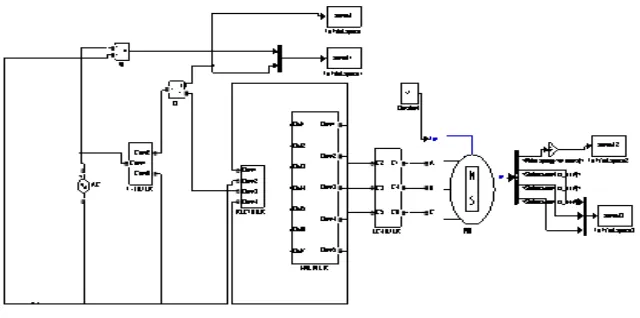
Fig.10 Closed loop speed control of PMBLDC motor using PI Controller
Fig 10 shows the simulink circuit for the closed loop speed control of PMBLDC motor using PI controller. The error between the set speed and the motor speed is obtained. Based on the error signal controller produces the iqref .Based on idref and iqref the stator phase currents iabcr is produced. By comparing this with iabc PWM signal is
ia=u(1)*cos(u(4)) + u(2)*sin(u(4)) + u(3) (23)
ib=u(1)*cos(u(4)-2*pi/3) + u(2)*sin(u(4)-2*pi/3) + u(3) (24)
ic=u(1)*cos(u(4)+2*pi/3) + u(2)*sin(u(4)+2*pi/3) + u(3). (25)
where u is the input variable.
2.2Fuzzy Logic Controller
The block diagram showing the implementation of the Fuzzy speed controller is illustrated in Figure 11. It includes four major blocks: knowledge base, fuzzification, inference mechanism, and defuzzification. The knowledge base is composed of a data and a rule base. The data base, consisting of input and output membership functions. The rule base is made of a set of linguistic rules relating the fuzzy input variables into the desired fuzzy control actions.
Fig 11 . Block Diagram of Fuzzy Logic
Rule base used in drive systems for a fuzzy logic controller consist of 49 linguistic rules, and gives the change of the output of fuzzy logic controller in terms of two inputs: the error (e) and change of error (de). The following fuzzy sets are used: NB negative Big, NM negative medium, NS negative small, ZR zero, PS positive small, PM positive medium and PB positive Big. For example, the first rule is:
IF e is NB and de is NB then controller output is NB The linguistic rules are in the form of IF-THEN rules and take form:
IF (e is X and de is Y) then (controller output is Z),
Where X, Y, Z are fuzzy subsets for the universe of discourse of the error, change of error and change of the controller output .For example, X can denote the subset NEGATIVE BIG of the error etc.
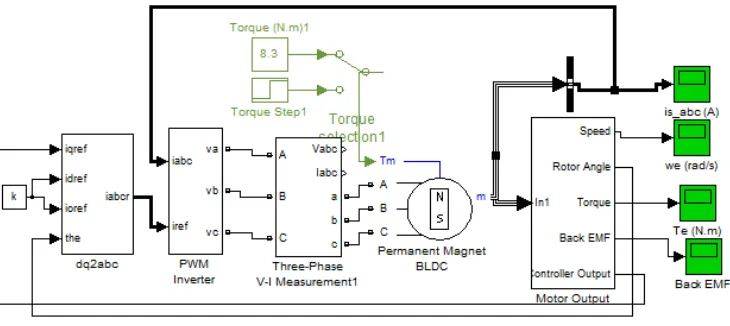
Fig.12 Closed loop speed control of PMBLDC motor using Fuzzy Logic Controller
Fig12. shows the simulink circuit for the closed loop speed control of PMBLDC motor using Fuzzy Logic controller. The error between the set speed and the motor speed is obtained .The error and change in error is taken as FLC input. Fuzzy control is based on fuzzy logic, which provides an efficient method to handle inexact information as a basis of reasoning. With fuzzy logic it is possible to convert knowledge, which is expressed in an uncertain form, to an exact algorithm. In fuzzy control, the controller can be represented with linguistic if-then rules. The interpretation of the controller is fuzzy but the controller is processing exact input-data and is producing exact output-data in a deterministic way.
Fig. 13 Rotor Speed in rpm
Fig. 14 Controller Voltage
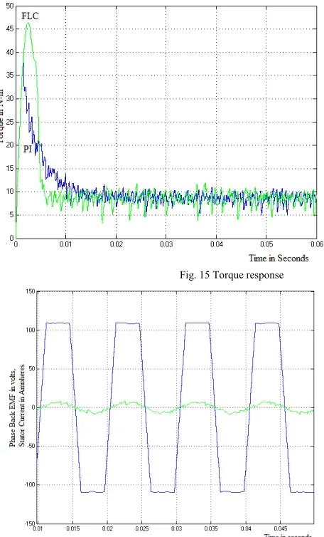
Fig.15 shows the torque response of fuzzy and PI controller. While using Fuzzy logic controller torque climbs to nearly 47 N-m when the motor starts and stabilizes rapidly when the motor reaches the reference value. The nominal torque is applied at t = 0.1 second and the controller react rapidly to produce the required electric torque. By using PI controller the torque climbs only upto 37.5N-m when the motor starts and takes larger time to stabilize compared to fuzzy logiccontroller.
Fig. 15 Torque response
Fig16 shows the phase back emf and stator phase current response. The phase back emf is in phase with stator phase current. To get maximum efficiency from the motor, the commutation should take place when the current in a winding is in phase with the back-EMF in the same winding. The best efficiency is obtained when the 2 signals are in phase as shown in Fig16. Effectively, as the useful electrical power (mechanical power) of the motor is given by the equation Pe=E*I, the product will be maximum when the Back-EMF and the current are in phase.
Table1: Performance Analysis
Performance Measures
PI FLC
THD in Phase current 3.123 1.434
RMS 4.625 4.886 Power 1642 2240
IAE 69.74 11.55 ISE 1500 133.5
Ts 0.133 sec 0.006 sec
Table 1. shows the comparison of performance analysis of PI and FLC controller using gate control method. It is clear that the FLC has improved performance in all aspects compared to conventional PI controller.
5. Conclusion
A PI and Fuzzy logic controller is used to control the firing angle of an inverter to control the speed of PMBLDC motor drive. The modelling and simulation of the complete drive system is described in the paper. A performance comparison between the fuzzy controller and the conventional PI controller has been carried out by simulation. The results have shown that fuzzy controller is robust to external load disturbances. The power transferred to load is increased by 1.3 times using Fuzzy logic controller compared with PI controller. The performance of the PMBLDCM drive with reference to both the steady state and the dynamic conditions is improved with the application of the Fuzzy logic controller.
Reference:
[1] http://www.electricmotors.machinedesign.com/guiEdits/Content/bdeee3/bdeee3_3.aspx
[2] Large Brushless Drive Systems: Is there one in your future? – http://powertecmotors.com/a0201el.pdf
[3] C.L.PuttaSwamy, B.Singh and B.P.Singh, “Investigations on Dynamic behavior of Permanent Magnet Brushless DC [4] motor drive,” Journal of Electrical Machines and Power Systems”, Vol.23, No.6, Nov/Dec 1995, pp. 689-701. [5] P C Kluk, C K Lee, “Efficient modeling for a brushless DC motor drives”, IEEE Conference on Industrial Electronics [6] (IECON), 1994.
[7] C.C. Lee,” Fuzzy logic in control systems: Fuzzy logic control part1 & part2”, IEEE Trans. Syst., Man, Cybern, [8] vol.20, no.2, pp. 404-435, Mar./Apr.1990.
[9] N.Li, “Design of a Hybrid Fuzzy logic Proportional plus conventional Integral Derivative Controller”, IEEE Transactions on Industry Applications, Vol. 27, No.4, November 1998, pp. 449-463.
[10] K. H. Kim and M. J. Youn, “Performance comparison of PWM inverter and variable DC link inverter schemes for high-speed sensorless control of BLDC motor”, Electronics Letters, Vol. 38, No. 21, pp. 1194-1295, Oct. 2002.
[11] E.Cerrupto, A.Consoli, A. Raciti, “Fuzzy Adaptive vector control of Induction motor drives”, IEEE Transactions of Power Electronics, Vol.12, No.6, Nov 1997, pp.1028-1040.
[12] J.E.Silva Neto and H.L.Huy, “A Fuzzy Controller with a Fuzzy Adaptive mechanism for the speed control of a PMSM”, IEEE Conference on Industrial Electronics 1997, pp. 995-1000.