http://www.sciencepublishinggroup.com/j/ajetm doi: 10.11648/j.ajetm.20200501.12
ISSN: 2575-1948 (Print); ISSN: 2575-1441 (Online)
Comprehensive Research on Development of the New
Blade Bits Design
Boris Vladimirovich Fedorov
1, Gulzhan Abdullaevna Kudaikulova
2, *,
Boranbay Tovbasarovich Ratov
3, Akniyet Rabbimuly Bayboz
11Department of Geology and Oil & Gas, Satpaev University, Almaty, Kazakhstan 2Limited Liability Partnership “Burmash”, Almaty, Kazakhstan
3
Institute of Geology and Oil & Gas, Caspian University, Almaty, Kazakhstan
Email address:
*Corresponding author
To cite this article:
Boris Vladimirovich Fedorov, Gulzhan Abdullaevna Kudaikulova, Boranbay Tovbasarovich Ratov, Akniyet Rabbimuly Bayboz.
Comprehensive Research on Development of the New Blade Bits Design. American Journal of Engineering and Technology Management. Vol. 5, No. 1, 2020, pp. 12-17. doi: 10.11648/j.ajetm.20200501.12
Received: January 8, 2020; Accepted: January 31, 2020; Published: February 20, 2020
Abstract:
This article presents data on the development of the peak-shaped blade bit with an increased productivity, resistance and reduced energy capacity used at drilling wells in soft rocks and partially in rocks of medium hardness. In order to achieve this goal a comprehensive research with the theoretical, design and development and experimental works were carried out. It is shown that the distribution of the axial load on the radial cutters of the bit is uneven, which is a reason for such complication as the "hanging" of the bit over the bottom of the well. As a result of the research works, the peak-shaped blade bit was developed and patented, which increases drilling productivity by 24%.Keywords:
Blade Bit, Peak-shaped Blade Bit, Core Destruction, Soft Rocks, Removal of Cutters, Drilling Mud, Core Breaker1. Introduction
About 25% of the world's uranium resources are concentrated in Kazakhstan, and about 70% of them are associated with aquifers and are suitable for mining by a fairly effective and safe method of downhole leaching. The implementation of the industry development program allowed Kazakhstan to take first place in the world in uranium mining, which in 2010 reached 15,000 tons [1, 2]. This achievement would not be impossible without improving the equipment and technology for the construction and operation of geotechnological wells, which have much in common with the technology of creating hydrogeological wells.
As a rule, in geological sections of uranium deposits and groundwater deposits the soft rocks are involved, and rocks of medium hardness are less frequently used. It allows to use the peak-shaped blade bits equipped with carbide cutters and
more recently, PDC cutters when drilling wells.
At the same time, the peak-shaped blade bits currently used for drilling do not meet modern requirements due to the complications during drilling (regular “hanging” of the bit over the bottom of the wells), high energy capacity of destruction, insufficient tool life and productivity, as well as the significant cost of 1 m of drilling wells.
Due to the increasing volume of geotechnological well drilling, the creation and implementation of drilling tools of increased persistence, lower energy capacity and higher productivity is a very important problem, the solution of which will increase the efficiency of drilling operations.
2. Methods
The following methods of research are used in this article: 1.The theoretical methodology of the determination actual
along the radial blades of bit;
2.Literary analysis of the reasons for the “hanging” of blade bits above the central part of the well bottom; 3.Experimental and practice researches to create of the
new peak-shaped blade bit sample without effect of “hanging” of blade bits above the central part of the well bottom;;
4.Mathematical calculation of the expected economic effect using the new blade bit design.
3. Discussion (Part 1)
One of the problems complicating the technology of drilling with blade bits operating in the cutting mode is the so-called “hanging” of the bit over the central part of the well bottom. Visually, this phenomenon comprises the fact that for some time a rotating tool stops deepening the bottom, then the rock is slowly crushed along the axis of the bit, drilling recommences until the next “hanging” etc. Such phenomenon was observed multiple times when drilling oil and gas wells with blade bits reinforced with PDC cutting plates [3]. In this work, an abrupt decrease of the destruction of bottom was noted as it approaches the axis of the rotating bit. To rectify such complications, Smith Bits (subsidiary of Schlumberger) proposed a bit with a cone-shaped solid body with diamond spraying in the axial end area to destroy the rock in the central part of the bottom. This technology has shown sufficient efficiency when drilling harder rocks other than uranium complex rocks.
The research analysis of soft and medium hard rock drilling technology has demonstrated that there are no works to reveal the occurrence of complication associated with the regular hanging of a blade bit.
To solve this problem we used the comprehensive research method including theoretical, development and experimental works.
To clarify the reasons for "hanging" of the blade bits during drilling, the well-known theories of rotary drilling with cutting tools were analyzed [4-10]. The drilling theory developed by the famous scientist V. S. Vladislavlev [9] gives an explanation for this phenomenon.
The main principle of this theory is that the depth of penetration of the cutter during rotation around the circumference is proportional to the path travelled by this cutter. This means that the cutter during rotation and deepening of the bottom moves in a spiral, the tangent of the angle of inclination α is [9]:
tgα = 2q/Aδ, (1)
q – the intensity of the vertical load, q = Q / kb (Q – the axial load on the tool, K– the number of cutters overlapping the face width in radius, b – the face width in radius); A –
rigidity of the pair "cutter-rock"; = (E – the elastic modulus of the rock being destroyed; µ– the Poisson's ratio of the rock); δ – the width of the end of cutter in the direction of its movement.
From dependence (1), one can easily obtain the formula for the bottom well h per one turn-over of the bit, taking into account the influence of the constrained working conditions of the tool in the well, as well as the formula for calculating the real load Qi, which reduces the assigned load Q due to the friction force T acting by front edge of the cutter and directed upwards. The corresponding formulas for calculating the above values are given in [9] and are given below.
Since at a complete turn-over of the cutter during rotation around a circle of radius R1, = , then the recess h
into the bottom of well for one turn-over of bit, taking into account formula (1) and its provisions, will be equal to:
ℎ = 2 ( )
Ɣ , (2)
where Ɣ – coefficient taking into account the constrained working conditions of the cutters in the well. It is assumed that Ɣ = 1.38 [9].
Mechanical drilling speed:
= ℎ , (3) where n is the bit rotation frequency, 1/s.
When the cutter moves along the bottom, overcoming the resistance of the rock, it acts with the front face on the wall of the rock with force P equal to
P = ! " b H, (4) where ! " – rock tensile strength, b – groove width, H - its depth equal to:
# = ℎ/%, (5) On the front edge of the cutter, the force P causes a friction force T directed upward and counteracting the vertical load
Q:
& = '(, (6) where f – coefficient of friction at the contact "cutter-rock". f
= 0.1-0.4; [9]
Thus, the true value of the axial load Qtwill be:
)*= ) − &, (7)
From (7) it shows that the required axial load on the bit assigned on the surface must be increased by the force T
taking into account (4-6) to obtain the desired effect
Т = -*. /
0 (8)
The given dependences (1-8) make it possible to obtain the distribution of loads along the radius of the bit blades and find out the reason for the regular “hanging” of bit.
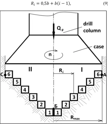
When drilling, an axial static force Q and a torque are applied to the blade bit, transforming into the frequency “n” of rotation of the tool. (Figure 1) Mentally divide each blade of bit along its length Rmax by the required number of equal
In operation, at each turn-over of the bit, different sections will move around a circle whose length is proportional to the radius. The maximum path will be made by the cutters located at the outer edge of the bit: cutters located near the center run a path several times smaller. The path of the cutter located on the axis of rotation of the bit will be zero.
Assume that the peak-shaped blade bit has a diameter D,
the number of blades is m, and K of the cutting elements i is placed on each blade, counting from the axis of rotation (Figure 1). Then the distance from an arbitrary radius Ri of
the middle of the “i” element to the axis of rotation is determined by the formula:
= 0,53 4 3 5 + 1 , (9)
Figure 1. Drilling scheme with using peak-shaped blade bit.
1,2,3…6 – cutters; Ri – rotation radius of i-th cutter; Rmax – maximum rotation radius; I, II – edges (blades).
Where b – width of the “i” cutting element along the blade from the axis of rotation of the peak-shaped blade bit. With equality along the length of the cutting elements b = D/2K.
If the total load on the bit during drilling is ) , and the number of blades is m, then we can write
) 7 ∑ ) (10) Using formulas (8-16) given in [9], the following formula is obtained for determining the axial load for any cutter located on the cutting edge of the blade bit:
) 9; <.>: 4Д -*./0 @ # (11)
where the depth h of the removed rock layer per turn-over of the bit can be expressed;
AB
C , (12)
where ʋm – the drilling speed, n – bit rotation frequency (1/s).
The formula analysis (11) shows that the first term in brackets depends on the position of the cutting element on the blades, i.e. from its radius of rotation Ri, determined by the formula (9). The second term is independent of Ri.
4. Results (for Part 1)
Let us explain the distribution of loads Qi along the radius of the blade using a specific example with the following initial data: D = 0.22m, σstr = 4 ⋅107 Pа, f = 0.4, К = 6, Е = 6
⋅1010 Pа, δ = 0.0005m, µ = 0.3, ʋm= 18m/h = 0.005 m/s, Ɣ =
1.38, n = 100 r/min = 1.674 r/s, m = 4.
Calculation of the distribution of axial load on the blades of bit is carried out in the following sequence:
1. Depth h of the removed rock layer is determined for one turn-over of bit (formula 12):
h = .DE; F ; <.<<> = 0.00075
2. Width b of each cutter is determined:
3 2 F 6 0.01833 м0.22
3. Radius Ri is determined from the middle of the “i” cutter
to the axis of rotation (formula 9) for six values i = 1, 2, 3, 4, 5, 6.
R1= 0.00092 м, R2= 0.0028 м, R3= 0.0046 м, R4= 0.0064 м,
R5 =0.0082,
R6= 0.101 м.
4. Load on one blade of the bit Qi and the total load on
four blades of Q* (formula 11) are determined
i = 1, R1= 0.00092 м, Q1 = 6.3кL, Q*= 6.3кN ⋅ 4 = 25.2 кN
i = 2, R2= 0.0028 м, Q2= 3.27 кN, Q *
= 3.27 ⋅ 4 = 13.08 кN. Similar calculations are given for i = 3, 4, 5, 6.
The calculation results are shown in Table 1 and Figure 2.
Table 1. Axial load distribution for one (Qi ) and four blades (Q*) along the radius of the peak-shaped blade bit.
i 1 2 3 4 5 6
Ri, mm 9,20 28,00 46,00 64,00 82,00 101,00
Qi, кN, load on “i” blade of bit 6,3 3,27 1,5 1,12 0,92 0,80
Figure 2. Dependence of the load Q* acting on the four blades of a peak-shaped blade bit, depending on the radius of rotation Ri of the cutting elements.
5. Conclusions (for Part 1)
The analysis demonstrates that the minimum load during the destruction of the well bottom at a given speed is on the periphery of the peak-shaped bit at Rmax = 110 mm, where
Q* is only 3 kN. The axial load along the axis of the bit, on the contrary, reaches a huge value, increasing up to 25 kN, i.e. more than 8 times. When drilling different sections of the blades move around circles whose length is proportional to the radii of their rotation. The maximum way will be made by the cutters located not on the edges of the bit blades, but on the axis of the bit rotation and it will be zero. But since we are talking about a single whole blade with blades, then deepening for all its sections can be the same. An equal deepening for cutters running a different way is ensured by redistributing the axial load acting on the peak-shaped blade bit, and therefore it grows on the cutting edge of the blade in the direction of the rotation axis, as if compensating for a decrease in the way of the cutters. As a result, there is a stop, “hanging” of the peak-shaped blade bit, which will take some time to crush rock in central part of the bottom well, which complicates the drilling process and reduces its productivity.
Returning to the analysis of data in Table 1, we could conclude that it is necessary to eliminate the excessive load in the area adjacent to the axis of rotation of the peak-shaped blade bit. This can be done in a simple way, eliminating several near-axis steps of the blades with cutters. The resulting soft rock core should be washed out with a jet of drilling mud, and the harder rock core should be destroyed with a mechanical core breaker. This will significantly reduce the total load on the bottom of well, reduce the energy consumption of drilling, eliminate the “hanging” and increase the resistance of peak-shaped blade bit.
6. Discussion (Part 2)
The studies as per Part 1 determined direction of the experimental design work to create a more efficient peak-shaped blade bit.
It is known that the peak-shaped blade bits have been used effectively for a long time when drilling soft and partially medium hard rocks [8]. In Kazakhstan, the widespread use of peak-shaped blade bit is associated with the drilling of geotechnological wells used for the extraction of uranium raw materials [1]. The depth of the constructed wells reaches 600-700 m, and the rocks belong to the II-V category for drillability. The widespread use of peak-shaped blade bit in these conditions is explained by a low category of rocks for drillability, a sufficiently high drilling productivity (10-13 m / h), simplicity of design and low cost of the tools. The most widespread was the four-blade peak-shaped bit of Volkovgeologiya JSC, the design of which is shown in Figure 3.
Figure 3. Four-blade hydraulic monitor peak-shaped blade bit design.
JSC "Volkovgeology"
1 - case, 2 - lock thread, 3 - monitor holes, 4 - blades, 5 - carbide cutters.
The process of destruction bottom of well comprises the combined effect of carbide cutters on it and the action of high-speed jets of drilling mud ejected from hydraulic nozzles 3 (Figure 3).
Therefore, the creation of a new peak-shaped blade bit should be based on the recommendations of theoretical studies of Part 1, which refer to the above problems of the applied peak-shaped blade bits.
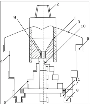
The above recommendations are implemented in the design of our patented peak-shaped blade bit [9] (Figure 4).
Figure 4. Peak-shaped blade bit (patent RK No. 33077 (104033)).
1 – case, 2 – thread, 3 – blade, 4 - outer ledge, 5 - internal ledge, 6 - cutter outer ledge, 7 - a cutter of an internal ledge, 8 - cutter cut, 9 - hydraulic nozzle, 10 – core breaker, 11 - ring stiffness.
Design of the bit is characterized with the presence on blades of internal ledges 5 with cutters 7, ending with a core breaker 10 and a ring 11 welded to the lower part of the blades, connecting the bit into a single rigid structure. The lowermost part of the blades is equipped with cut-in cutters
8.
Operation of the peak-shaped blade bit is as follows. After the drill column is lowered to the bottom, the axial load and
rotation are applied to the peak-shaped blade bit, using the drilling mud pump, mud is supplied to the bottom under pressure. The peak-shaped blade bit rotating and pressed against the bottom by means of the cutter 8 forms initially an annular bottom, the outer diameter of which expands to the required diameter of the well as the well deepens due to the outer reinforced ledges of 4 blades. At the same time, the core formed decreases in diameter due to its destruction by the cutters of the inner ledges of the 5 blades.
The uppermost tier contains a core breaker, in which one of the cutters of the opposite blades is mounted closer to the axis in rotation than the second. As a result, the core reduced in diameter will experience bending stresses, which will certainly lead to its breaking.
To obtain an objective information about the performance characteristics of the patented peak-shaped blade bit, its reliability and durability, two samples of the mentioned blade bit were made, and the relevant laboratory tests were carried out together with the serial peak-shaped blade bit designed by Volkovgeologiya JSC. Drilling with both tools was carried out in cement blocks with dimensions of 700 x 800 x1000 mm. The composition of the blocks is as follows: a mixture of cement M400 (30%), sand (30%) and water (40%). Setting and hardening of blocks for 2 weeks. Given the number of blocks (5 pieces), a total of 15 points have been outlined for drilling wells with a depth of 700 mm for each tested peak-shaped blade bit.
URB-2A-2 as a self-propelled drilling rig was used for drilling, equipped with a movable rotator and a drilling mud pump NB-32.
Test drilling was carried out in the following sequence: initially all 15 wells were drilled using the standard peak-shaped blade bit designed by JSC "Volkovgeologiya". Then the same tests were carried out by the PK-1 patented peak-shaped blade bit (core peak-peak-shaped bit, first model).
Parameters of the technological mode were the same when using both peak-shaped blade bits with the following values: bit rotation frequency, rpm - 325; axial load, kN - 20; consumption of drilling mud (water), l / s - 5.
During pilot drilling, the drilling time of each well with a depth of 0.7 m (in seconds) was recorded. The results of comparative tests of drill bits are shown in Table 2.
Table 2. Results of comparative pilot tests of peak-shaped blade bit.
Type of peak-shaped blade bit
Well numbers
1 2 3 4 6 7 8 9 10 11 12 13 14 15 Drilling time of
each well., Sec
Designed by PC - 1 36 34 39 31 36 34 37 38 32 35 36 35 38 36
Standard 46 45 44 40 42 43 46 47 48 44 44 43 42 44
As shown in Table 2 it demonstrates that the patented peak-shaped blade bit PK-1 has a steady, stable higher drilling performance than the standard peak-shaped blade bit by Volkovgeologiya JSC. Examination of the armament of both peak-shaped blade bits showed that carbide cutters were not blunt, which was explained by the low hardness and
abrasiveness of the cement stone.
Table 3. Drilling speeds of 15 wells with comparable peak-shaped blade bits.
peak-shaped
blade bit Drilling time of each well, seconds Average speeds
Х 70 74.1 64.6 81.3 66.3 70 74.1 68.1 66.3 78.7 72 70 72 66.3 70 XСР=70.6 m/h
Y 54.8 56 57.3 63 60 58.6 54.8 53.6 56 52.5 57.3 57.3 58.6 60 57.3 YСР=57 m/h
Difference in average velocities was determined:
∆ =XСР - YСР = 70.6 – 57 = 13.6 m / h.
Variances of the quantities X and Y are determined: Dx = 22.8, Dy = 7.02.
The actual Students criterion is determined:
tα = 13.6 / M 22.08 / 15 + 7.02 / 15) = 9.78 Degrees of freedom are determined f1 = n1 + n2 – 2 = 15 +
15 – 2 = 28. (n is the number of drilled wells).
According to table 2 of [11], the tabular value of the criterion tα is determined, which in this case with the probability P = 0.9 and f1 = 28 is equal to tαТ = 1.701.
Since tα > tαТ (9.78 > 1.701), the difference in the two
samples is very significant.
Thus, it is shown that the developed patented peak-shaped blade bit PK-1 showed a productivity of (70.6 - 57) / 57 x 100% = 24% more than the used standard peak-shaped blade bit.
This is confirmed by preliminary production tests of new peak-shaped blade bit during drilling of two wells, which resulted in increase of tool resistance by 20% (360 m drilled by the new peak-shaped blade bit against 280 m using known bit designs).
7. Conclusion
1. From the standpoint of the theory of drilling Vladislavlev the phenomenon of “hanging” of the blade bit under the central frequency of the bottom is explained. The mentioned phenomenon comprises an extremely uneven distribution of the axial load on the cutters located on the radial blades of the bit, and most of it acts on the near-axial region of the cutters with zero deepening of the bottom.
2. Analysis of the distribution of the external load on the cutters located on the radial blades of the bit, led to the idea of eliminating the cutters located near the axis of rotation of the bit, and destroy the resulting core with drilling mud or mechanical core breaker. The mentioned idea is implemented in the design of the peak-shaped blade bit, for which a patent of the Republic of Kazakhstan was obtained.
3. It is required to conduct preliminary production tests of
the new peak-shaped blade and analyze results.
4. The obtained research results can be used to create lobed peak-shaped bits equipped with diamond - carbide cutters PDC for drilling oil and gas wells.
References
[1] Rakishev B. R., Fedorov B. V. Technique and technology of the construction of geotechnological wells. Almaty, KazNTU, 2013, 355с.
[2] Sushko S. M., Kasenov A. K., Musanov A. M., Begun A. D. Drilling and equipment of the geotechnological wells. Almaty, KazNTU, 2010, 483 P.
[3] Dick Gismin. Technological support for the improvement of drill bits. Offshore (Russia), №1 (1) September 2013, pp. 42-45.
[4] Balaba V. I., Bekbulatov I. K., Vyshegorodtseva G. I. and others. Drilling rock destroying tool. M: Gubkin RSU Oil and Gas, 2013, 245 P.
[5] Abaturov V. G. Physical-mechanical properties of rocks and drilling rock destroying tool. Tyumen: Publ. Oil and Gas University, 2008, 238 С.
[6] Gandjumyan R. A., Kalinin A. G., Serdyuk N. I. Calculations in drilling. Handbook. M: RGGRU, 2007, 664 P.
[7] Fedorov B. V., Huzina L. B., Ratov B. T., Sharauova A. B. Modeling of process of deepening wells with RDS bits. Almaty. Oil and Gas, 2017, N. 4. P. 77-85.
[8] Popov A. N., Spivak A. I., Akbulatov T. O. and others. The technology of drilling oil and gas wells. M: Nedra, 2004, 509 P.
[9] Biletskiy M. T., Ratov B. T., Baiboz A. R. The use of computer user programs for the analysis of theoretical models of rock destruction during drilling. Science News of Kazakhstan, N. 3, 2018, p. 80-93.
[10] Afanasiev I. S., Ponomarev P. P. and others. Guide to drilling exploration wells. L: VITR, 2000, 580 С.
[11] Biletskiy M. T., Ratov B. T., Bayboz A. R. Patent for the invention of the Republic of Kazakhstan. № 33077 (104033). Drill bit type peak-shaped. 10.09.2018, Bull. № 34.