Online version is available on http://research.guilan.ac.ir/cmce Comp. Meth. Civil Eng., Vol. 3, 1 (2012) 15-34
©Copyright by the University of Guilan, Printed in I.R. Iran
Buckling and failure characteristics of slender web I-column girders under
interactive compression and shear
M.M. Alinia∗, A. Dibaie
Department of Civil Engineering, Amirkabir University of Technology, Tehran, Iran. Received 18 November 2011; accepted 23 April 2012
Abstract
Geometric and material nonlinear behavior of slender webs in I-column girders having stocky flanges under the action of combined lateral and axial loads is investigated. Interaction curves corresponding to the application of compressive and shear loads at buckling and ultimate stages for both web plates and column sections are plotted. In addition, the effects of flange and web slenderness ratios on the behavior of columns are studied. Results show that the effect of compressive loads on decreasing shear buckling and ultimate capacities of slender web plates is more than the effect of shear on the relative axial capacities. In the case of dominant compressive loading, the increase of shear force does not reduce the ultimate axial capacity of web plates.
Keywords: Web plate; Interaction; Compression; Shear.
1. Introduction
Plate assembled columns and girders can undergo various failure modes. These include flexural buckling, torsional buckling, flexural-torsional buckling, flange or web local buckling, full yielding of section or any combination of the above. In this study, the local buckling failure mode of web plates is investigated. For this purpose, web plates are presumed to be slender, while flange plates are assumed stocky. Therefore, the objective of this research is intended to investigate the buckling and postbuckling behavior of web plates in I-column girders under the action of combined axial compressive and lateral shear loadings. Peripheral columns are commonly subjected to considerable simultaneous axial and lateral forces.
Theoretical investigations on the buckling and postbuckling behavior of thin plates have been extensively carried out over the past decades [1-2]. The postbuckling behavior of web plates in shear was first discussed in 1886 by Wilson [3]. The theory of uniform diagonal tension for very thin web plates utilized in aeronautical engineering was developed by
∗
Corresponding author.
424 Hafez Ave. Tehran 15875-4413. Iran Tel: +9821 6454 3034, Fax: +9821 6641 4213
E-mail address: [email protected]; [email protected]
CMCE
Wagner in 1931 [4]. A fundamental theoretical work on the buckling phenomena of slender plates under pure shear was carried out in 1947 [5]. Basler [6] and Porter [7] proposed different shear failure theories for plate girders [8]. Hoglund [9] developed the rotational stress field theory for plate girders. His theory was later incorporated in Eurocode 3 [10]. More recently, the present second author and his colleagues have investigated different aspects of thin plates under shear [8, 11-19].
The buckling and postbuckling behaviors of thin plates in compression have also been widely investigated by many researchers [20-25]. In addition, the behavior of I-slender section columns under compression has been studied by a number of investigators [26-29]. Lindstorm [26] tested mild steel I-section columns composed of slender webs and stocky flanges. Davids and Hancock [27-28] carried out tests on short and long I-section columns fabricated by welding high tensile steel plates. The short length specimens failed mainly by yielding in the post local buckling domain. Salem et al. [29], worked on establishing series of interaction design curves for slender I-sections in compression using the gross properties and taking into account the interaction of the width/thickness ratio of plate elements comprising the cross sections.
The buckling and postbuckling behavior of detached thin plates in combined shear and compression have also been investigated by a number of authors, including Stowell and Schwartz [30], Harding et al. [31] and Zaras et al. [32]. Since detached plates having conventional boundary conditions cannot accurately represent the behavior of web plates [8], complete columns under various loading condition should be considered in the analyses.
In the present paper, the buckling and postbuckling behaviors of short and medium height columns having slender webs and stocky flanges subjected to interactive compression and shear are evaluated and the results are compared to the available theories. In addition, the effects of flange and web slenderness ratios on the behavior of such girders are investigated. Finally, axial-lateral interaction curves for I-column girders at both buckling and ultimate stages are presented.
2. Method of study
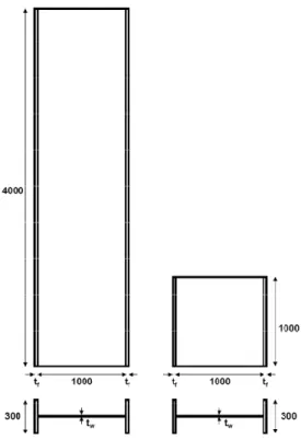
Two typical plated columns, one 1 m height and the other 4 m, both having similar section properties as depicted in Figure 1, are considered. The web and flange widths are assumed to be 1000 mm and 300 mm, respectively. To start with, the web and flange plate thicknesses,
w
t and tf, are presumed to be 5 mm and 30 mm, respectively. However, during the parametric studies for flange and web slenderness ratios, these thicknesses are varied accordingly. The selection of slender webs and stocky flange thicknesses are in accordance with the limits defined in the AISC 360 [33].
The ABAQUS finite element package [34] is utilized in incremental nonlinear large displacements pushover analyses. Both geometrical and material nonlinearities are considered in the studies. The nonlinear pushover analyses are carried out by utilizing the modified Riks method, allowing for both stiffness hardening and softening of plated structures.
Figure 1. Geometrical properties of columns. All dimensions are in mm.
The structural elements are modeled via the four-node reduced integrated doubly curved shell element S4R. This element accounts for finite membrane strains and large rotations. The S4R element has three translational and three rotational degrees of freedom at each node. It is based on an isoparametric formulation and uses one integration point on its mid-surface to form the element internal force vector. The reduced integrated formulation is selected to provide accurate results as well as to reduce computer CPU time.
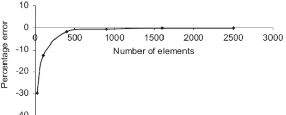
A convergence study was primarily carried out to obtain the sufficient number of mesh elements to allow for the development of buckling modes and displacements in web plates. For this purpose, a typical plate under pure in-plane shear was meshed into different numbers of elements; and their shear buckling stresses were compared to the classical equation (1).
(1) 2 2 2 ) 1 (
12 ⎟⎠
⎞ ⎜ ⎝ ⎛ − = b t E K w cr ν π τ
K is the shear buckling coefficient which depends on boundary conditions and aspect ratio of plates; and b is the web width. Figure 2 shows the variation of percentage errors obtained by comparing the FE results to the theoretical value for different number of incorporated elements. Based on this figure, the model with 1600 elements produced results that were very close to the theory within a reasonable running time; and was hence incorporated in the analyses.
Figure 2. Convergence study for the number of mesh elements.
Mild steel material with an initial elastic modulus of E=200GPa, normal yield stress of 240
y MPa
σ = and Poisson’s ratio of ν =0.3 were used throughout this study. The material was assumed elastic perfectly plastic; and the von Mises yield surface was utilized as the yield criterion.
To simulate fixed column-base plate connection, the lowest nodes of columns were restrained in all directions. A rigid plate was placed at the top end of columns to provide uniform end displacements. Both axial and lateral loadings were applied via this rigid plate.
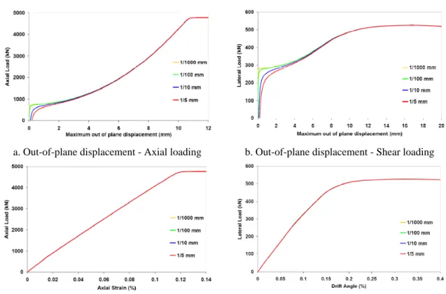
The governing failure mode in the typical girders considered in this research was presumed to be initiated by the web local buckling. Therefore, in the nonlinear analyses, small initial imperfections proportional to the lowest elastic buckling eigenbuckling mode shapes were introduced to the web plates. Initial imperfection can arise from various sources such as fabrication process, welding distortion, and assemblage. Various maximum initial imperfection magnitudes, from 1/1000 mm to 1/5 mm were introduced to the web plates and the obtained results for the typical square 1 m column are given in Figure 3. According to these imperfection sensitivity results, the initial imperfection magnitude factor does not have a considerable influence on the postbuckling behavior of web plate in either axial or shear loading cases. However, to attain interaction curves for perfect sections, the smallest possible initial imperfection magnitude was incorporated in the analyses.
3. Discussion of results
In this section, the results will be presented and discussed in three subsections a) pure axial compressive loading; b) pure lateral loading; and c) combined compressive and shear loadings.
3.1. Axial compressive loading 3.1.1. Elastic buckling
In Table 1, the critical compressive stresses of web plates obtained from the FE analysis (with the actual flanges as longitudinal boundary elements) are compared to those of the analytically calculated isolated plates (assuming both simply supported and clamped longitudinal edges). It is observed that for the particular cases considered here, the actual buckling stresses are much nearer to the case of isolated plates with clamped condition. The compression-buckling mode shapes of the corresponding web plates are depicted in Figure 4. The number of buckling half waves in this figures agree with the theoretical case of detached
plates having longitudinally clamped boundary condition; i.e. two half waves for the square 1 m, and six half waves for the long 4 m web plates.
a. Out-of-plane displacement - Axial loading b. Out-of-plane displacement - Shear loading
c. in-plane displacement - Axial loading d. in-plane displacement - Shear loading
Figure 3. Initial imperfection sensitivity analysis.
Table 1 - Comparison of compressive critical stresses (MPa).
Columns F.E.
Classic Formula Simply Supported
Longitudinal Edges
Clamped Longitudinal Edges 1 m 32.93 18.08 (45% error) 35.00 (6% error) 4 m 31.02 18.08 (42% error) 31.50 (2% error)
3.1.2. Postbuckling behavior
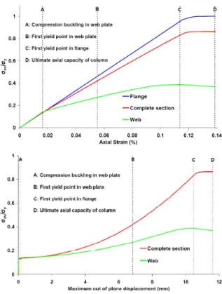
The curves corresponding to the normalized applied axial load versus a) web plate maximum out-of-plane deflection, and b) axial strains, for the two abovementioned girders are given in Figures 5(a) and 5(b), respectively. In addition, the variation in the axial stiffness of girders during the loading history is illustrated in Figure 5(c). The differential behavior of columns under compressive loading may thus be outlined as follows:
4 m column 1 m column
Figure 4. Axial buckling mode shapes.
(OA)- The behavior is linearly elastic; the distribution of axial stresses across sections is uniform until web plate buckles at A.
(AB)- After buckling, web plate behaves geometrically nonlinear and column experiences a sudden loss of axial stiffness. Web plate can carry additional loads due to the development of transverse tensile membrane stresses. With the increase of loading, the axial stiffness remains almost constant until the first yield points occur at B. Thereafter, web behaves elastic-plastic whilst flanges remain elastic. After the occurrence of buckling at A, the axial stress distribution in web is no longer uniform, (see Figure 6).
(BC) - Web behavior is both geometric and material nonlinear. With the increase of loading, yield points spread throughout the outer fibers of web plate. The first yield points in flanges occur at C.
(CD) - The column behavior is inelastic, yield points spread out in flange plates, and column experiences significant loss of axial stiffness.
In addition, Figure 5(b) shows that the axial behavior of girders and their ultimate capacities are independent of their length. In Table 2, the ultimate axial loads obtained from the FE analysis are compared to those calculated via the theoretical equation (2) [1].
a) Normalized applied axial load vs. out-of-plane deflection curves.
b) Normalized applied axial load vs. axial strain curves.
c) Axial stiffness-axial strain curves.
Figure 5. Postbuckling behavior of 1 m and 4 m columns under compression.
Table 2 - Comparison of ultimate axial loads (kN).
Columns Theory F.E. Error% 1 m 4764.5 4769.5 0.10 4 m 4751.5 4768.0 0.35
This formula utilizes the effective width method for the web plate and assumes full yielding of flanges. The theoretical and numerical results in both cases are almost identical.
(2)
max cr y
The distribution of axial stresses at different loading stages for the typical square web plate is plotted in Figure 6. As indicated, the distribution is uniform up to the buckling stage. With the increase of axial load, stresses in the middle segments decrease gradually while at edges increase and eventually reach the yield stress at the ultimate stage.
Figure 6. Axial stress distribution in the web of 1 m column at various stages.
The growth of average axial stress in the web plate ( av web
σ ), flange plates (σavflange) and the complete section ( av
section
σ ) against axial and out-of-plane displacements for the square column is given in Figure 7. According to these curves:
i- The average axial stress in the web and flange plates is uniform up to the web buckling stage. In other words, the applied axial load is proportionally distributed between flange and web plates.
Figure 7. Growth of average compressive stresses.
ii- The average axial stress in flanges linearly increase with the axial strain up to the stage when first yield points occur in flanges.
iii- After web buckling, there is an initial sudden reduction of stiffness. This reduction is then continued gradually up to C, when first yield points appear in flange plates. Web plates at this stage cease to carry further loads.
3.1.3. Effect of flange slenderness ratio
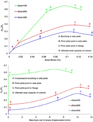
To investigate the effect of flange slenderness on the distribution of average axial stress, flange thicknesses were doubled to 60 mm and the comparative results are presented in Figure 8. It is observed that although the maximum average stress of the complete section augmented due to the increase of flange thickness, the axial capacity of web plate remained unchanged.
3.1.4. Effect of web slenderness ratio
The effect of web slenderness ratio on the behavior of girders is demonstrated in Figure 9. It is observed that by increasing the web slenderness ratio, the web buckling and ultimate capacities decrease as anticipated. However, the relative postbuckling reserves of web plates increase with their slenderness ratio.
Figure 8. Effect of flange thickness variation on the average axial stresses of the web and the complete section in the 1 m column.
Figure 9. Effect of web slenderness on the average axial stress of web plate in the 1 m column.
4 m column 1 m column
3.2. Lateral shear loading 3.2.1. Elastic buckling
Similar to the axial loading condition, the results of numerical and analytical critical shear stresses of web plates are given in Table 3. Here too, it is observed that the FE critical stresses are much closer to the theoretical clamped edge condition. The shear buckling mode shapes are also depicted in Figure 10. The numbers of local buckling half waves in the 1 m and 4 m web plates are one and five respectively, which are similar to the case of detached plates with longitudinal clamped edges.
Table 3 - Comparison of shear critical stresses (MPa).
Columns F.E.
Classic Formula (1) Simply Supported
Longitudinal Edges
Clamped Longitudinal Edges 1 m 56.25 42.21 (25% error) 56.94 (1% error) 4 m 40.85 25.26 (38% error) 42.03 (3% error)
3.2.2. Postbuckling behavior
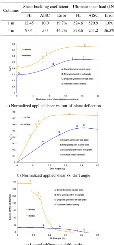
The curves corresponding to the normalized applied lateral load against maximum out-of-plane deflection and the drift angle of the two typical web plates, and their in-out-of-plane stiffness variations are presented in Figure 11. The obtained results can be discussed in three segments as follows:
(OA) - Web plate experiences elastic shear deformations. Equal principal tensile and compressive stresses develop at 45°. With the increase of lateral load, principal compressive stresses reach the critical state and web buckles at A.
(AB) - After buckling, web plate behaves geometrically nonlinear and the column experiences large loss of lateral stiffness. However, web plate can carry additional lateral loads due to the development of diagonal tension field stresses. Postbuckling deformations continue until first yield points occur within web plate at B. Up to this stage, web plate is in the elastic postbuckling state, and the stress levels in flange plates are very low.
(BCD) - Web plate behavior becomes both geometrical and material nonlinear. With the increase of lateral load, yield points spread out to form diagonal yield zones within the web plate at C. The angles at which diagonal yield zone form, with respect to the vertical axis, are 40° and 25° for the 1 m and 4 m web plates, respectively. In addition, the ratio of ultimate to buckling loads in both cases is about 1.86. It should be noted that in plated girders, flanges do not possess sufficient flexural rigidity to produce full yielding of web plate.
Table 4 compares the FE results for the shear buckling coefficients and ultimate shear strengths of the two web plates to those calculated via the AISC 360 recommendations [33]. The AISC results are considerably lower than the FE results. This is because AISC neglects the torsional rigidity of flange plates, assumes simply supported boundaries for the web plates and accounts for imperfections. On the other hand, the two results obtained for the ultimate shear strength of the square column are very close (only 1% difference); but for the longer column this difference amounts to 36%, indicating a conservative approach by the AISC.
Table 4 - Comparison of shear buckling coefficients and ultimate lateral loads.
Columns
Shear buckling coefficient Ultimate shear load (kN)
FE AISC Error FE AISC Error
1 m 12.45 10.0 19.7% 524.6 529.9 1.0% 4 m 9.04 5.0 44.7% 378.6 241.2 36.3%
a) Normalized applied shear vs. out-of-plane deflection
b) Normalized applied shear vs. drift angle
c) Lateral stiffness vs. drift angle
3.2.3. Effect of flange slenderness ratio
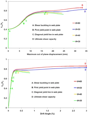
The effect of flange slenderness ratio on the behavior of slender web plates under lateral loading is demonstrated by the curves of load versus drift angle and out-of-plane deflection in Figure 12. Results show that the increase of flange thickness in the ranges considered herein does not affect the buckling capacity of web plates. However, due to the contribution of flanges, the ultimate capacity of the complete section does increase to a small extent and failure occurs at a much larger in-plane and out-of-plane displacements.
Figure 12. Effect of flange thickness on postbuckling behavior of 1 m column.
3.2.4. Effect of web slenderness ratio
The effect of web slenderness ratio on the behavior of web plates under lateral loading is presented via the out-of-plane deflection curves in Figure 13. It is observed that with the increase of web slenderness, the buckling and ultimate shear stresses decrease considerably as anticipated. However, the relative postbuckling reserves of shear increases with the increase of slenderness. In addition, the web with the slenderness ratio of 100 behaves similar to stocky plates and yield before buckle.
Figure 13. Effect of web slenderness ratio on postbuckling behavior of 1 m column.
3.3. Combined axial and lateral loading
To produce interaction curves for the critical and ultimate capacities of girders under the action of combined compression and lateral loads, three different loading procedures were considered:
A- Fixed amounts of compressive load were exerted to the columns and then incremental lateral load was applied.
B- Fixed amounts of lateral load were exerted to the columns and then incremental compressive load was applied.
C- Simultaneous incremental lateral and compressive loads were applied.
3.3.1. Axial-then-lateral loading
Various constant preset magnitudes of axial load, ranging from 0.0 to 0.8 of their respective critical loads were applied to the column. Then in each case, lateral load was applied gradually from zero to its maximum amount. The obtained results for the typical square column are given in Figure 14 in the form of lateral load versus lateral displacement and out-of-plane deflection curves. It is observed that the application of large initial axial load decreases the shear buckling load; but the ultimate capacity and in-plane stiffness of column remain unchanged. The application of initial axial load does not change the failure mechanism of column, but the predefined stages A, B and C occur at earlier displacements. The results obtained for the long column were almost similar to the above and are not repeated for brevity.
3.3.2. Lateral-then-axial loading
Figure 15 represents the effect of various initial lateral loads (up to 0.8 times critical shear) on the axial load versus axial displacement and out-of-plane deflection curves of the square column. The results show that the axial stiffness of column is not affected by the existence of preset lateral loads. However, in the cases which the preset shear loads were V Vcr =0.2 and 0.4, the failure mechanisms and mode shapes were similar to the case of pure compression. On the other hand, when V Vcr was 0.6 or 0.8, the modes were in accordance with the case of pure shear. In addition, with the increase of initial lateral load, points A to D occur at smaller axial loads and displacements.
The respective results for the 4 m column are depicted in Figure 16. Here the application of initial lateral load significantly decreases the ultimate axial load.
Figure 14. Effect of initial axial load on the shear capacity of 1 m column.
3.3.3. Simultaneous incremental axial and lateral loading
The results obtained via the application of simultaneous compressive and lateral loadings were very similar to those obtained above and thus will not be repeated here. However, these results are included in the following interaction curves.
Figure 16. Effect of initial shear load on the axial capacity of 4 m column.
3.3.4. Interaction curves
The compression-shear elastic buckling interaction curves for both web plates of the 1 m and 4 m columns are drawn in Figure 17 and are compared to the classic equation (3). This equation was intended for isolated slender rectangular plates with elastically restrained longitudinal edges [30]. In Figure 17, Pcr and Vcr denote compression and shear critical stresses, respectively. The three curves in this figure are very close and thus it can be concluded that the classic equation (3) can be safely applied to the web plates regardless of their length. It is also noted that the effect of axial load on the decrease of shear buckling load is more than the effect of shear on the axial buckling load.
(3) 1 2 = ⎟⎟ ⎠ ⎞ ⎜⎜ ⎝ ⎛ + ⎟⎟ ⎠ ⎞ ⎜⎜ ⎝ ⎛ cr cr V V P P
The lateral-axial interaction curves for the web plates and the column sections (including web and flange plates) at the ultimate stage are plotted in Figure 18. The normal and shear applied stresses
(
σ τav, av)
are normalized to their corresponding critical stresses. It is noted that the curves “ultimate-total” are obtained via the application of simultaneous loadingcondition (Section 3.3.3) and they agree well with the cases of either initial preset loading conditions (Sections 3.3.1 and 3.3.2).
Figure 17. Shear-compression buckling interaction curves.
a) 1 m column
b) 4 m column
Figure 18. Shear-compression interaction curves for the webs and the complete sections at the ultimate stage, normalized with critical stresses.
According to the results, where axial load is dominant, the average axial stress in the column at the ultimate stage linearly decreases with the increase of lateral loading. Nevertheless, the average axial stress in the web plate of square column remains constant at the ultimate stage; whereas those of the long column appears to remain constant at first, but it nonlinearly decreases during further stages of loading. Further, when lateral loading is
dominant, both buckling and ultimate shear stresses linearly decrease with the increase of axial loading.
On the other hand, if the average stresses were to be normalized with respect to their corresponding ultimate stresses
(
σu,τu)
, the interaction curves given in Figure 19 would be obtained. The dotted curves in this figure represent a circular path. According to these figures, the effect of axial load on decreasing ultimate shear capacity is more than the effect of shear on the axial capacity of web plates. In addition, where shear is dominant, with the increase of axial load, the decrease in the shear capacity of the 4 m column is more than the 1 m one. This is due to the P-delta effects in the 4 m column. Likewise, when compression is dominant, with the increase of lateral load, the decrease in the axial capacity of the 4 m column is significantly more than the 1 m column. This is due to the presence of flexural moment at the base of the 4 m column that leads to an earlier formation of plastic hinge in the compressive flange.a) web plates
b) complete sections
Figure 19. Shear-compression interaction curves at the ultimate state, normalized with ultimate stresses.
4. Conclusions
Based on the analyses carried out on the column girder models having slender webs and stocky flanges subjected to simultaneous compression and shear loads, the following conclusions are drawn:
- The buckling and ultimate lateral-axial load interaction curves for web plates and complete sections of column girders indicate that the effect of compressive load on the decrease of shear capacities is more considerable than vice versa. However, the reduction in the shear ultimate capacity is greatly influenced in longer columns due to the presence of flexural moment at the column base.
- Where lateral load is dominant, the increase of axial load is more effective in decreasing the shear buckling load than in the ultimate capacity. This decrease is more evident in longer columns due to the P-delta effects.
- Where axial loading is dominant, the increase of shear does not affect the ultimate axial capacity of square web plates. In longer columns, the ultimate axial load of web plate remains constant at first but begins to decrease by the further increase of shear. Furthermore, the decrease in the ultimate axial capacity of column sections due to the increase of shear is more significant in longer columns.
References
[1] H.G. Allen, P.S. Bulson, Background to buckling, McGraw Hill, London, 1980.
[2] R.D. Ziemian, Guide to stability design criteria for metal structures, SSRC, 6th ed. New Jersey, Wiley, 2010.
[3] J.M.Wilson, On specifications for strength of iron bridges, Trans Am Soc Civ Eng, Vol. 15, (1886) 401-403 and 489-490.
[4] H. Wagner, Flat sheet metal girder with very thin metal web, Tech Memo, National Advisory Committee for Aeronautics(NACA), (1931) 604-606.
[5] M. Stein, J. Neff, Buckling stresses of simply supported rectangular flat plates in shear, NACA: Technical note no. 1222, 1947.
[6] K. Basler, Strength of plate girders in shear, Trans. ASCE, Vol. 128, 2 (1963) 683-719.
[7] D.M. Porter, K.C. Rockey, H.R. Evans, The collapse behavior of plate girders loaded in shear, Struct Eng, Vol. 53, 8 (1975), 313-325.
[8] M.M. Alinia, M. Shakiba, H.R. Habashi, Shear failure characteristics of steel plate girders, Thin-Walled Struct, Vol. 47, 12 (2009) 1498-1506.
[9] T. Hoglund, Simply supported thin plate I girders without web stiffeners subjected to distributed transverse load, IABSE, Colloquium, Design of Plate and Box Girders for Ultimate Strength, London, (1971).
[10]Eurocode 3: Design of steel structures, European Committee for Standardization, UK (2003).
[11]M.M. Alinia, A study into optimization of stiffeners in plates subjected to shear loading, Thin Walled Struct, Vol. 43, 5 (2005), 845-860.
[12]M.M. Alinia, M. Dastfan, Behaviour of thin steel plate shear walls regarding frame members, J Construct Steel Res, Vol. 62, 7 (2006), 730-738.
[13]M.M. Alinia, M. Dastfan, The effect of surrounding members on the buckling of shear panels, In: Steel and Aluminium Structures, Oxford: RG Beale, (2007) ICSAS07.
[14]M.M. Alinia, H.R. Habashi, A. Khorram, Nonlinearity in the postbuckling behavior of thin steel shear panels, Thin-Walled Struct, Vol. 47, 4 (2009), 412–420.
[15]M.M. Alinia, A. Gheitasi, S. Erfani, Plastic shear buckling of unstiffened stocky plates, Construc Steel Res, Vol. 65, 8 (2009), 1631-1643.
[16]M.M. Alinia, S.H. Moosavi, A parametric study on the longitudinal stiffeners of web panels, Thin Walled Struc, Vol. 46, 11 (2008), 1213-1223.
[17]M.M. Alinia, S.H. Moosavi, Stability of longitudinally stiffened web plates under interactive shear and bending forces, Thin Walled Struct, Vol. 47, 1 (2009), 53-60.
[18]H.R. Habashi, M.M. Alinia, Characteristics of wall-frame interaction in steel plate shear walls, J Construct Steel Res, Vol. 66, 2 (2010), 150-158.
[19]A. Gheitasi, M.M. Alinia, Slenderness classification of unstiffened metal plates under shear loading, Thin Walled Struct., Vol. 48, 7 (2010), 508-518.
[20]H.L. Cox, Buckling of thin plates in compression, R. & M. no. 1554, British A.R.C., 1933.
[21]S. Levy, P. Krupen, Large deflection theory for end compression of long rectangular plates rigidly clamped along two edges, NACA TN 884, 1943.
[22]N. Yamaki, Post-buckling behaviour of rectangular plates with small initial curvatures loaded in edge compression, Journal of Applied Mechanics, Vol. 27, (1959) 407-414.
[23]R.M. Korol, A.N. Sherbourne, Strength predictions of plates in uniaxial compression, ASCE, Vol. 98, 9 (1972) 1965-1986.
[24]W.J. Supple, A.H. Chilver, Elastic post-buckling of compressed rectangular plates, In: Chilver AH. editor, Thin Walled Structures, (1967) 136-152.
[25]M. Bakker, Elastic post-buckling analysis of compressed plates using a two-strip model, Thin-Walled Structures, Vol. 45, 5 (2007), 502-516.
[26]G. Lindstrom, Column strength of welded I-sections in postbuckling range of component plates, Bulletin number 138, The Dept. of Structural Mechanics & Engineering, Royal Institute of Technology, Stockholm, 1982.
[27]A.J. Davids, G.J. Hancock, Compression tests of short welded I-sections, J Struct Engng, ASCE, Vol. 112, 5 (1986), 960-976.
[28]A.J. Davids, G.J. Hancock, Compression tests of long welded I-sections columns, J Struct Engng, ASCE, Vol. 112, 10 (1986), 2281-2297.
[29]A.H. Salem, M. El Aghoury, F.F. El Dib, M.T. Hanna, Ultimate capacity of I-section slender columns, J Constr Steel Res, Vol. 60, (2004) 1193-1211.
[30]E.Z. Stowell, E.B. Schwartz, Shear and uniform longitudinal compression, NACA, ARR, No. 3K13, (1943).
[31]J.E. Harding, R.E. Hobbs, B.G. Neal, J. Slatford, Parametric Study on Plates under Combined direct and Shear In-Plane Loading, CESLIC Report BG 44, Eng. Struc. Laboratories, Civil Eng. Dept., Imperial College, 1976.
[32]J. Zaras, J. Rhodes, M. Krolak, Buckling and Post-buckling Behaviour of Rectangular Plates under Linearly Varying Compression and Shear: Part 1- Theoretical Analysis, Thin-Walled Struct, Vol. 14, 1 (1992), 59-87.
[33]AISC, ANSI/AISC 360-05: Specification for structural steel buildings, American Institute of Steel Construction Inc, Chicago, Illinois, USA (2007).