Heat Transfer Augmentation through Electric Fan Heater Using
Computational Fluid Dynamics
M Ahmad1, M Shafiq2 and I. A. Chaudhry3
1. Research Scholar Mathematics Department University of Engineering and Technology, Lahore, Pakistan 2. Assistant Professor Mathematic Department University of Engineering and Technology, Lahore, Pakistan
3. Professor, Mechanical Engineering Department Faculty of Mechanical Engineering University of Engineering and Technology, Lahore, [email protected]
Abstract
Air flow through electric fan heater channel is governed by coupled, non-linear partial differential equations; these equations have to be solved within on irregular domain subject to various initial and boundary conditions. Computational Fluid Dynamics (CFD) replaces fluid flow equations by a set of algebraic equations, these algebraic equations can be solved using digital computers. Wall to air heat transfer augmentation is the most critical part of the electric fan heater design process. The objective of this study is to design an electric fan heater with heating channel 70cm long by 70cm wide by 5cm high. Wall to air heat transfer augmentation will be accomplished by placing turbulence promoters inside the heating channel. The effects of turbulence promoters on heat transfer augmentation will be studied using Computational Fluid Dynamics (CFD), Fluent.
Key Words
: CFD, Heat Augmentation, Fluent1. Introduction
For the last 20 years, electronics has developed and become a part of our lives. As the number of applications that involved electronics increases, the successful operation of electronic systems becomes a major consideration. Electric fan heaters are among the electronic devices which are being used intensively these days. In winter, the use of electric fan heaters is un-avoidable, they are used in houses, offices, class-rooms, vehicles and even in industries. Electric fan heaters provide us warm air; this is accomplished by blowing air through heating channel. That is why, wall to air heat transfer enhancement is the most critical part of electric fan heater design. We will use Fluent to examine the wall to air heat transfer augmentation. Wall to air heat transfer will be accomplished by placing turbulence promoters in the heating channel. We would look at the effects of protrusions height; we will model the heating channel for the range of Reynolds’s numbers.
Fluent solves Fluid Dynamics equations by discretizing a continuous domain into a finite number of control volumes. The solution that any such numerical program generates should be validated by comparing it to a set of experimental data; but once
its validity has been established, the program can be used for various design purposes, within the limits imposed by assumptions on which it was based.
2. Literature Review
P. Sivashanmugam, S. Suresh and P.K. Nagarajan [1] studied the heat transfer augmentation in a circular tube fitted with regularly spaced helical inserts using Fluent and compared the simulation data with literature values.
Demirel and HH, Al-Ali and BA, Abu-Al-Saud [2] (1999) studied the characteristics of wall to air heat transfer in a large rectangular packed duct and found that introduction of spherical packing into the air flow passage increases the wall to air heat transfer approximately three times compared with that of empty duct.
Greiner, Chen and Wirtz [3] studied the heat transfer augmentation in grooved channels and found 350% heat transfer enhancement over the smooth channel.
Han, Zhang and Lee [4] studied the effects of rib orientations and angles to enhance heat transfer. They found that V-shaped ribs with 45 and 60-degree angles gave the highest heat transfer enhancement.
3.
Geometry and Grid Arrangement
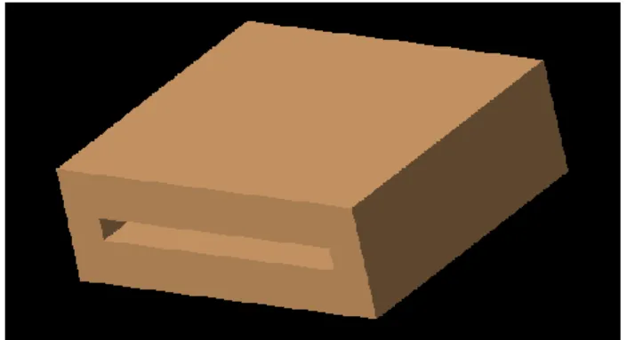
The geometry of heating channel under consideration is illustrated in figure 1. The heating channel passing through the body of electric fan heater is 70cm long by 70cm wide by 5cm high. There are nine rib-like copper protrusions inside the channel; four protrusions are on the upper side and five are on the bottom of the channel. Each protrusion is 70cm long by 1cm wide by 1cm high.
Fig.1 Heating channel
As the results are invariant with respect to z-direction due to insulated side walls, so we take 2-D Fluent model for the analysis of results.
Fig. 3 Grid for heating channel
The geometry and the grid were generated using Gambit the preprocessing module of the Fluent code. The geometry and grid for both, the smooth channel and the channel with protruding ribs were created in Gambit and imported into Fluent.
4. Results from Literature
The hydraulic diameter,
D
H, for parallel plates is twice the channel height, H:H
D
H2
(1)The Reynolds number is:
H D
VD
R
H (2)
The Nusset number for fully developed turbulent flow (
2000
H
D
R
) in a rectangular channel [5] is:4 . 0 8 . 0
Pr
Re
023
.
0
H
D H
k
hD
Nu
(3)Where h is the coefficient of heat transfer, and
k
stands for the thermal conductivity.The friction factor for fully developed turbulent flow (
2000
H
D
R
) in a rectangular channel [6] is:25 . 0
312
.
0
H
D
R
f
(4)5. Numerical Solution
Using Fluent post processing module, we can have velocity, temperature, total heat flux etc at every point in the flow field. The Nusselt number is calculated as
)
)(
(
''
k
D
T
T
q
k
D
h
Nu
Hw H flu
(5)
Where
q
'' is the total surface heat flux,T
w is the temperature of the wall, andT
represents the temperature of the air at the inlet.The friction factor is calculated as
L
V
PD
f
Hflu
2
2
1
(6)In this equation,
P
is the pressure drop near the end of plate, L is the length corresponding toP
, V is the mean velocity, and is the fluid density.6. Results And Discussion
6.1 Smooth ChannelHere we consider the smooth channel to verify the validity of fluent results. We consider three different cases with following properties of air at 300k temperature [5].
Table 1 Properties of air at 300k
Property Symbol Value
Density 3
/
1774
.
1
kg
m
Kinematic
viscosity
1
.
569
10
m
/
s
2 5
Dynamic
viscosity
1
.
8462
10
kg
/
ms
5
Conductivity
k
0
.
02624
W
/
mk
Specific heat p
C
1005
.
7
J
/
Kgk
Prandle number
Pr
0
.
708
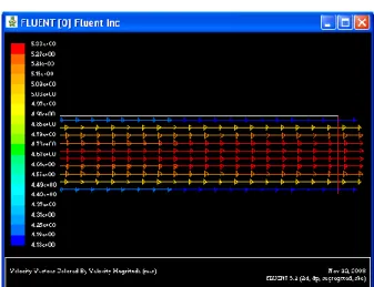
In this case the inlet velocity of the channel was taken as 5m/s and 12m/s. The upper and bottom walls of the channel were kept at temperature 380k. Fluent was run for different grid cells in the y-direction, and we observed that satisfactory results are obtained for 10 cells in the vertical direction. The following data was obtained from Fluent.
Fig. 4 Velocity magnitudes at different positions at bottom plate (5m/s)
Fig.5 Total heat flux at different positions at bottom plate (5m/s)
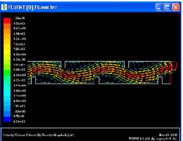
Fig.6 Velocity vectors at different positions
Having data from Fluent and using excel sheet, we have the following graphs.
Fig. 7 Comparison of Fluent and Baseline results (5m/s)
Baseline Vs Fluent
1 10 100 1000
26000 27000 28000 29000 30000 31000 32000
Re
Nu
Baseline Fluent
V=5m/s, 10 cells in y direction
Fig. 8 Comparison of Fluent and Baseline results (12m/s)
Figure 7, 8 and 9 show that the Fluent results are very close to the baseline results.
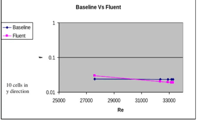
Fig. 9 Comparison of Fluent and Baseline results for friction factor
6.2 Effect of Protruding Ribs
There are nine thin rib-like copper protrusions inside the channel; four protrusions are on the upper side and five are on the bottom of the channel. Each protrusion is 1cm high by 1cm wide by 70cm long.
Fig.10 Velocity vectors at different positions (1cm Rib)
Figure 7 shows plots of velocity vectors for channel with protruding ribs 1 cm. From the figure, we can observe that the mixing of air has increased and therefore causes wall to air heat transfer enhancement.
Fig.11 Baseline Vs Enhanced (1cm Rib)
Fig.12 Comparison of Fluent (1.0cm) and Baseline results for friction factor
Figure 11 plots Nu versus Re results for protrusions height of 1 cm as well as the baseline smooth channel results. Figure 12 plots f versus Re results for protrusions height of 1 cm as well as the baseline smooth channel results. The results show larger increases in the Nusselt number over the entire Reynolds number range. It has been found that the introduction of the protruding ribs (1cm) into the air passage increases the wall-to-air heat transfer approximately 1.3-3.5 times compared with that of smooth channel, correspondingly, the friction factor increases approximately 6-30 times.
It has been found that the introduction of the protruding ribs (1.5cm) into the air passage increases wall-to-air heat transfer approximately 1.5 – 4.5 times compared with that of smooth channel, correspondingly, the friction factor increases approximately 10-50 times.
V=5m/s Rib Height 1cm
Baseline Vs Enhanced
1 10 100 1000
1000 10000 100000
Re
Nu
Baseline Enhanced
Baseline Vs Fluent (1.0 cm)
0.01 0.1 1 10
0 10000 20000 30000 40000 50000
Re
f
Baseline Fluent (1.0cm)
10 cells in y direction Baseline Vs Fluent
0.01 0.1 1
25000 27000 29000 31000 33000
Re
f
Baseline Fluent
10 cells in y direction
Fluent Vs Baseline
1 10 100 1000
62000 64000 66000 68000 70000 72000 74000 76000 78000
Re
Nu
Fluent Baseline
V=12m/s, 10 cells in y direction
Fig. 13 Velocity vectors at different positions (1.5cm Rib)
Fig.14 Baseline Vs Enhanced (1.5cm Rib)
Fig.15 Comparison of Fluent (1.5cm) and Baseline results for friction factor
7. Conclusions
CFD simulation for the heat transfer augmentation in a rectangular heating channel with ribbed walls has been explained in this research paper using Fluent version 6.2, the data obtained by simulation show that protruding ribs increase the wall to air heat transfer as well as the friction factor.
8
References
[1] P. Sivashanmugam, S. Suresh and P.K. Nagarajan, “CFD Simulation of Heat Transfer Augmentation in a Circular Tube Fitted with Regularly Spaced Helical Twist Inserts in Laminar Flow under Constant Heat Flux”
www.ese.iitb.ac.in/~aer2006/papers/PS_094.doc
[2] Demirel, Y; Al-Ali, HH; Abu-Al-Saud, BA. “Enhancement Of Convection Heat-Transfer In A Rectangular Duct,” ELSEVIER SCI LTD, APPLIED ENERGY; pp: 441-451; Vol: 64
[3] Greiner, M., Chen, R.F. and Wirtz, R.A., 1991. “Passive Heat Transfer Enhancement on a Flat Surface in a Grooved Channel,” ASME/JSME Thermal Engineering Proceedings Vol.3, p.97-101.
[4] Han, J.C., Zhang, Y.M. and Lee, C.P., 1991. “Augmented Heat Transfer in Square Channels with Parallel, Crossed, and V-Shaped Angled Ribs,” ASME-HTD, Vol. 113, p. 590-596.
[5] J.P. Holman, “Heat Transfer Ninth Edition”,
McGraw-Hill, Inc.
[6] Victor L. Streeter, E. Benjamin Wylie, “Fluid Mechanics”, McGraw-Hill, Inc
Baseline Vs Enhanced
1 10 100 1000
1000 10000 100000
Re
Nu
Baseline Enhanced
V=5m/s Rib Height 1.5cm
Baseline Vs Fluent(1.5cm)
0.01 0.1 1 10
0 10000 20000 30000 40000 50000 60000
Re
f
Baseline Fluent(1.5cm)
10 cells in y direction