Unstiened Extended End Plate Connection
M.R. Mohammadi-Shoreh
1and M. Mod
In this paper, a new analytical method is presented that can be used to determine the behavior of a particular steel beam-to-column extended end plate connection in linear and nonlinear regions. A common means of forming a rigid joint between a universal beam and column is to weld an end plate to the beam end and then to bolt it to the column. A physically based analytical method that can predict the behavior of bolted and extended end plate eave connections, using the connection dimensions as input, is presented. This article demonstrates an analytical procedure for the establishment of elastic and plastic parts of theM curve of this form of connection. An
analytical method is proposed for the extended end plate joints having four bolts in the tension region and without any stiened plate. However, the presented technique can also properly be extended to other types of this form of connection. An extensive approach to estimate the plastic stiness of the connection has also been performed. Comparison is made on a series of test results for a range of bolted end plate moment connections and good agreement is achieved. Furthermore, the authors believe that the method presented shall eciently serve design engineers in real design conditions.
INTRODUCTION
Beam-to-column end plate connections have been the subject of increasing interest and study since 1960 [1,2]. Several researchers have been working to understand connection structural behavior, focusing, at rst, on the hypothesis of similarity between the behavior of end plate and T-stub connections. According to this view, other works can be pointed out, such as those developed by Kato and McGuire [3] and Packer and Morris [4]. Krishnamurthy [5] conducted a nite element analysis of moment end plate connections and developed a practical design method for the beam-to-column end plate connections. Based on his analytical study of the end plates, as well as a series of experimental tests, Krishnamurthy developed a design procedure, which was eventually presented in the AISC Manual of Steel Construction (1980). Other recent studies have used the nite element method and multi-variable regression analysis developed by Gebboken et al. [6], Sherbourne and Bahaari [7-9], Bursi and Jaspart [10-12] and Nemati et al. [13].
1. Department of Civil Engineering, Sharif University of Technology, Tehran, I.R. Iran.
*. Corresponding Author, Department of Civil Engineering, Sharif University of Technology, Tehran, I.R. Iran.
Experimental investigations on the static and cyclic performance of end plate moment connections have also been conducted by Jenkins et al. [14], Cruz et al. [15], Riberio et al. [16], Adey et al. [17] and Yorgun et al. [18].
In addition, some other studies have introduced the standardized moment-rotation function or ana-lytical approach for predicting the moment rotation behavior of extended end plate connections [9-26].
Experimental study of the connections is very expensive and it is impractical to experiment with all the dierent types and sizes of connections. On the other hand, the 3-D nite element models are fairly complicated for simulation of the connections, as well as the whole structure.
The objectives of this investigation are:
To prepare a reliable, approximate model that can
easily be constructed and be simple enough for use as a connecting element in the nonlinear analysis of steel structures;
To study the behavior of extended end plate
connec-tions, which is widely used in high-rise buildings and industrial structures and to develop a step-by-step analytical technique to prepare the capacity for this type of connection;
apply-Figure1. Common types of end plate connections.
ing the same test problems and by comparing the results with nite element models, as well as with experimental data;
To inspect the important factors in the behavior
of this type of connection, through on-parametric study.
THEORY OF THE ANALYTICAL MODEL
The popularity of moment resisting joints with ex-tended connecting end plates can be attributed mainly to the simplicity and economy associated with their design, fabrication and erection. Four common types of tension bolted, extended, end plate connections are shown in Figure 1. These connections are used frequently to achieve a relatively rigid connection behavior. In this paper, the behavior of an extended end plate connection without column stieners and end plate, type I, has been studied.
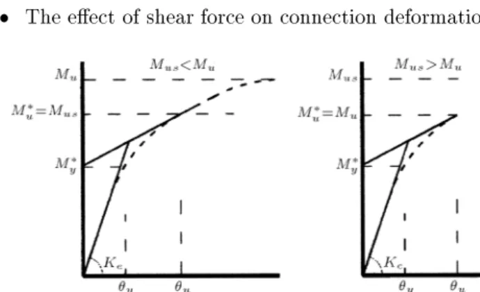
Figure 2 schematically shows the moment rotation behavior of a variety of commonly used end plate connections. The initial slope of an M curve is
dened as initial stiness,K
e. The ultimate moment, M
u, is dened as the maximum moment that can be
transmitted by the connection. If connection capacity is greater than the beam or column ultimate moment, then M
u is dened as the lowest ultimate moment
capacity of the beam and column. However, if the connection capacity is smaller than the beam and column ultimate moment, then M
u shall be dened
as M
u. Consequently, the slope of an
M curve
at ultimate momentM
u, is dened as plastic stiness, K
p.
EVALUATION OF MODEL PARAMETERS
To study the behavior of the connection, the following assumptions are made.
The end plate should be exactly attached to the
beam;
The eect of shear force on connection deformation
Figure 2. Schematically connection moment rotation
behavior, which is shown in Figure 3;
All the bolts are preloaded and a pretension load,
limited to 40 percent of the actual yield stress, was applied;
In-plane deformations are negligible.
To overcome the implementation of a complex, nonlinear, nite element analysis in the prediction of the connection behavior, a simpler approach was developed in the form of a so called \Component Method" [25]. Briey described, the method consists of modeling a joint as an assembly of extensional spring and rigid links, whereby the springs represent a specic part of a joint that, depending on the type of loading, makes an identied contribution to one or more of its structural properties. Considering the properties of a moment rotation curve, it is evident that in order to present a bilinear curve, the following requirements are needed:
M= 0 at = 0; (1)
dM d
=K e at
= 0; (2)
M y=
K e
y
; (3)
dM d
=K p at
M!M u
; !
u
: (4)
In order to obtain a bilinear curve, the parameters
K e
;M y
;M u and
K
p must be predicted. This can be
done analytically, as described in the following sections. Figure 4 identies the various geometric parameters, which have been used in the present study.
Figure3. Connection material stress-strain curve.
Figure4. Unstiened extended end plate connection
geometry.
Evaluation of Initial Stiness
To evaluate the initial stiness of the connections, the following assumptions are made:
The center of rotation of the connection should
coincide with the middle of the beam lower ange;
Applied force from the beam upper ange is
consid-ered for total plate width;
Centerlines of bolts are assumed as a clamped edge
for plate;
The beams act as rigid members.
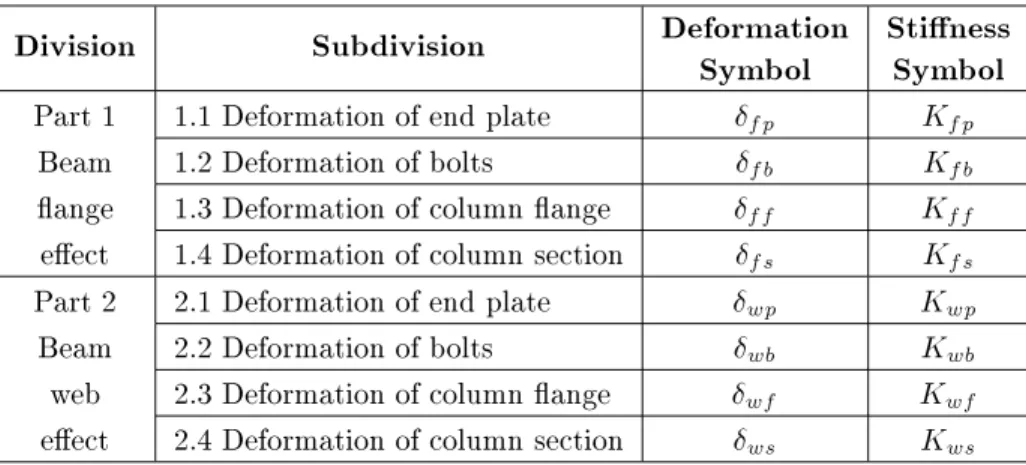
The rotational stiness of a connection is directly related to the deformation of individual connection elements. The components, which contribute to the deformation of the connection, are: (1) End plate, (2) Tension bolts, (3) Column ange and (4) Column section. However, because of the complexity of these deformations, they have been separated into two parts. These parts contain deformation caused by beam ange and beam web and each of these deformations are made up of four parts. These divisions shall be considered as presented in Table 1.
The application of the method to a typical, bolted, end plate, beam-to-column joint is illustrated in Figure 5. A general expression for initial stiness,K
e,
Table 1. Considered deformations to calculate the initial stiness.
Division
Subdivision
Deformation
Symbol
Stiness
Symbol
Part 1 1.1 Deformation of end plate fp
K fp
Beam 1.2 Deformation of bolts fb
K fb
ange 1.3 Deformation of column ange ff
K ff
eect 1.4 Deformation of column section fs
K fs
Part 2 2.1 Deformation of end plate wp
K wp
Beam 2.2 Deformation of bolts wb
K wb
web 2.3 Deformation of column ange wf
K wf
eect 2.4 Deformation of column section ws
K ws Table 2. Expressions for initial stiness,K
e. K e= 1 1 K fp + 1 K fb + 1 K ff + 1 K fs + 1 K w p + 1 K w b + 1 K w f + 1 K w s = E:b:h 2 b (1 e ) 1 Ro + 1 2nR 3 + 1 R 4 + 1 R 5 + 6e R 2 R 2 R 1 + 1 R 3 + 1 R 4 + 2 R 5 a = 2
b+g; e= t w b b fb t w b b fb +6 t fb d w b + t fb d w b 3 = 1 1+6 A fb A w b Q= 208(1 +
d b b) + 33
:6 g
2 b
2(1 + b d
b) + 13
g 4 b
4(1 + b 3 d 3 b ) R 0= t 3 p b fc =b 2 0:455b 2 +1:56t 2 p ; R 1= 8 21(1 v 2 ) Q:t 3 p =g 7g 2 +6t 2 p 8+ g 2 b 2 + g 2 d 2 b R 2= 64 147 Q:b 2 =d b 13d b +16b g 4 b 3 ; R 3= 4b:(t p +t fc )
1:33d bo+ 1 2 tp:tfc t p +t fc 2 R 4= 4a :t 3 fc =(g t w c d bo t p ) 3 b: 1+3:12 t 2 fc (g tw c d bo tp) 2 ; R 5= 24I c =b a 3 +16d 3 b + 24 7 d 2 c a
is formulated in Table 2, which shows, in detail, the ex-pressions for the initial stiness of various components of unstiened, extended, end plate eave connections.
Evaluation of Ultimate Moment
The various components contributing to the overall response of a generic, end plate, beam-to-column, steel joint include the following:
1. Column web in shear, compression and tension, 2. Column ange in bending,
3. End plate in bending, 4. Bolts in tension and shear,
5. Beam ange and beam web in tension and compres-sion.
On the basis of these assumptions, the moment capacity of an unstiened connection depends on the strength of the individual connection elements. Various investigations [4,27] have shown that an unstiened connection will begin to lose its ability to sustain further loading when one or more of the following failure modes occurs:
1. Bolt failure (in tension),
2. Formation of the end plate plastic mechanism, 3. Formation of the column ange plastic mechanism, 4. Shear yielding, buckling or crippling of the column
behavior, using the bending theory, the simplied rela-tionship between the moment acting on the connection,
M, and beam ange force,F, can be given as follows: F= M d b 1 1 + A
f 6Aw = M e d b : (5)
If the moment of the connection increases until the plastic hinges occur at the beam, using the plastic theory, the beam ange force can be obtained as:
F= M d b 1 1 + A
f 4Aw = M p d b : (6)
In seismic design, connections should bear beam mo-ment capacity. Thus, the value of
p is considered
as . Then, each of the possible failure modes shall
be considered in terms of F and, consequently, the
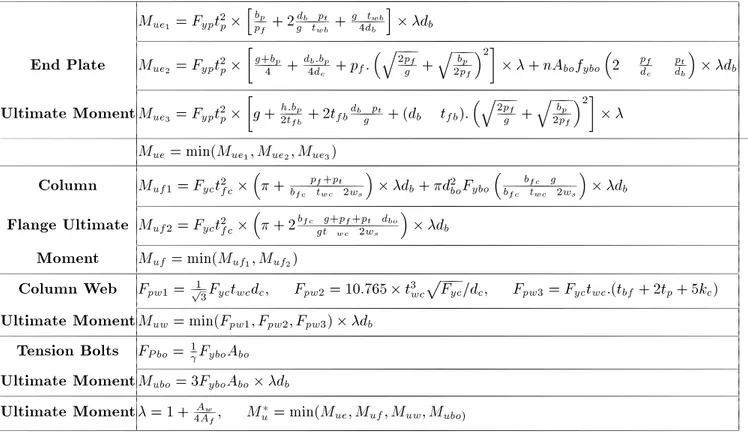
ultimate force for each mentioned component (end plate, tension bolt, column ange and column section) can be evaluated. Thus the lowest value corresponding to the following failure modes will present the amount ofM
u. Besides, Table 3 summarizes the equations used
to evaluate M
u for this type of extended end plate
connection.
Then, using the plastic theory, the corresponding load-deformation curve will be calculated. According to extensive study in this area [28], the yielding moment of the end plate connection, M
y, can be evaluated as
the following:
M y =
:7min(M ue ;M uf ;M us) ; (7) M y= 1 1 K p =K e M y : (8)
Evaluation of Plastic Stiness
There is no exact applicable analytical method for calculation of the plastic stiness of connections and, therefore, usually, test results are used to estimate the value of plastic stiness. For example, the ratio of
K p
=K e
:05 for unstiened end plate connections
is suggested by Sherbourne et al. [23]. This ratio is resulted by testing and includes the eects of strain hardening and changes in geometry of the connection. Therefore, in this article, the equations used to evaluate
K
p are formulated in Table 4. Table3. Considered mechanisms to calculate the ultimate moment. M ue1 = F yp t 2 p h bp pf + 2
db pt g tw b +
g tw b 4db
i
d
b
End Plate
M ue2 = F yp t 2 p g+bp 4 + db:bp 4d e + p f : q 2pf g + q bp 2p f 2 +nA bo f ybo 2 pf d e pt d b d bUltimate Moment
M ue3 = F yp t 2 p g+ h:b p 2tfb + 2 t
fb d
b pt g + (
d b t fb) : q 2p f g + q b p 2p f 2 M
ue= min( M ue1 ;M ue2 ;M ue3)
Column
M uf1= F yc t 2 fc + p f +p t b fctw c 2ws d b+ d 2 bo F ybo b fc g b fc
tw c 2ws
d
b
Flange Ultimate
M uf2= F yc t 2 fc + 2bfc g+pf+pt dbo g t w c 2w s d b
Moment
Muf = min( M
uf1 ;M
uf2)
Column Web
F pw1= 1 p 3 F yc t wc d c ; Fpw2= 10 :765t
3 wc p F yc =d c ; F pw3= F yc t wc :(t
bf+ 2 t
p+ 5 k
c)
Ultimate Moment
Muw= min( F pw1 ;F pw2 ;F pw3) d b
Tension Bolts
F Pbo=1 F ybo A bo
Ultimate Moment
M ubo= 3F ybo A bo d b
Ultimate Moment
= 1 + Aw 4Af
; M
u = min( M ue ;M uf ;M uw ;M ubo)
Table4. Expressions for plastic stiness,K p.
Failure
Mode
End Plate or Column Flange
or Bolt Failure
Column Web
Failure
Beam or Column
Plastic Hinge in
Plastic
Stiness
K p = 1 1 K p pfb + 1 Ke w eb + 1 Ke K p= 1 1 K e pfb + 15:3 Ke K p = Ke 11 K
p pfb=
40Ed 2 b 16 d 3 e +6dep 2 t 2p 3 t bp:t 3 p + b 3 fc +6b fc g 2 2g 3 de:t 3 w c ; K e= 1 1 K e pfb + 1 K
e w eb K
e web= 1 1 K fs + 1 Kw s ; K
e pfb=
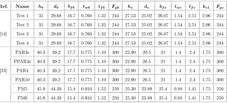
1 1 K fp + 1 K fb + 1 K ff + 1 Kw p + 1 K w b + 1 K w f Table5. Schedule of dierent test problems, beam and column properties.
Ref. Name
h b d b b fb t wb t fb F yb h c d c b fc t wc t fc k c1 F ycTest 1 31 29.68 16.7 0.760 1.32 244 27.53 25.02 26.07 1.54 2.51 2.06 244 Test 2 31 29.68 16.7 0.760 1.32 244 27.53 25.02 26.07 1.54 2.51 2.06 244 [14] Test 3 31 29.68 16.7 0.760 1.32 244 27.53 25.02 26.07 1.54 2.51 2.06 244 Test 4 31 29.68 16.7 0.760 1.32 244 27.53 25.02 26.07 1.54 2.51 2.06 244 PAR3e 40.3 39.2 17.7 0.775 1.10 300 22.90 20.5 21 1.4 2.4 1.75 300 PPAR3e 40.3 39.2 17.7 0.775 1.10 300 22.90 20.5 21 1.4 2.4 1.75 300 [23] PAR4 40.3 39.2 17.7 0.775 1.10 300 22.90 20.5 21 1.4 2.4 1.75 300 PAR10 40.3 39.2 17.7 0.775 1.10 300 22.90 20.5 21 1.4 2.4 1.75 300 PM5 45.9 44.38 15.4 0.910 1.52 250 25.30 23.89 25.4 0.88 1.41 1.75 250 PM6 45.9 44.38 15.4 0.910 1.52 250 25.30 23.89 25.4 0.88 1.41 1.75 250
* All dimensions are in cm and MPa.
EXAMPLE PROBLEMS
To test the relative accuracy of the presented analytical method and, also, in order to consider various combi-nations of beams and columns in terms of load carrying capacity, ten unstiened, extended, end plate examples from dierent studies are carefully selected. Beam and column properties are shown in Table 5 and properties of other components of the connections are shown in Table 6. The modulus of elasticity of all components is considered asE= 21010
9 N/m2.
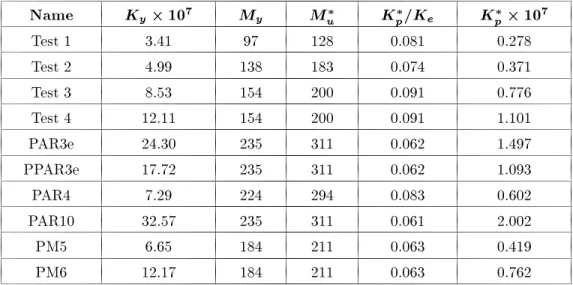
Using the presented analytical method, the initial stiness, yielding moment and ultimate moments of each connection are calculated, respectively. Also, the ratio ofK
p =K
e for every case is calculated and listed
in Table 7. In addition, to show the accuracy of the results, the bilinear curve that is obtained with the presented technique and the experimental moment rotation curve for four cases is illustrated in Figure 6. Also, the presented bilinear curve and the nite element
prediction curve for six specimens are illustrated in Figure 7. The presented bilinear curve passes through three points. The rst point is origin, the second is (
y ;M
y) and the third is (
u ;M
u).
As noted,
y is obtained by \ M
y =K
e" and
u is
equal to \ y+ (
M u M y) =K p".
CONCLUSION
In this investigation, an analytical procedure for es-timation of the behavior of unstiened extended end plate connections has been presented. The theory in this method is mainly based on the theory of a yield line mechanism. Substitution of the values of material property and the dimensions of the connection in the proposed formulas lead to calculation of the initial stiness, yielding moment and ultimate moment stiness of the connection, which demonstrates the connection behavior and which can be used by sci-entists and engineers. Comparison of the results in
Test 3 20 11.0 6.0 13 2 4.34 6.66 1 2.03 244 627 Test 4 20 11.0 6.0 13 2 4.34 6.66 1 2.54 244 627 PAR3e 21 12.6 7.15 12 2.4 5.6 7.7 1 3.0 300 627 PPAR3e 21 12.6 7.15 12 2.4 5.6 7.7 1 2.4 300 627 [23] PAR4 21 12.6 7.15 12 2.4 5.6 7.7 1 1.5 300 627 PAR10 21 12.6 7.15 12 2.4 5.6 7.7 1 4.0 300 627 PM5 25.4 12.4 6.76 12 2.4 5.0 7.52 1 2.0 250 627 PM6 25.4 12.4 6.76 12 2.4 5.0 7.52 1 3.0 250 627
* All dimensions are in cm and MPa.
Figure6. Comparison between test and prediction results.
Figure 6 shows a good agreement between experimental data and the presented technique in this investigation. Also, comparison of the results in Figure 7 shows an approximate agreement between nite element predic-tion and the presented technique in this investiga-tion.
The signicant points of this investigation can be summarized as follows:
Ratio ofK p
=K
evaries between 0.04 and 0.14 for end
plate connections.
If the connection ultimate moment, M
u, is greater
than the beam or column ultimate moment, then, the ratio ofK
p =K
evaries between 0.09 and 0.14. If the connection ultimate moment, M
Table7. Results of the presented analytical method.
Name
K y10
7M y
M u
K p
=K e
K p
10
7Test 1 3.41 97 128 0.081 0.278
Test 2 4.99 138 183 0.074 0.371
Test 3 8.53 154 200 0.091 0.776
Test 4 12.11 154 200 0.091 1.101
PAR3e 24.30 235 311 0.062 1.497
PPAR3e 17.72 235 311 0.062 1.093
PAR4 7.29 224 294 0.083 0.602
PAR10 32.57 235 311 0.061 2.002
PM5 6.65 184 211 0.063 0.419
PM6 12.17 184 211 0.063 0.762
*All dimensions are in kN.m and kN.m/rad.
A
bo area of each bolt A
fb area of beam ange A
f area of beam ange A
w area of beam web E modulus of elasticity E
bo modulus of elasticity of bolt F beam ange force
K
e initial stiness of the connection K
p plastic stiness of the connection M
y yield moment applied to connection M
u total moment applied to connection M
ue total moment applied to end plate M
uf total moment applied to column ange M
uw total moment applied to column web M
ub total moment applied to bolts ;
e ;
p coecients dened in Equations 5
and 6
displacement (general)
y total rotation in elastic zone
u total rotation
REFERENCES
1. Sherbourne, A.N. \Bolted beam-to-column connec-tions", The Structural Engineer, 39(6), pp 203-210
(1961).
2. Douty, R.T. and McGuire, W.F. \High strength bolted moment connections",Journal of Structural Division, ASCE, No ST2,91(4), pp 101-128 (1965).
3. Kato, B. and McGuire, W. \Analysis of T-stub ange to column connections", Journal of Structural Divi-sion, ASCE,99(5), pp 865-888 (1973).
4. Packer, J.A. and Morris, L.J. \A limit state design method for the tension region of the bolted beam-to-column connections",The Structural Engineer,55(10),
pp 446-458 (1977).
5. Krishnamurthy, N. \A fresh look at bolted end plate behaviour and design", Engineering Journal, AISC, 2nd Quarter,15(2), pp 39-49 (1978).
6. Gebboken, N., Rothert, H. and Binder, B. \On the numerical analysis of end plate connections",Journal of Constructional Steel Research, 30(2), pp 177-196
(1994).
7. Sherbourne, A.N. and Bahaari, M.R. \3D simulation of end-plate bolted connections",Journal of Structural Engineering, ASCE,120(11), pp 3122-3136 (1994).
of bolted connections to unstiened columns-II T-stub connections",J. Constr. Steel Res.,40(3), pp 189-223
(1996b).
10. Bursi, O.S. and Jaspart, J.P. \Benchmarks for nite element modeling of bolted steel connections", J. Constr. Steel Res.,43(1-3), pp 17-42 (1997a).
11. Bursi, O.S. and Jaspart, J.P. \Calibration of a nite element model for isolated bolted end plate steel connections",J. Constr. Steel Res.,44(3), pp 225-262
(1997b).
12. Bursi, O.S. and Jaspart, J.P. \Basic issues in the nite element simulation of extended end plate connections",
Computers and Structures,69, pp 361-382 (1998).
13. Nemati, N., Houedec, D.L. and Zandonini, R. \Nu-merical modeling of the cyclic behavior of the basic components of steel end-plate connections",Advances in Engineering Software,31, pp 837-849 (2000).
14. Jenkins, W.M., Tang, C.S. and Prescott, A.T. \Mo-ment transmitting end plate connections in steel connections, and proposed basis for ush end plate design",The Structural Engineer,64A(5), pp 121-132
(1986).
15. Cruz, P.J.S., Simoes da Silva, L., Rodrigues, D.S. and Simoes, RAD. \Data base for the semi-rigid behaviour of beam-to-column connections in seismic regions",J. Constr. Steel Res.,46(1-3), pp 233-234 (1998).
16. Riberio, L.F.L., Goncsalves, R.M. and Castiglioni, C.A. \Beam-to-column end plate connections. An ex-perimental analysis", J. Constr. Steel Res., 46(1-3),
paper No. 304, pp 264-266 (1998).
17. Adey, B.T., Grodin, G.Y. and Chenye, J.J.R. \Ex-tended end-plate moment connections under cyclic loading",J. Constr. Steel Res.,46(1-3), paper No. 133,
pp 435-436 (1998).
18. Yorgun, C. and Bayramoglu, G. \Cyclic test for welded-plate sections with end-plate connections",
Journal of Constructional Steel Research, 57(12), pp
1309-1320 (2001).
19. Frye, M.J. and Morris, G.A. \Analysis of exibility connected steel frames", Canadian Journal of Civil Engineering,2(3), pp 280-291 (1975).
20. Krishnamurthy, N., Huang, H.T., Jeery, P.K. and Arery, L.K. \Analytical M curves for end plate
connections", J. Struct. Div., ASCE,105(1), pp
133-145 (1979).
21. Yee, Y.L. and Melchers, R.E. \Moment-rotation curves for bolted connections", Journal of Structural Engi-neering, ASCE,112(3), pp 615-635 (1986).
22. Attiogbe, E. and Morris, G. \Moment-rotation func-tions for steel connecfunc-tions", Journal of Structural Engineering, ASCE,117(6), pp 1702-1718 (1991).
23. Sherbourne, A.N. and Bahaari, M.R. \Finite element prediction of end-plate bolted connection behavior. I: Parametric study", J. Struct. Engrg., ASCE,123(2),
pp 157-164 (1997a).
24. Sherbourne, A.N. and Bahaari, M.R. \Finite element prediction of end-plate bolted connection. Behavior II: Analytic formulation", J. Struct. Engrg., ASCE,
123(2), pp 165-175 (1997b).
25. Simoes da Silva, L. and Giroo Coelho, A. \A ductility model for steel connections", J. Constr. Steel Res.,
57(1), pp 45-70 (2001).
26. Mod, M., Ghorbani, M. and McCabe, S.L. \On the analytical model of beam-to-column semi-rigid
con-nections, using plate theory",Thin-walled Structures, (39), pp 307-325 (2001).
27. Witteveen, J., Stark, J.W., Bijloard, F.S. and Zoete-meijier, P. \Welded and bolted beam-to-column con-nections", Journal of Structural Engineering, ASCE,
108(2), pp 433-455 (1982).
28. Mohammadi Shoreh, M.R. \On the analytical model of beam-to-column Semi-Rigid steel connection", Thesis Presented to the Civil Department of Sharif University of Technology, Tehran, Iran, in partial fulllment of the requirements for the degree of Master of Science (2002).