A New Analytical Method on
the Field Calculation of Interior
Permanent-Magnet Synchronous Motors
A. Kiyoumarsi
, M.R. Hassanzadeh
1and M. Moallem
2Although there are analytical methods for eld calculation in surface-mounted synchronous motors, accurate analytical methods for predicting airgap ux density distribution in Interior-type Permanent-Magnet (IPM) synchronous motors are not available. In this paper, a novel method for analytical prediction of ux distribution, based on Schwarz-Christofell transformation techniques, is proposed to evaluate the airgap ux density distribution in an IPM motor. To validate the accuracy of the new analytical method, the results are compared with transient Finite Element Method (FEM) results.
INTRODUCTION
An Interior Permanent-Magnet (IPM) synchronous motor has many advantages over other permanent-magnet synchronous motors. It usually has a larger quadrature rather than a direct axis magnetizing re-actance. This unequal inductance in dierent axes enables the motor to have both the properties of a Surface-mounted Permanent-Magnet Synchronous Mo-tor (SPMSM) and a Synchronous Reluctance moMo-tor (SynchRel) [1-4].
In an IPM synchronous motor, the eective airgap length on the d-axis is large, so the variation of the d-axis magnetizing inductance, Lmd, due to magnetic saturation, is minimal. For the q-axis, there is an inverse condition, i.e., the eective airgap length on the q-axis is small and, therefore, the saturation eects are signicant [4]. In this paper, an analytical method for the prediction of the ux density distribution is proposed and results are also compared with those obtained from a nite element method analysis.
The following section introduces a brief compari-son between dierent mappings that can be used for the
*. Corresponding Author, Department of Electronics Engi-neering, Isfahan University, Isfahan, I.R. Iran.
1. Department of Electrical Engineering, Abhar Islamic Azad University, Abhar, Ghazvin, I.R. Iran.
2. Department of Electronical and Computer Engineering, Isfahan University of Technology, Isfahan, I.R. Iran.
transformation of the motor topology to a new plane and, then, after selection of one of them, this conformal mapping is used for calculating the new boundaries of the rotor core and stator inner surface. After that, the application of transient nite element analysis for the magnetic eld calculation of an IPM synchronous motor is presented and, also, motor-drive operation is discussed. The results of the new analytical method and, also, the numerical method, i.e., transient nite element method, are then compared and, nally, a conclusion is included.
GENERAL ANALYTICAL METHOD
Using Zhu's and Boules' method [5,6], the ux den-sity distribution in the airgap/magnet region can be analytically predicted for Surface-mounted Permanent-Magnet Synchronous (SPMS) motors. Open-circuit and load condition eld distributions for the IPM mo-tors can be expressed according to the product of mag-net and armature winding ux density distributions and corresponding relative permeance functions [7]. The new relative permeance function of the proposed method can be dened as follows [7]:
(';r) =
STATOR-SLOT
ROTOR-SALIENCY: (1) The inuence of stator slots in the magnetic eld dis-tribution and saliency of the airgap can be considered
by
STATOR-SLOT and
shows, approximately, the eect of rotor saliency and its equivalent airgap geometric function.
The normalized airgap permeance function has a Fourier series representation. If the eect of curvature of the rotor is considered, it is required to determine the relative airgap permeance function more accurately. In this paper, conformal mapping is employed to map the cylindrical rotor to a square, so that the airgap length can be determined accurately. At rst, a composition of two mappings is presented and, following that, a simplied conformal mapping, by which the transfor-mation is accomplished, is described.
The mapping, which transforms the open disk, (jwjh1:0), onto the upper half plane (Figure 2), can be dened as:
W =j 1 +Z
1 Z
: (2)
The mapping that transforms the upper half plane to a rectangle is given by the Schwarz-Christofell transformation [8,9]:
T =
W
Z
0
d p
(1 2)(1 k22)
; 0<k<1: (3)
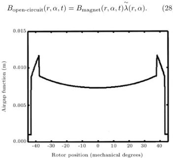
Figure1. Approximate airgap function.
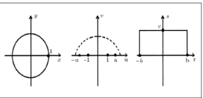
Figure 2. z-w- andt-planes in the conformal
transformations.
Composition of the two above mappings is equal to: t=ToW(x;y) =
u(x;y)+Z jv(x;y) 0
d p
(1 2)(1 k22) :
(4) If the position of a permanent-magnet edge in the rotor is given by curveC, the transformation maps curveC onto curveC
0, so that; C
( x=m
mtan()<y<+mtan()
; (5)
C 0
8 > < > :
u(y) =
2y y2+(1 m)2 v(y) =
(1 m)2 y2
y2+(1 m)2
mtan()<y<+mtan()
: (6)
It is usually dicult to calculate the above related elliptic integrals. So, it is better to consider another analytic function that satises the Cauchy-Riemann equation, i.e.:
f(z) = log(z) = lnjzj+jarg(z): (7) The function, log(z), is not only continuous in domain D, but also, analytic in that domain, with the property:
d dz
log(z) = 1 z
6
= 0; (8)
where:
D=fzj:jzj>0; <arg(z)<g: (9) The transformation dened in Equation 7 is also a conformal mapping onD(see Appendix 1). The image of any point (x;y) in the z-plane is the point (u;v) in thew-plane, whose rectangular coordinates are dened, representatively, as follows:
u(x;y) = 12 ln(x2+y2);
Figure3. Cross section of the rotor of interior PM
synchronous motor.
According to Figure 3, the rst octave of circleC1 is transformed into lineL1, with the parametric represen-tation written in the following equation:
C1 (
x=Rricos() y=Rrisin()
; 0<<=4; (11) L1
(
u(x;y) = ln(Rri) v(x;y) =
; 0:0<<
4: (12) Also, segment line AD(C2) is transformed into curve L2, with the following parametric representations:
C2 (
x=m y=mtan()
; 0<<=4; (13) L2
(
u(x;y) = ln
m
cos(v)
0v(x;y)+2
: (14)
Here, angle2 is dened as angle\AOD. In addition, segment lineBC(C3) is transformed into curveL3, with the following parametric representations:
C3 (
x=m+hm y=(m+hm)tan()
; 0<<=4; (15) L3
(
u(x;y) = ln
cos(m+hvm) 0v(x;y)+1
: (16)
Here, angle1is dened as angle\BOC.
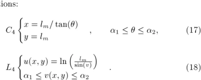
The segment line, DC(C4), is transformed into curve L4, with the following parametric
representa-tions: C4
(
x=lm=tan() y=lm
; 12; (17)
L4 (
u(x;y) = ln
lm
sin(v)
1v(x;y)2
: (18)
Following the above procedure for obtaining the trans-formed curves for the original lines and curves, the mapping of segment lines DE, EF and FC, as the domain of denition for the transformation, can be extended.
For the machine with parameters as shown in Ap-pendix 2 and using the above mentioned mapping, the image of the transformed domains, whose boundaries involve segment lines, half lines and curves, is shown in Figure 4. For every interval on thev-axis, the total airgap length for ux lines in the direction of theu-axis is dened as:
8 < :
G(u;v) = ln
m+hm m
0v1
; (19)
8 < :
G(u;v) =u4(v) ln
m
cos(v)
1v3
; (20)
8 < :
G(u;v) =u5(v) ln
m
cos(v)
3v2
; (21)
(
G(u;v) =u5(v) u6(v) 2v4
; (22)
Figure4. Mapping of the cross section of rotor of an
where functions u4(:),u5(:) andu6(:) are obtained by mapping the relations of segment lines CF, FE and ED. 3 and 4 can be dened in points F and E, respectively, by the following relations:
v at point F3;
v at point E4: (23)
Consequently, according to the above curve represen-tations for dierent inner rotor topologies, the airgap function can now be given as:
(v) =g0+Rri
exp
Gi(v)
exp
Gj(v) : (24) So, the new relative permeance function of the airgap that includes the eect of rotor saliency is, approxi-mately, equal to:
ROTOR-SALIENCY(;r)
r=rg=
0 ()
: (25)
In the above formula, 0=g0+
hm r
: (26)
Now, the transformed airgap function is shown in Figure 5.
The inuence of stator slots on the magnetic eld distribution in the airgap region can be successfully modeled using the following relative permeance func-tion [10]:
SLOT(;r)
r=rg =
1 X
n=0
n(rg)cos(nQs[+sa]): (27) The airgap ux density distribution obtained by these relative permeance functions can now be evaluated using:
Bopen-circuit(r;;t) =Bmagnet(r;;t)
(r;): (28)
Figure5. Modied airgap function prole.
SIMULATION RESULTS
For validation of the new proposed method, a fully-pitched, double-layer winding interior-type PM syn-chronous motor drive is considered. The motor is a 5HP, 1500rpm, 4-pole synchronous motor. Figure 6 shows ux lines at a rotor position, on the basis of a time-stepped transient nite elements analysis of the motor. The rotor and stator are of ferromagnetic materials, i.e. M-19 and M-36, respectively and the eld excitation consists of four PMs of the Nd-Fe-B(N33) type. A Lagrangian sliding interface path (surface) is also used to consider the eect of rotor mesh movement in a torque calculation process. The analysis is based on the transient electromagnetic nite element formulation with rotor motion (owchart of Figure 7). The airgap of the machine is divided into two layers. This two-layer airgap region is used and constraint equations are enforced between these two
Figure 6. A mesh used in torque analysis and ux lines
Figure7. Transient nite element method.
layers. The fundamental component of the ux den-sity distribution, obtained by transient nite element analysis, at time zero, is:
Bopen-circuit( r) = 0:6485cos(2[ r]): (29) And the one obtained by the new analytical method, without considering the buried airgap region, is, as follows:
Bopen-circuit( r) = 0:5717cos(2[ r]): (30) Also, the one obtained by the new analytical method, considering the barrier (buried airgap) region, is:
Bopen-circuit( r) = 0:5456cos(2[ r]): (31) Figures 8 to 18 show the ux density distribution in the mid-airgap region and back-EMF, obtained by FEM and analytical techniques. Figures 8 and 9 show ux density distribution and its spectrum obtained by FEM results. Figures 10 and 11 also show Back-EMF and its spectrum obtained by FEM results. In addition, Fig-ures 12 and 13 show the ux density distribution and its spectrum obtained by the new analytical method. Figures 14 and 15 show Back-EMF and its spectrum
Figure8. Flux density distribution. FEM results for
radial componanat of 8.
Figure9. Flux density distribution (FEM results).
Spectrum of ux density in mid-airgap.
Figure11. Back-EMF (FEM results); spectrum of EMF
of phase A.
Figure12. Flux density distribution; analytical results
for radial componant of B.
Figure13. Flux density distribution (analytical results);
spectrum of ux density im mid-airgap.
Figure 14. Back-EMF (analytical results) of phase A.
Figure 15. Back-EMF (analytical results); spectrum of
EMF of phase A.
obtained by the new analytical method. Figure 16 compares the ux density distribution obtained by FEM results at the mid-airgap region for both radial and tangential components. The spectrum comparison of the results of the FEM and analytical method for ux density distribution at the mid-airgap region are included in Figure 17. Figure 18 also shows the spectrum of the tangential component of ux density distribution at the mid-airgap region obtained by FEM results. By careful consideration of these gures, it is clear that there is an error of about 20 percent between the results of the FEM and the analytical methods; however, the calculation time for FEM is much greater than that of the new analytical technique.
For simplicity, one quarter of the machine has been modeled by FEM and required periodic boundary conditions are also considered as sets of constraint equations between nodes and elements. The analytical back-EMF calculation is calculated using the method
Figure16. Flux density distribution (FEM results).
Figure17. Comparison of ux density distribution at
mid-airgap region (radial component) for FEM results and analytical results.
Figure18. Flux density distribution (FEM results).
Tangential component at mid-airgap region.
Figure19. Measured back-EMF [7].
Figure20. Design model of IPM motor [7].
stated in Appendix 3. On the other hand, in the FEM calculations, at rst, the total ux-linkage of phase A is calculated instantaneously in one half period of a rotor revolution, as in the following equation and, then, the back-EMF is determined:
= NS
S lr
Z
Ads: (32)
Figure 19 shows the measured back-EMF waveform of a dierent IPM synchronous motor (Figure 20), with dierent stator-slot topology; when the rotor was driven under no-load by an external prime mover at a constant speed of 500 rpm. This IPM motor is developed and measured experimentally by Lee et al. [11]. Considering Figures 10, 14 and 19, the validity of the calculations of the analytical method can be seen.
CONCLUSION
The improved relative permanence model for the calcu-lation of space and time harmonics in load and no-load ux density distributions in the airgap of an interior-type permanent-magnet synchronous motor has been
proposed and validation of the analytical method is carried out by the conventional transient nite element method. The eect of stator slots, rotor saliency and magnet shapes can be considered in this model. Thus, this method can be used for those processes with intensive iterative calculations, such as shape and design optimization processes.
NOMENCLATURE
Bmagnet ux density due to magnet at stator inside surface
Bopen-circuit open-circuit ux density distribution b0 stator slot-opening
efA back-EMF of phase A p number of pole pairs Qs stator slot number rg mid-airgap radius
wS equivalent stator slot-opening wt stator tooth width
angular displacement between the stator mmf and rotor mmf
sa angular displacement between the stator slot axis and the axis of the coils of phase A
relative permeance function PM ux linkage due to the permanent
magnets
ref reference permeance
REFERENCES
1. Skvarenina, T.L., The Power Electronics Handbook, Purdue University, West Lafayette, Indiana, CRC Press (2002).
2. Meier, S., Theoretical Design of Surface-Mounted Permanent-Magnet Motors with Field-Weakening Ca-pability, Master Thesis, Royal Institute of Technology, Stockholm, Sweden (2002).
3. Jahns, T.M. and Soong, W.L. \Interior permanent-magnet synchronous motors for adjustable-speed drives",IEEE Transactions on Industry Applications,
IA-22(4), pp 738-747 (July/Aug. 1986).
4. Boldea, I., Reluctance Synchronous Machines &
Drives, Oxford University Press (1996).
5. Zhu, Z.Q., Howe, D. and Chan, C.C. \Improved analytical model for predicting the magnetic eld dis-tribution in brushless permanent-magnet machines",
IEEE Transactions on Magnetics,38(8), pp 1500-1506
(July 2002).
6. Boules, N. \Prediction of no-load ux density distri-bution in permanent magnet machines",IEEE Trans-actions on Industry Applications, IA-21, pp 633-643
(1985).
7. Boldea, I. and Nasar, S., The Induction Machine Handbook, chapters 12-14, CRC Press (2002).
8. Churchill, R.V., Brown, J.W. and Verhey, R.F., Com-plex Variables and Applications, McGraw-Hill, Fourth Edition (1990).
9. Kreyszig, E., Advanced Engineering Mathematics, John Wiley & Sons, Sixth Edition (1988).
10. Zhu, Z.Q. and Howe, D. \Instantaneous magnetic eld distribution in brushless permanent magnet DC motors, part III: Eect of stator slotting", IEEE Transactions on Magnetics, 29(1), pp 143-151 (Jan.
1993).
11. Lee, J.H., Kim, D.H. and Park, Il.H. \Minimization of higher back-EMF harmonics in permanent-magnet motor using shape design sensitivity with B-spline parameterization", IEEE Transactions on Magnetics,
39(3), pp 1269-1272 (May 2003).
12. Zhu, Z.Q., Howe, D., Bolte, E. and Ackermann, B. \Instantaneous magnetic eld distribution in brushless permanent magnet DC motors, part I: Open-circuit eld", IEEE Transactions on Magnetics, 29(1), pp
124-135 (January 1993).
13. Zhu, Z.Q. and Howe, D. \Instantaneous magnetic eld distribution in brushless permanent magnet DC motors, part VI: Magnetic eld on load",IEEE Trans-actions on Magnetics,29(1), pp 152-158 (Jan. 1993).
APPENDIX 1
Conformal Mapping
By writingf as follows:f(z) = log(z) = 12 ln(x
2+
y
2) +
jarctan y x : (A1) The transformation, w = log(z), maps the right half plane,x>0, onto the horizontal strip, I, i.e.,
I : =2<v<=2: (A2)
Theorem 1
A function, f(z) = u(x;y) +jv(x;y), is analytic in a domain, D, if, and only if, v is a harmonic conjugate ofu, i.e.,
uxx(x;y) +uyy(x;y) = 0;
vxx(x;y) +vyy(x;y) = 0:y (A3) It can easily be shown that the component functions, u and v, of log(z), Equation A1, satisfy the partial dierential Equations A3. So, this function is analytic on D.
Denition 1
The transformation, w = f(z), is called a conformal mapping atz0 if the value (magnitude) and direction (sense) of the angle of inclination of any two smooth arcs,C1 andC2, passing throughz0, are preserved. y
Theorem 2
The mapping, w = f(z), is conformal in D if f is analytic in D and its derivative, f
0
(z), has no zeros
there.y
Using Theorem 2 and Denition 1, it can be shown that transformation, w = f(z) = log(z), is a conformal mapping [8,9].
APPENDIX 2
Brushless PM Motor Parameters
Magnet arc angle (2m) 65 mechanical degrees
Magnet material Nd-Fe-B, N33
Relative recoil permeabilit (r) 1.05 Remanence (Bres) 1.1 Tesla Rotor lamination material M19,26 Gage Stator lamination material M36,26 Gage Stator outer radius (rso) 97.1 mm Stator slot opening (bo) 5.1 mm Stator tooth depth (ht) 17.2 mm Stator yoke depth (hy) 17.4 mm
APPENDIX 3
Back-EMF Calculations
The current and back-EMF are supposed as follows. The ux linking a stator coil is calculated from [12,13]:
=X
n
n
np
Kyncos(np); (A4)
where n and Kyn are dened in [12,13]. Therefore, the EMF induced at each turn of a coil is:
e1 turn(t) = d
dt
; (A5)
and the induced EMF at each phase is obtained as: ephase(t) =
X
n
!rnKynKwnNSsin(np); (A6) whereNsis the number of turns per phase andKwn(= Kd;n Kp;n Kskew;n) is the nth harmonic of the winding factor.