Implementing Pushback: Router-Based Defense Against DDoS Attacks
John Ioannidis
Steven M. Bellovin
[email protected]
[email protected]
AT&T Labs Research
AT&T Labs Research
Abstract
Pushback is a mechanism for defending against dis-tributed denial-of-service (DDoS) attacks. DDoS attacks are treated as a congestion-control problem, but because most such congestion is caused by malicious hosts not obey-ing traditional end-to-end congestion control, the problem must be handled by the routers. Functionality is added to each router to detect and preferentially drop packets that probably belong to an attack. Upstream routers are also notified to drop such packets (hence the term Pushback) in order that the router’s resources be used to route legitimate traffic. In this paper we present an architecture for Push-back, its implementation under FreeBSD, and suggestions for how such a system can be implemented in core routers.
1. Introduction
Distributed Denial of Service (DDoS) attacks have be-come an increasingly frequent disturbance of the global Internet[15]. They are very hard to defend against because they do not target specific vulnerabilities of systems, but rather the very fact that the target is connected to the net-work. All known DDoS attacks take advantage of the large number of hosts on the Internet that have poor or no se-curity; the perpetrators break into such hosts, install slave programs, and at the right time instruct thousands of these slave programs to attack a particular destination. The attack does not have to exploit a security hole at the target to cause a problem (although that would exacerbate the problem, to the attacker’s benefit), and there is almost nothing the vic-tim can do to protect itself.
Under normal operating conditions, and assuming that network links and router processing capacity have been ade-quately provisioned, the standard, TCP-like congestion con-trol ensures fair use of the available resources. Under a DDoS attack, the arriving packets do not obey end-to-end congestion control algorithms; rather, they incessantly bom-bard the victim, causing the well-behaved flows to back off and eventually starve. In addition, a large-scale DDoS at-tack not only causes trouble to its intended victim, but also
interferes with other traffic that may happen to share a por-tion of the network that is being heavily congested.
Mahajan et al. [13, 14] introduce a network-based solu-tion, called Pushback, to address the question of whether anything can be done inside the network to defend against DDoS attacks, and evaluate the solution with extensive sim-ulations. In this paper, we present an implementation of these concepts under Unix, along with experimental results from our laboratory testbed. In the rest of this section we give a very brief overview of the Pushback mechanism; the reader should refer to [14] for all the details. Section 2 presents the architecture of a router that can support Push-back; Section 3 gives implementation and performance de-tails; we conclude with a discussion of deployment options, as well as related work.
1.1. Overview of Pushback
If we could unequivocally detect packets belonging to an attack and drop just those, the DDoS problem would be solved. However, routers cannot tell with total certainty whether a packet actually belongs to a ‘good’ or a ‘bad’ flow; our goal will be to develop heuristics that try to iden-tify most of the bad packets, while trying not to interfere with the good ones. Again, Mahajan et al. introduce the concept of Aggregate-based Congestion Control (ACC); in this context, an aggregate is defined as a subset of the traf-fic with an identifiable property. For example, “packets to destinationD,” “TCP SYN packets,” or even “IP packets
with a bad checksum” are all descriptions of aggregates. The task is to identify aggregates responsible for conges-tion, and preferentially drop them at the routers.
To illustrate Pushback, consider the network in Fig-ure 1.1. The server D is under attack; the routersR
n are
the last few routers by which traffic reaches D. The thick lines show links through which attack traffic is flowing; the thin lines show links with no attack traffic. Only the last link is actually congested, as the inner part of the network is adequately provisioned. In the absence of any special mea-sures, hardly any non-attack traffic would be reaching the destination. Some non-attack traffic is flowing through the links between R2-R5, R3-R6, R5-R8, R6-R8, and from R8 to D, but most of it is dropped due to congestion in R8-D.
D R5 R6 R1 R2 R3 R7 R4 R8
Figure 1. A DDoS attack in progress.
Throughout this paper we shall be referring to ‘good,’ ‘bad,’ and ‘poor’ traffic and packets. Bad packets are those sent by the attackers. Bad traffic is characterized by an
at-tack signature, which we strive to identify; what can be
re-ally identified is the congestion signature, which is the set of properties of the aggregate identified as causing problems.
Poor traffic consists of packets that match the congestion
signature, but are not really part of an attack; they are just unlucky enough to have the same destination, or some other properties that cause them to be identified as belonging to the attack. Good traffic does not match the congestion sig-nature, but shares links with the bad traffic and may thus suffer. Whether traffic is considered ‘good,’ ‘bad,’ or ‘poor’ (or simply unaffected) depends on the congestion signature employed; in the examples that follow, the congestion sig-nature will be “UDP traffic destined for D.”
Good traffic in Figure 1.1 is, for example, TCP traffic entering from any of the links on top and destined for D; because the link R8-D is congested, that traffic suffers. If the link R2-R5 were also congested, traffic exiting from the lower-left link of R5 might also suffer: according to our definition, this would still constitute ‘good’ traffic (it goes through a link congested by the attack); the term “collateral damage” has been used to describe it, in order to empha-size that such traffic is not going to the target of the attack. One of the benefits of Pushback, that no other mechanism offers, is the ability to prevent such collateral damage from happening. Returning to the example, some of the traffic entering R4 is good (non-UDP traffic destined for D), some is poor (legitimate UDP traffic to D), and some is simply unaffected (the fraction of traffic exiting R7 that is not go-ing to R8), but none is bad (there is no attack comgo-ing in from that subtree). Traffic entering from R1 through R3 is a mixture of all four kinds of traffic. Now, no matter how smart filters R8 could employ, it cannot do anything to al-low more good or poor traffic originating from the left side of the graph to reachD. All it can do is preferentially drop
traffic arriving from R5 and R6, hoping that more non-bad traffic would flow in from R7. With Pushback, R8 sends messages to R5 and R6 telling them to rate-limit traffic for D. Even though the links downstream from R5 and R6 are not congested, when packets arrive at R8 they are going to be dropped anyway, so they may as well be dropped at R5 and R6. These two routers, in turn, propagate the request up to R1, R2, and R3, telling them to rate-limit the bad traf-fic, allowing some of the poor traftraf-fic, and more of the good traffic, to flow through.
2. Architecture
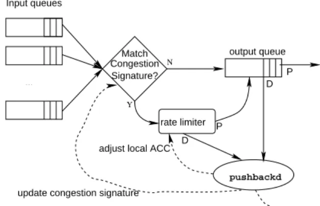
Consider a typical router; Figure 2 gives the view of the routing mechanism from one output interface. There are several incoming links, and the routing subsystem is implic-itly shown in the choice of the output interface. A rate lim-iter is introduced before the output queue. In the FreeBSD operating system [8], the IPFW firewall package also does traffic shaping and is in fact used in our prototype as the rate limiter. Some form of rate limiting or traffic shap-ing is already in place in many commercial routers, so this approach is not restricted to Unix-based routers only The simplest way to view the rate limiter is as a predicate that decides whether a packet is dropped or forwarded. In our architecture, dropped packets are sent to the Pushback dae-mon,pushbackd. The daemon, in turn, periodically up-dates the parameters of the rate limiter, and also informs the upstream daemons to update theirs. It is interesting to point out that the actual Pushback daemon may not reside on the router itself, but rather on an external ancillary piece of equipment. N . . . pushbackd rate limiter output queue Input queues Signature? Match Congestion
adjust local ACC D P
D P
pushback update congestion signature
Y
Figure 2. Partial view of a router.
Packets that are not dropped by the rate limiter are sent to the output queue, and may be dropped then if there is no available bandwidth for them to be transmitted. This has the (desired) effect that packets that matched the congestion signature but were not dropped by the rate limiter are not treated preferentially over packets that did not.
The Pushback daemon receives dropped packets from both the rate limiter and the output queue, as it needs to know both how well the rate limiter is performing and how many other packets are still being dropped in the output queue. The information sent to the Pushback daemon is shown in Figure 2. Most of the fields have the obvious pur-pose. The magic number provides some protection against synchronization problems between the kernel and the user-level process. The timestamp is expressed in nanoseconds since the router was last booted, and its purpose, along with the packet size, is to allow the code to estimate the bandwidth that would have been consumed by the dropped packets. The ‘reason’ field indicates whether this was a rate-limiter drop or an output queue drop, and if the lat-ter, whether it was a tail-queue drop, a RED drop, and so on. Only packets dropped because of queue discipline re-strictions are logged; packets dropped because, for exam-ple, they were not routable, or even because no buffer space could be allocated for them at the driver may not even reach this part of the code, so they are not reported at all. This is the desired behavior, as these other packets would not have left the router anyway and thus would not have affected the congestion of downstream links.
Magic number IP Destination address Input interface Output interface Timestamp Packet size Reason
Figure 3. Dropped packet report.
It is important to note that the design decision to separate the rate-limiting and packet-dropping functionality from the rest of the Pushback mechanism has implications for the eventual deployment of such a mechanism in the Inter-net. Routers can be designed1to report information about dropped packets, either to a process running on the router CPU, or on a computer attached to the router using a local interface. All the intelligence, which would have to evolve rapidly as DDoS attacks change in nature, would reside in easy to replace, generic PCs, and scarce router resources do not have to be allocated to the Pushback task.
2.1. Aggregate Detection
Periodically,pushbackdprocesses the saved drop set (i.e., the set of packets dropped by the rate limiter and the output queue) to try to detect congestion. A large amount of dropped packets obviously indicates congestion. If the rate limiter has not been engaged yet, and all dropped packets
1in fact, some high-end routers already do that.
are coming from the output queue, congestion exists on the link between this router and the next. If all drops are the work of the rate limiter, this could indicate that rate-limiting is working too well, perhaps the limits should be reduced.
The Pushback daemon now has to determine if there is an attack going on, and whether to respond to it. The exact algorithm(s) to run are will be an important research topic for some time to come. We present such an algorithm here; another can be found in [14].
We start by considering the drop set, that is, the set of packets that are dropped by the rate limiter. These may include packets dropped because of already-existing Push-back activity, but as we shall see, this does not affect the outcome of the algorithm. The size of the drop set should be large enough to allow meaningful results, but also small enough to be processed in a small amount of time. Fortu-nately, it is not necessary to keep all the dropped packets; a representative sample of them suffices, as it is the most fre-quent packets that will affect the outcome of the algorithm, and these will be the most represented ones in the sample. The important feature is that the algorithm should run in less time that it takes to collect the packets.
This algorithm detects aggregates based only on IP desti-nation address; the assumptions (the most pessimistic pos-sible) are that source addresses cannot be trusted anyway, and that the attackers are just sending IP packets with ran-dom contents to attempt to congest the target link. It starts by deciding whether the congestion level is high enough, that is, the drop rate is high enough, to warrant attempt-ing to do preferential droppattempt-ing. A simple test is whether the bandwidthw
oof the output link would be exceeded by
more than an acceptable drop rate, say, 20% of the traffic, in other words, ifw
i
>1:2w o, where
w
iis the total
incom-ing bandwidth from all input links. If this is the case, the algorithm starts by matching the destination address of each dropped packet against the routing table, and selecting the longest matching prefix. This groups the dropped packets according to their eventual destination link in some down-stream router (or even the target, if the target has multiple IP addresses). The drop set is then sorted with the prefix as the key. We now want to find the prefix with the highest count. This can be done in a single pass. The sorting has complexityO(nlogn), wherenis the size of the drop set.
The counting and determination of the most frequent prefix is, of course, linear inn. Now, for the subset of the drop set
that matches this selected prefix, we perform another scan to see if the destinations of the dropped packets match a longer prefix than the routing prefix. If, for example, a single ma-chine has been targeted, even though the prefix garnered from the routing table will be shorter than 32 (or 128, in the case of IPv6) bits, the address of the selected aggregate will be the full 32 (or 128) bits. The selected prefix consti-tutes the congestion signature; we denote the bandwidth for
which this traffic is responsible asw b.
It is likely that more than one attack is happening at the same time. If removing the traffic identified the congestion signature does not bring the output traffic below the pre-viously described acceptable level, that is, if w
i w
b > 1:2w
ostill holds, the algorithm is repeated in the hope of
adding more prefixes to the congestion signatures. The pre-cise parameters would be tunable to specific installations.
In some case we may not be able to find a second pre-fix (or even a first) responsible for a significant fraction of the traffic; that would be the case where congestion is not caused by an attack, or traffic to a specific destination, but by a general increase in background traffic. We then rate-limit what we can, and let the queue management of the output link, whatever it is, handle the rest of the congestion. It is also possible to run multiple detection algorithms concurrently, each looking for different properties; for ex-ample, it may be desirable to detect both random traffic and particular kinds of attack such as a TCP SYN attack. In that case, two congestion signatures are given to the rate limiter, and packets matching either signature are dropped.
2.2. Rate Limiting
Once the congestion signature has been identified, the code must decide what to rate-limit it to. Ifw
b >w l, where w l =w i 1:2w
o, then we simply rate-limit the aggregate
down tow
l, and pass the rest of the traffic on. If w
b <w
l,
we eliminate all traffic belonging to the congestion signa-ture, and let the rest of the excess traffic be limited by the output queue. Also, remember that the traffic that passes through the rate limiter and is not dropped is not treated preferentially; it is also sent to the output queue of the inter-face and treated just like the rest of the output traffic. That is, just because a packet was not dropped by the rate limiter does not mean that it will be preferentially treated and not dropped if it must at the output queue.
The Pushback daemon gets dropped packets from both the rate limiter and the output queue; if the rate of the at-tack stays constant, the daemon will get the same number of dropped packets, but it will be getting more of them from the rate limiter. This means that, as long as the attack is go-ing on, the Pushback daemon will keep tellgo-ing the rate lim-iter to drop packets; when it stops, no special action needs to be taken; at the next update, no attack will be identified, and the rate limiting will stop. Naturally, some damping may be necessary to avoid oscillations; experience with these mech-anisms in production networks will be necessary before all the details can be worked out.
2.3. Pushback
So far we have described the local version of ACC. This is not enough, however. Once the Pushback daemon has iden-tified a prefix to rate-limit, it communicates that information
to its upstream links. The messages exchanged by routers implementing Pushback are described in detail in [10]. The most important message is the Pushback Request, shown in Figure 2.3.
Various header fields RLS-ID
Maximum depth
Depth of Requesting Node Bandwidth Limit
Expiration Time Congestion Signature
Figure 4. Pushback Request.
Each request has a Rate-Limiting Session Identifier (RLS-ID), which is used to match responses (status mes-sages, described later) to requests. The Depth field is used to set a limit to the propagation of the Pushback requests. The depth of the originator is 0; whenever a Pushback mon receives a request, it passes it on to its upstream dae-mons, adding 1 to the depth before propagating the mes-sage. The maximum depth of propagation is set by the orig-inating router and passed along by each subsequent router. Pushback uses soft state; there is no explicit revocation of a Pushback request, and no effort is made to recapture the state after a router reset. The expiration time is used to man-age this soft state – if a Refresh messman-age does not arrive before the expiration time has elapsed, the entry is deleted. Finally, the congestion signature is a list of destination pre-fixes that the bandwidth limit applies to.
Authentication of Pushback requests is an obvious con-cern. If the routers participating in Pushback are neighbors, simply sending the request out with a TTL (or hop count for IPv6) of 255 is sufficient; any request coming from an attacker would have a lower TTL, and if an attacker has compromised a router, there are more serious concerns to be resolved. While ordinary authentication mechanisms such as IPsec can be used, it is not necessary to do so in the case of adjacent routers under common administrative control.
A special type of request is a cancel message, which in-structs the upstream router to stop rate-limiting. It is useful when long expiration times are specified by default, and the originating router has decided that it no longer needs pro-tection from upstream.
The Pushback daemon not only sends requests, but it also listens for requests from its downstream routers. Once it receives a Pushback request (or refresh), it adds the appro-priate rule to the rate limiter, and keeps track of the dropped packets it gets from it.
In addition to requests sent upstream, the Pushback dae-mon also sends status messages downstream. These sta-tus messages contain a depth field; if it is non-zero, the
response is simply passed along downstream (remember that Pushback request messages are passed only between adjacent routers, possibly using non-globally-routable ad-dresses; hence, the status messages have to follow the same hop-by-hop paths). Since many Pushback operations may be happening at the same time, the downstream direction for any particular one can be determined by examining the local set to match the congestion signature and RLS-ID, and determine which interface it pertains to. Before propagating a request downstream, 1 is subtracted from the node depth.
When a daemon receives a response (with depth 0), it can use the information in it to determine whether to continue the Pushback, or how to modify it. For example, it may determine that a larger fraction of traffic that was was re-quested is being dropped on the subtree upstream from one link, and much less traffic from the subtrees upstream from the rest of the links. Such information may be used to dy-namically adapt the requests to match the evolving traffic patterns.
In the following section, we describe how this architec-ture is actually implemented under FreeBSD.
3. Implementation
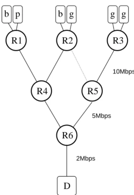
Encouraged by the simulation results in [14, 13], we im-plemented Pushback under FreeBSD. The tests were carried out on the network shown in Figure 3.
R1
g
R2
R4
R3
D
p
R5
b
g
R6
g
b
10Mbps 5Mbps 2MbpsFigure 5. Testbed network.
The sources of bad (attack), poor (legitimate but sharing a congestion signature), and good (legitimate but suffering) traffic are shown as b, p, and g, respectively. The destina-tion of all traffic is the subnet where D is connected, but only D is under attack. Rn are routers; the links between the
routers are 10Mbps for the first layer, 5Mbps for next layer, and 2Mbps between the last router and the destination. The test hardware being used (300MHz PentiumII generic PCs with 100Mbps Ethernet interfaces, running FreeBSD 4.2) can easily route at least 30Mbps of aggregate traffic with-out dropping any packets; in our experiments, substantially slower rates were used, both to give a margin of safety, and to make the actual measurements easier.
We use the IPFW packet filter functionality present in FreeBSD to both simulate links of particular bandwidth-delay characteristics, and to implement the rate limiter for the actual Pushback operations. For, example the following two commands specify that the link outgoing on interface xl2 has a bandwidth of 10 megabits per second, and its queue can hold 50 packets (which is the usual queue length of Ethernet interfaces).
# ipfw add 999 pipe 999 ip from any to any out xmit xl2
# ipfw pipe 999
config bw 10Mbits/s queue 50packets
The link speeds are configured by setting up the output speeds of the corresponding interfaces. No input speeds need to be configured. The rate limiting code in IPFW may apply various queue disciplines, such as RED; the default discipline is tail-drop, and it is what is used in our experi-ments.
The kernel has been modified so that when a packet is dropped in the queue management code, the information described in Figure 2 is sent topushbackd. Any num-ber of mechanisms can be used to pass information from the kernel to the user; we chose to use the tunnel interface driver (tun(4)). When the output routine of the tunnel driver (tunoutput()) is called by the networking code in the kernel, the packet can be read from the user level by reading the corresponding/dev/tunn device. We use /dev/tun63. The user-level daemon,pushbackd, may keep only a sample of the dropped packets. The probability of keeping a packet is inversely proportional to its size, so that a constant fraction of the bandwidth, rather than of the packet count, is kept. At the traffic levels in the experiment, the code has no trouble keeping up. Pushbackdsamples the dropped packets it receives, and periodically (every 60 seconds) runs the aggregate-detection algorithm described in Section 2.1. Even for a drop set of10
5
packets, the algo-rithm runs in well under a second.
For each prefix that the daemon is rate-limiting, whether it is because of locally-detected congestion, or because of a Pushback request, it keeps an entry with all the fields shown in Figure 2.3, plus a starting time, in a linked list, ordered by
expiration time. As an implementation optimization, only the difference between expiration times is kept in the cor-responding fields, so that for each clock tick, only the first one has to be decremented. When the detection algorithm finds a prefix to rate-limit, it searches the list; if it is already there, and it is a prefix that was originated with the current node, it updates the expiration time, potentially moving it further back in the linked list.
When R6 detects congestion on its outgoing link to D, it runs the aggregate-detection algorithm, and decides that the target is 10.102.0.31 (the IP address of D). It then examines the traffic for D it is getting from R4 and R5, and it finds that R4 is sending it 5Mbps, but no traffic for D is arriving from R5 (the ‘g’ traffic coming in from R3 is for another host in D’s subnet). The outgoing link is only 2Mbps, it is going to request R4 to limit the traffic they are sending to 2.4Mbps (20% more than the output rate, so that some traffic. When this happens R4 inserts a firewall rule such as this:
# ipfw add 101 pipe 101 ip from any to 10.102.0.31/32 out xmit xl2
# ipfw pipe 101 config bw 2400Kbps Since there is no traffic coming in from R5 for D, no Pushback is sent to R5. Note that already we have a bet-ter situation; only 2.4Mbps are arriving from R4; therefore, if the ‘g’ sources upstream from R5 are sending traffic com-parable to that, more of it will get through than before R4 starts rate-limiting. However, this could have been accom-plished by clever input filtering on R6, so let us proceed one step further.
R4 will now tell R1 and R2 to rate-limit traffic to D. In a similar fashion, more of the bad traffic from the ‘b’ sources entering each of R1 and R2 will be dropped, and some of the traffic from the ‘g’ (good) sources destined for D’s subnet makes it through. Initial measurements indicate that Push-back is rate-limiting successfully, so that more good traffic is getting through. Further study is needed to fine-tune the sampling rates, detection intervals, and also consider feed-back information in adjusting the Pushfeed-back parameters.
It was no surprise that the system worked. The most in-teresting observation is that even though the hardware used is fairly old (a benefit in this case, as it is more easily over-loaded), there was no noticeable system performance degra-dation. This also does not come as a surprise, since all the switching in the kernel is done in software and in the same address space. In a real router with hardware-assisted fast switching paths for the common cases, the overhead of imposing a number of rate limiting sessions may be much higher.
4. Related Work
Distributed Denial of Service attacks have been a real problem for less than three years, and not much published work exists on the subject. Related work falls into two cat-egories: old work that can also be used in countering DDoS attacks, and new work specifically aimed at this task.
Originally, it was suggested that DDoS attacks could be countered by applying resource allocation techniques on network bandwidth. Integrated Services [5] and Differen-tiated Services [2] are two approaches aimed at isolating flows with specific quality of service (QoS) requirements from lower-priority traffic. It is not clear if this approach would help; Web traffic, which is a significant fraction of network traffic, is likely to remain best-effort, so it will not be protected by QoS requirements. It is also not clear to what extent compromised sources could fake traffic to show it belonged to QoS-protected flows.
There are many congestion-control mechanisms, which, if only they were globally deployed, might alleviate some of the effects of congestion due to DDoS attacks. Random Early Detect (RED)[11] and its variants try to identify flows that do not obey TCP-friendly end-to-end congestion con-trol, and preferentially drop them. There is also a large body of work (e.g., Fair Queuing[7], Class-Based Queuing[12]) aimed at allocating specific fractions of the available band-width to each flow so that they all get served. The main problem with these approaches is that packets belonging to DDoS attacks do not have readily-identifiable flow signa-tures, and thus cannot be identified by these mechanisms. This is the reason why the concept of Aggregate-based Con-gestion Control was developed[14] and which is where the work in the present paper is based upon.
A different style of approach to combating DDoS attacks focuses on trying to detect a DDoS attack in progress and then respond to the specific attack. Various forms of packet tracking have been suggested. Some try to construct a par-tial map of the paths that the attack is taking; the two main variants are traceback [1] and packet marking [16, 6]. Oth-ers, such as [18] require all edge routers to log (a sample of all) packets, and then analyze the logs in order to identify, and hopefully block, sources of the attack. An interesting approach is that of [3] where, starting with a partial map of the network, they can locate routers where attack traf-fic is passing through by flooding them and watching the attack traffic decrease; while intellectually appealing, this technique is likely to create much controversy if it were to be applied routinely. In traceback techniques, routers pick outgoing packets with a small probability (e.g. 1=20000),
and send a traceback packet (a new kind of ICMP packet) to the same destination as the sampled packet. The trace-back packet contains the IP address of the router sending it, and is always sent out with a TTL (or Hop Limit) of 255 (as a rudimentary form of authentication). During an attack, a
sufficient number of these packets will reach the target for it to form an approximate map of the path the attack is taking. Of course, the attacker can inject its own traceback pack-ets, but unless it has compromised a router fairly close to the target (to inject packets with a sufficiently high TTL), all it will achieve is create a fictitious subtree from where part of the attack may be originating. Packet marking does not send additional packets, but rather modifies the IP ID field in each packet to carry partial information about the router that marked the packet. Clever techniques are used to reconstruct the original data. This approach has its own set of failures (e.g., it is hard to get it to work with IPv6). The question of what to do even when the paths the attack is taking are identified remains largely unanswered, and it may still involve human operators, especially when admin-istrative boundaries are crossed.
The common problem that all the tracking techniques are trying to solve is that source addresses in attack packets can-not be trusted, because they are very easy to forge. If all edge routers in the entire Internet were implementing source address filtering[9], this task would be greatly simplified. Of course, most machines where the packets are originating have been compromised by an attacker, and their owners do not even know that they are being used for an attack. More-over, even if the hundreds or thousands of machines that an attack is coming from were known, it is not clear what could be done about them. It has also been suggested[17] that in-trusion detection systems or firewalls be used to detect an at-tack in progress, and notify upstream elements accordingly. Finally, there is an approach that is similar to Pushback that was described in [19] in an Active-Networks-based defense against flooding attacks.
5. Discussion
Let us discuss some issues that may affect the way Push-back could be deployed. First off, it is fairly obvious that the Pushback approach is most effective when an attack is non-isotropic; in other words, when there are routers fairly close to the target where most of the attack traffic is arriving from a subset of the input links. That is a reasonably safe assumption; even the largest attacks do not involve more than a few thousand compromised machines, and there are many millions of machine on the Internet. It would be par-ticularly hard for an attacker to ensure that the attack slaves are evenly distributed with respect to the target.
Another issue to examine is what fraction of the attack traffic originates from hosts served by the same ISP as the target. The smaller the ISP, the smaller that fraction will be, and even the largest of the top-tier ISPs will have a sizeable fraction of attacks originating from the outside. While an ISP can unilaterally deploy Pushback in its routers, unless agreements with its peering ISPs are made on how to honor pushback requests (an issue fraught with security and policy
issues), said ISP will have to take advantage of Pushback as best as it can inside its own network. One easy step, which effectively extends Pushback by one more hop without the co¨operation of the upstream (belonging to a different ISP) router, is to perform input rate-limiting on the border routers (along with the normal output rate-limiting). Of course, this is only useful if the border router connects to more than one other border routers. Applying input rate-limiting penalizes bad traffic coming in on the rate-limited input link without affecting incoming traffic from other links (which output-only rate-limiting would). Conceptually, this is the same as the border router having one additional router between itself and each peering link, and sending pushback requests to those conceptual routers.
Now, in general, an ISP’s network can be thought of as a cloud where clients attach (on edge routers) and which con-nects to other ISPs at peering points (private or public). An ISP’s network can thus be viewed as a single virtual router, with multiple inputs and multiple outputs. If, in addition to output rate limiting, we were to implement input rate limit-ing, then the following variation of Pushback could be con-sidered: when an edge router detects an attack toward one of its attached customers, it tries to determine what frac-tions of the attack traffic are coming through the border routers of the ISP. This could be done with some variation of ITRACE or packet-marking by the border routers that would be caught and examined at the edge routers. The edge routers would then ask (with proper authentication, of course) the border routers to apply input rate limiting to the requested aggregate.
The detection algorithms in the Pushback architecture are not necessarily limited to information they get from just the drop set. Rather, Pushback should be viewed as com-plementary to many of the DDoS detection approaches de-scribed in Section 4. For example, the drop set can be com-pared with information gathered with ITRACE in an effort to adjust the congestion signature so as to reduce the amount of traffic being penalized (‘poor’ and ‘good’ traffic). More-over, a good map of the network with reliable historical traffic profiles from traces can be used to determine sud-den changes in traffic profiles that could signal an attack, or help determine how to best allocate rate limits in pushback messages.
6. Summary and Future Work
We presented the implementation of a mechanism that treats Distributed Denial of Service attacks as a congestion-control problem, and acts by identifying and preferentially dropping traffic aggregates responsible for such congestion. The purpose of this work is twofold; to show the practical-ity of such an approach, and to explore ways of deploying it incrementally in an operational environment. We already know from simulations[14] that Pushback is a promising
way of combating DDoS attacks and flash crowds. There are some aspects that are easy to simulate, but real code running on real machines allows us to explore the details of a real system. We also needed to see how much memory and computing power is needed to actually run Pushback, in the hope of influencing commercial router designers toward implementing Pushback in their code. A promising hybrid solution, which we plan to investigate over the next few months, is to use features such as the Committed Access Rate[4] in ciscoR
routers to implement the rate-limiting, while sniffing traffic on both incoming and outgoing links of each router to detect congestion and dropped packets, even if the router itself cannot report those. Such experi-ments may allow rapid deployment of Pushback even in the absence of explicit support from router vendors.
Acknowledgments
The original idea for Pushback came from an informal DDoS research group consisting of Steven M. Bellovin, Matt Blaze, Bill Cheswick, Cory Cohen, Jon David, Jim Duncan, Jim Ellis, Paul Ferguson, John Ioannidis, Marcus Leech, Perry Metzger, Robert Stone, Vern Paxson, Ed Viel-metti, and Wietse Venema. A recent paper [14] presents the theoretical basis and detailed simulation results upon which this work has been based. We also thank the anonymous reviewers for many valuable and insightful comments.
References
[1] S. M. Bellovin. ICMP Traceback Messages. Work in Progress, Internet Draft draft-bellovin-itrace-00.txt, March 2000.
[2] S. Blake, D. L. Black, M. A. Carlson, E. Davies, Z. Wang, and W. Weiss. An Architecture for Differentiated Services. RFC 2475, December 1998.
[3] H. Burch and B. Cheswick. Tracing Anonymous Packets to Their Approximate Source. In Usenix LISA, December 2000.
[4] Cisco Web Pages: Committed Access Rate. http://www.cisco.com / univercd / cc / td / doc / prod-uct / software / ios111 / cc111 / car.htm, February 1998. [5] D. D. Clark, S. Shenker, and L. Zhang. Supporting
Real-Time Applications in an Integrated Services Packet Network Architecture and Mechanism. In ACM SIGCOMM, 1992.
[6] D. Dean, M. Franklin, and A. Stubblefield. An Algebraic Approach to IP Traceback. In Proceedings of NDSS ’01, February 2001.
[7] A. Demers, S. Keshav, and S. Shenker. Analysis and Simu-lation of a Fair Queueing Algorithm. In ACM SIGCOMM, 1989.
[8] The FreeBSD Project. http://www.freebsd.org.
[9] P. Ferguson and D. Senie. Network Ingress Filtering: De-feating Denial of Service Attacks which employ IP Source Address Spoofing. RFC 2267, January 1998.
[10] S. Floyd, S. Bellovin, J. Ioannidis, K. Kompella, R. Maha-jan, and V. Paxson. Pushback Messages for Controlling Ag-gregates in the Network. Internet Draft, work in progress. [11] S. Floyd and V. Jacobson. Random Early Detection
gate-ways for Congestion Avoidance. IEEE/ACM Transactions
on Networking, Vol. 1(4):pp. 397–413, August 1993.
[12] S. Floyd and V. Jacobson. Link-sharing and Resource Man-agement Models for Packet Networks. IEEE/ACM
Transac-tions on Networking, Vol. 3(4):pp. 365–386, August 1995.
[13] R. Mahajan, S. M. Bellovin, S. Floyd, J. Ioannidis, V. Pax-son, and S. Shenker. Controlling High Bandwidth Aggre-gates in the Network. Submitted to Computer Communica-tions Review.
[14] R. Mahajan, S. M. Bellovin, S. Floyd, J. Ioannidis, V. Paxson, and S. Shenker. Controlling High Band-width Aggregates in the Network – Extended Version.
http://www.aciri.org/pushback/.
[15] D. Moore, G. M. Voelker, and S. Savage. Inferring Internet Denial-of-Service Activity. In 10th Usenix Security
Sympo-sium, August 2001.
[16] S. Savage, D. Wetherall, A. Karlin, and T. Anderson. Practi-cal Network Support for IP Traceback. In ACM SIGCOMM, August 2000.
[17] D. Schnackenberg, K. Djahandari, and D. Sterne. Infrastructure for intrustion detection and response. In Proceedings of the DARPA Information Surviv-ability Conference and Exposition 2000, March 2000. ftp://ftp.tislabs.com/pub/IDIP/DISCEX IDR-Infrastructure.pdf.
[18] R. Stone. CenterTrack: An IP Overlay Network for Track-ing DoS Floods. In 9th Usenix Security Symposium, August 2000.
[19] V. C. Van. A Defense Against Address Spoofing Using Ac-tive Networks. Batchelor’s Thesis, MIT, 1997.
![OER State Policy Playbook [DRAFT]](data:image/gif;base64,R0lGODlhAQABAIAAAP///wAAACH5BAEAAAAALAAAAAABAAEAAAICRAEAOw==)