International Journal of Research in Engineering & Applied Sciences
Email:- [email protected], http://www.euroasiapub.org
66
Implementation of Pipelined Out Of Order
Queue Processor Architecture
Noble G
M.Tech, VIT University, Tamil Nadu, India
Abstract:
In conventional processors, programs are executing in order and if there any dependency happen between the instructions, the execution needs to wait till the dependencies is over. It will reduce the performance and restricts the expression of parallelism in the program. In general, the instruction that can be executed simultaneously will perform separately.
Queue computing model provides excellent support for the existing processor designs. The instructions in the queue computing model, is not having any register expression part and hence there is no dependency as in above case. In addition to that, the elimination of register expression part makes the instruction length shorter and the programming can be done very easily. Most of the current processors are using complex hardware structure for register renaming and it can completely avoided in queue computing model
The efficiency of the processor can easily be improved by using pipelining. Queue processor will support all the facilities that are provided by the modern processor architectures. This paper describes the implementation of queue processor architecture along with pipelining and out of order execution and compares their performances.
Keywords:Queue Processor, Queue architecture, Out Of Order, Pipe lining, parallelarchitectures
I.
Introduction
Conventional processors are already performing one instruction per clock cycle and for improving the performance, the designers need to execute more than one instruction in the same clock cycle. This is achieved with the techniques like register renaming [1, 2] and dynamic scheduling. But the introduction of these technologies has an increased effect on power consumption, hardware complexity and it becomes a performance limiting factor. The designers are always challenged to develop processors with architectures that eliminate all the above problems and give much better performance. This is achieved with superscalar implementations of multiple thread processors. But increasing the units will need to provide continues independent inputs to those functional units. Unfortunately, most of the processors are not having this feature and the device utilization will be lesser than the expectation.
To develop a simple but fast processor leads us to queue architecture [3, 4, 5, 6]. It uses queues for intermediate storage of results instead of registers. Each of the instruction will take the required amount of data from the head of the queue or from an offset from the queue and the results will be stored back in the tail of the queue. The operation of the processors is based on Opcode, QH and QT values.
International Journal of Research in Engineering & Applied Sciences
Email:- [email protected], http://www.euroasiapub.org
67
The queue architecture is an exact remedy for the above problems. Here the programmer only needs to be familiar with the queue organization and can start to write the program very easily.
The PQP programs are based on breadth first traversal algorithm and hence it can achieve high instruction level parallelism. In addition to this, the PQP programs are very short since they do not need to specify the operands explicitly. The processor will always take the data either from the head or an offset from the head and calculated results will be stored back to the tail of the queue. It makes the instruction length shorter and hence the instruction memory can be saved. In addition to this, the PQP program instructions are free from false dependencies. This will avoids the necessity of register renaming in queue processors.
The performance of the system can be easily improved by using Out Of Order execution. It is an essential technique in all the current processors. The queue processor architecture highly supports the OOO execution since the data is taken implicitly by the processor itself.
The aim of this paper is to make a processor architecture based on queue architecture which highly supports out of order execution and compare the results with different processor implementations.
II.
Queue computing overview
The concept of queue is different from normal registers. A queue is an arrangement of registers with some specific restrictions and ordering sequence for accessing. In normal registers, it is possible to access data from anywhere and can be written to any location. That means data is randomly distributed in all over the architectural registers. The queue computing model uses a circular queue instead of random registers. Here the data is always taken from the head of the queue and results will be written back at the end of queue. It will have an improved effect in parallel execution, program compactness, hardware simplicity and high execution speed.
Breadth First Traversal
To obtain maximum level of parallelism in the program, breadth first traversal algorithm is used. It is a tree like structure having parent and child nodes and will starts from root node. From there, the program will explores to all the neighbouring nodes and again execution go to its child nodes till the last node is obtained. The diagrammatic representation of breadth first traversal is shown in figure. Execution starts from point A then moved to B, C, D and finally to E and F. In general, it moves top to bottom along with horizontal moves from left to right.
Fig.1 Graphical representation of Breadth first Traversal
Sample Program
A sample data flow graph for the expressions E = (A+B)*C and F = (CD)/ (A+B) is shown in figure 2. The operands are loaded with load instruction (ld), then computed with multiply, addition and division instructions. Store instruction is used to written back the results into data memory.
International Journal of Research in Engineering & Applied Sciences
Email:- [email protected], http://www.euroasiapub.org
68
highest to lowest levels. For complex programs having more number of instruction lines, it is better to make some compiler structure, which will automatically generate the assembly code [7, 8, 9, 10]. Otherwise the programmer needs to write the code with the help of a data flow graph [11, 12].
Fig.2 Sample data flow graph for the expressions E= (A+B)xCand F= CD/(A+B)
The generated instruction sequence from the graph is shown in Fig.3 and the content of the QREG at each execution stage is shown in Fig. 4
Load A //Load variable A
Load B //Load variable B
Load C //Load variable C
Load D //Load variable D
Add //Add QH and (QH+1) variables and stores result in QT
Mul // Multiply QH and (QH+1) variables and stores result in QT
Mul -2 // Multiply QH and (QH-2) variables and stores result in QT
Div -1 // Divide QH and (QH-1) variables and stores result in QT
St E //Store (A+B)xC into E location
St F //Store CD/(A+B) into F location
Fig.3 Instruction sequence
Queue Organization
International Journal of Research in Engineering & Applied Sciences
Email:- [email protected], http://www.euroasiapub.org
69
In the previous program we are using 4 loading instructions. It will load the operands A, B, C and D in parallel to the queue register as shown in the figure state 1. At this state QH and LQH pointers will point to the first data in the queue register, which means to A, and QT will points to the last empty location.
A B C D
CxD A+B D C (A+B)C CD/(A+B) LQH QH QT
LQH QH QT
QT LQH QH LQH QH QT State 1 State 2 State 3 State 4
Ld A, Ld B, Ld C, Ld D
Add, Mul
Mul -2, Div -1
St E, St F
Fig.4 Circular Queue Register content at each execution state.
International Journal of Research in Engineering & Applied Sciences
Email:- [email protected], http://www.euroasiapub.org
70
III. PQP CORE ARCHITECTURE
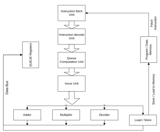
Instruction fetch Unit Instruction decode Unit Queue Computation Unit Issue Unit
Load / Store Devider Multiplier Adder Q U E U E R e g is te rs P ro g ra m / D a ta M e m o ry D a ta B u s S to re / L o a d t o M e m o ry F e tc h In s tr u c ti o n
Load to QUEUE Register
Fig. 5 PQP Core Architecture
Instruction Set
The instructions using in queue processor architecture is having 16 bit wide [13]. The first 8 bit is reserved for the Opcode and the remaining for offset representation. It is possible to represent a maximum of two offset in one instruction. To represent higher offset values, we can use the special instruction covop. It will extend store and load offset values of the instruction. Two bits are exclusively used for representing the sign offsets. General queue instructions are included in table 1 with description for each. Table 2 shows the opted instruction set format in queue architecture.
Table 1.General queue instructions
Class Instructions Description
Arithmetic and logic add, sub, div, mul, rsh, lsh, or
xor, and, not,rrot, lrot,
ALU instructions
Memory ld, st, ldi, lea
Load, Store, Load immediate value, Load effective address
Comparison ceq, cne, clt, cle, cgt, cge Comparison
Ctl. flow bt, bf, j Branch true, branch false, jump
Special dup,autlqh,stplqh Duplicates value of queue word
to QT
International Journal of Research in Engineering & Applied Sciences
Email:- [email protected], http://www.euroasiapub.org
71
Table 2.Instruction Set Format
IV.
DESIGN IMPLEMENTATION
To make a processor, which will be easily modifiable and supported for the industry application, the core is realised in Verilog HDL. The paper deals with 4 different implementation of queue architecture starting from basic queue core to advanced pipelined out of order core. Each implementation is synthesized and checked for the functional correctness with performance. Since the modular approach in the design, to add or remove instructions or particular functions, only the relevant parts needs to be modified.Basic instruction flow is given in figure 6.
NON PIPELINED QUEUE PROCESSOR
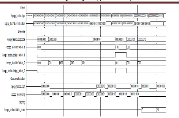
In non-pipelined processor, only one instruction will be issued at a time. During the issue time, all other units will be in off state. After fetching, the instruction will be given to the decode unit and it will decoded. Then the instruction will go to the queue section and finally execution and storing will happen. In general, only one operation will be performed at a time. The architectural view of the processor is given in figure 7.
The processor structure is realised in cadence using Verilog HDL and the physical view is given in figure 9. The output wave form is included in the figure 8.
Fig. 6 Basic flow of Instruction
Opcode(8 bit) Sign _1(1 bit) Offset_1(3 bit) Sign_2(1 bit) Offset_2(3 bit)
Instruction Decode Instruction
Fetch
Queue Calculation
Execution Write back
International Journal of Research in Engineering & Applied Sciences
International Journal of Research in Engineering & Applied Sciences
Email:- [email protected], http://www.euroasiapub.org
73
Fig. 8 PQP Processor without Pipelining outputFig. 9 Physical View of PQP Processor without Pipelining
PIPELINED QUEUE PROCESSOR
International Journal of Research in Engineering & Applied Sciences
Email:- [email protected], http://www.euroasiapub.org
74
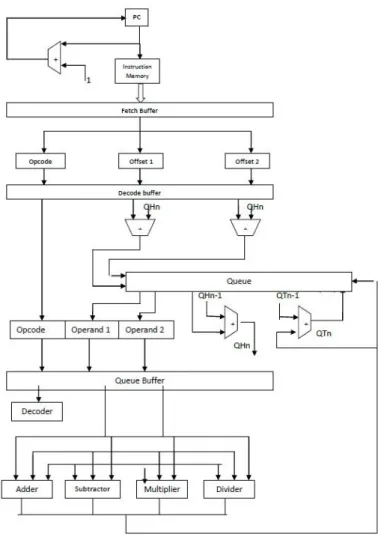
and fetching of the first instruction will do by the processor simultaneously. It is just opposite to the normal processor implementation where next instruction will start only after the finishing of previous instruction. In pipelining, different instructions are executing concurrently by different circuitry at the same time.
Here the total operation is divided into 5 stages. First unit will fetch instructions from the main memory. Then it will be given to the decoding unit. The decoding unit will decode all the instructions and issued to the execution unit. The operations will be performed at the execution unit and stores in the appropriate locations. For filling the pipeline queue, the processor will take 5 clock cycles initially. After that, we will get continues output. Output waveforms are shown in figures 10. Physical view is included in figure 12.
The processor is realised in cadence using Verilog HDL and the architecture is shown in Figure 11.
International Journal of Research in Engineering & Applied Sciences
Email:- [email protected], http://www.euroasiapub.org
75
Fig. 11 Pipelined Queue Processor ArchitectureInternational Journal of Research in Engineering & Applied Sciences
Email:- [email protected], http://www.euroasiapub.org
76
NON PIPELINED OUT OF ORDER QUEUE PROCESSOR
Out Of Order execution is an essential technique, in the area of processor architecture designs and was originated from the work by Tomasulo. The main idea of this algorithm is to make the programs execute by data flow order rather than the program order, and achieve higher level of instruction level parallelism along with a balanced load in functional units. Special circuitries were used to find out the dependencies between the instructions. This is achieved in normal processor with the help of a tag number. Each instruction will assign a separate tag number and then based on the availability of operands, issuing will occur. But in a queue architecture based implementation, this tag number insertion is not required. Here each instruction can know exactly its destination address and hence it can be executed in random order. This destination address is calculated at the queue computing section, which is before the issuing stage, with the help of queue tail value and number of produced data. Outputs of each instruction go directly to this location. Reservation stations are a speciality of out of order execution. All the decoded instructions were stored here along with the available operand. Each of such entry’s consisting of Opcode, operand values and queue tail value.
The instructions having all the operands will be issued to the corresponding functional units. A special circuitry, called scheduler is used for scheduling instructions to functional units. The functional units will perform the requested operation on the operands and results will put in the common data bus. It will transfer the result into the queue register pointed by the QT value. Along with this, the instructions requiring previous output will also be filled with corresponding value. When all the instructions in the reservation stations are issued, new instructions will be fetched and decoded from the instruction memory. The process will repeats till the end of the program. In general instructions are executed randomly by the functional units but shows an in order behaviour to the outside world.
International Journal of Research in Engineering & Applied Sciences
Email:- [email protected], http://www.euroasiapub.org
77
Fig. 13 Non Pipelined Out Of Order Queue Processor ArchitectureInternational Journal of Research in Engineering & Applied Sciences
Email:- [email protected], http://www.euroasiapub.org
78
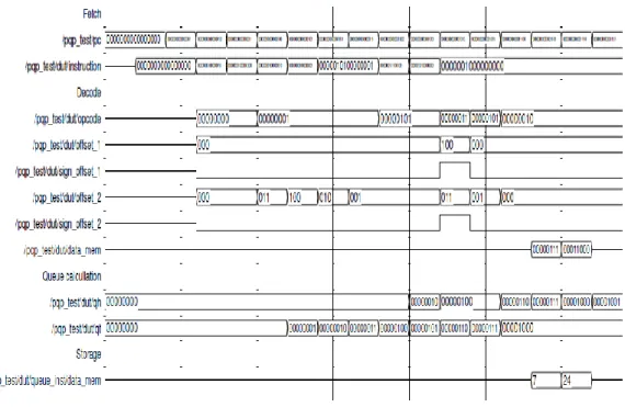
Fig. 14 Non Pipelined Out Of Order Processor outputPIPELINED OUT OF ORDER QUEUE PROCESSOR
International Journal of Research in Engineering & Applied Sciences
Email:- [email protected], http://www.euroasiapub.org
79
pipeline is the bigger problem for implementation. That means, a decoded instruction may require one of the operand that was not executed by the functional units. In order to solve this, the designers were implemented the technology of operand forwarding. Here the decoder is not need to wait for all the operands. The operands that were not available now will be forwarded back into the pipeline, when it becomes available, and hence the execution can continue without stalling.
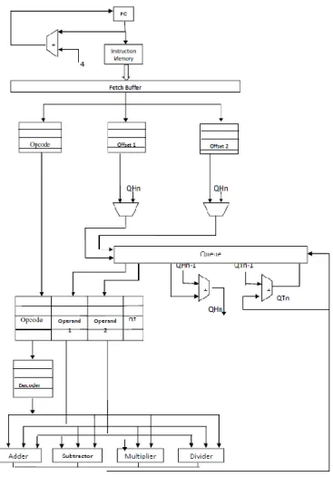
Pipelining can improve the performance of a system. It is possible to combine pipelining with out of order execution so that the performance become more better .The program counter is incremented by the order of four and fetching of four instructions will happen simultaneously. The number of instructions fetching together is depend on the total number of execution unit. For a processor with six separate execution unit, it is always better to fetch six instructions simultaneously. To get maximum utilization, all the fetched instructions should be different and are not depend on each other. In this condition all the instructions can be executed simultaneously. Related figures are shown in 16-18.
In addition to the operand queue, PQP is using instruction queues also. These queues will act as a reservation stations. So all the fetched instructions will come here and wait for it turns. If the operands of the second instructions are valid and if the functional unit is available, then corresponding instruction will be executed overriding by the previous one. The output of the result can directly store into the queue value defined by the Qt pointer.
International Journal of Research in Engineering & Applied Sciences
International Journal of Research in Engineering & Applied Sciences
Email:- [email protected], http://www.euroasiapub.org
81
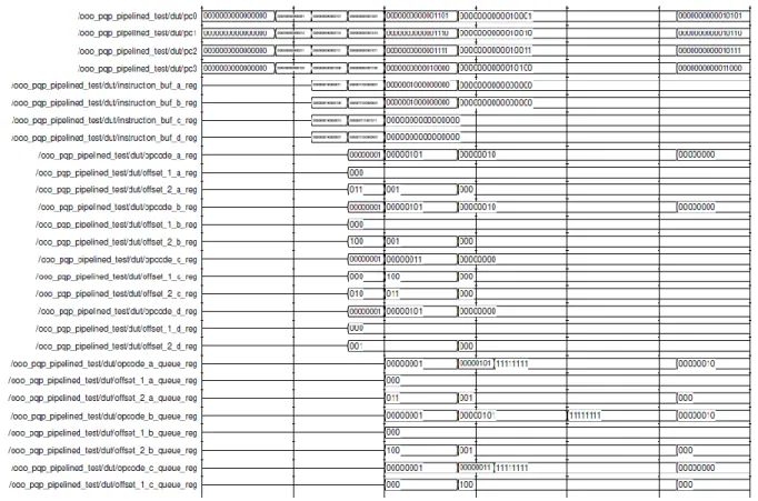
Fig. 17 Pipelined Out Of Order Processor outputV.
TIMING COMPARISON
The architectures were designed and the time taken for executing the sample program is given in table 3
Table 3.Timing Analysis
Instance Execution time (nS)
PQP 116
PQP_Pipelined 48
OOO_PQP 72
OOO_PQP_Pipelined 40
VI.
CONCLUSION
International Journal of Research in Engineering & Applied Sciences
Email:- [email protected], http://www.euroasiapub.org
82
The system performance can again be improved by using an out of order execution. It is an essential technique in all the current processors. The queue processor architecture highly supports the OOO execution since the data is taken implicitly by the processor itself. In addition to that the usage of Re Ordering Buffer in the Tomasalualgoritham can be completely avoided by queue architecture. It will help to achieve OOO execution with more performance and less hardware.
Designed processor cores for pipelined and non-pipelined PQP architecture along with out of order execution and compared the results in terms of timing. It is observed that pipelined out of order PQP architectures have high throughput than normal processors.
References
1. W.W. Hwu and Y.N. Patt, “Checkpoint Repair for Out-of-Order Execution Machines.”
Proceedings of the 14th Annual Symposium on Computer Architecture, (June 1987), pp. 18 26.
2. B. Bisshop, T. Killiher, M. Irwin, “The design of register renaming unit, in: VLSI1999”, IEEE
Proceedings of Great Lakes Symposium on VLSI, 1999, 208–216.
3. Ben A. Abderazek, ArquimedesCanedo, TsutomuYoshinaga, Masahiro Sowa, “The QC-2
parallel Queue processor architecture”,Journal of Parallel and Distributed Computing
,ELSEVIER (2008), 235– 245.
4. M. Arsenji, SoichiShigeta, Tsutomu Yoshinaga and Masahiro Sowa , Ben A. Abderazek,
“Queue Processor Architecture for Novel Queue Computing Paradigm Based on Produced
Order Scheme”, Proceedings of the Seventh International Conference on High Performance
Computing and Grid in Asia Pacific Region,IEEE Computer Society,134-142,2012.
5. M.Sowa, Ben A. Abderazek, T Yoshinaga, “Parallel queue Processor architecture based on
Produced Order Computation Model”The journal of supercomputing by Springer,32,217-229,
2005
6. B.A. Abderazek, T. Yoshinaga, M. Sowa, “High-level modeling and FPGA prototyping of
produced order parallel queue processor core”, J. Supercomputing 38 (1) (2006), pp. 3–15.
7. ArquimedesCanedo ,Ben A. Abderazek ,Masahiro Sowa “Compiling for Reduced Bit-Width
Queue Processors” journal of Signal Processing and Systems 59 (2010) 45-55.
8. Canedo, B.A. Abderazek, M. Sowa, “A GCC-based compiler for the queue register processor
(QRP-GCC)”, in: IWMST2006, The International Conference on Modern Science and
Technology, Wuhan, May 2006, pp. 250–255.
9. H. Schmit, B. Levine, B. Ylvisaker, “Queue machines: hardware compilation in hardware”,
10th Annual IEEE Symposium on Field- Programmable Custom Computing Machines, 2002, pp. 152–161.
10. S. K. Debray,W. Evans, R. Muth, and B. D. Sutter. “Compiler techniques for code compaction”.
ACM Transactions on Programming Languages and Systems, 22(2):378–415, 2000.
11. Maeda, A., and Nakanishi, “New Computation Model Queue Machine and Its Application to
Parallel functional Programming Languages”, 'Transaction of Information Processing Society
ofJapan, Vo1.38, No.3, pp.574-583( 2007.3).
12. Y. Okumura, T. Yoshinaga and M. Sowa. Parallel C compiler for queue machines. In IPSJ Symposium for Computer Architecture, 2(81):127–132, 2002.
13. B. A. Abderazek, S. Shigeta, T. Yoshinaga, and M. Sowa. Reduced Bit-Width Instruction Set
Architecture for Q-mode Execution in Hybrid Processor Architecture (FaRM-rq), IPSJ SIG TR,
pp. 19–23, June 2003.
14. J. Hiser, S. Carr, P. Sweany, and S. J. Beaty. “Register assignment for software pipelining with
partitioned register banks”, In Proceedings of the 14th International Symposium on Parallel
International Journal of Research in Engineering & Applied Sciences
Email:- [email protected], http://www.euroasiapub.org
83
15. M. G. Smelyanskiy, S. Tyson, and E. S. Davidson. “Register queues: a new
hardware/software approach to efficientsoftware pipelining “, In Proceedings of Parallel Architectures and Compilation Techniques, pages 3–12, 2000.
16. F. Arahata, O. Nishii, K. Uchiyama, N. Nakagawa,” Functional verification of the superscalar
SH-4 microprocessor”, The Proceedings of the International Conference Compcon97,