Escalade
®
ATA RAID Controller
Supports the 7000 and 8000 Series
and Release 7.7.x of the 3ware Software
PN 900-0041-00 December, 2003
Copyright
©2003 3ware, Inc. All rights reserved. No part of this publication may be reproduced, stored in a retrieval system, or transmitted in any form by any means, electronic, mechanical, photocopying, recording or otherwise, without the proper written consent of 3ware, Inc., 455 West Maude Ave., Sunnyvale, CA 94085.
Trademarks
3ware, Escalade, and 3DM are all registered trademarks of 3ware, Inc. The 3ware logo, StorSwitch, TwinStor, and R5 Fusion are all trademarks of 3ware, Inc. All other trademarks herein are property of their respective owners.
Disclaimer
3ware, Inc. assumes no responsibility for errors or omissions in this docu-ment, nor does 3ware, Inc. make any commitment to update the information contained herein.
List of Figures . . . v
Before You Begin . . . 1
Features . . . 1
Escalade 7000 Parallel ATA Family . . . 1
Escalade 8000 Serial ATA Family . . . 2
Package Contents . . . 3
Escalade 7000 series Parallel ATA RAID Controller . . . 3
Escalade 8000 series Serial ATA RAID Controller . . . 3
Tools Required . . . 4
System Requirements . . . 4
Personal Safety . . . 4
Protecting Equipment and Data . . . 4
ESD Precautions . . . 5
Mechanical Concerns . . . 5
Introduction . . . 7
Unmatched reliability and performance . . . 7
Escalade Serial ATA Controller . . . 8
RAID increases performance and adds redundancy . . . 8
RAID 0 arrays maximize performance and capacity . . . 8
RAID 1 arrays offer fault tolerance . . . 9
TwinStorTM Technology adds performance to 3ware’s mirrored disk arrays . . . 9
RAID 10 arrays maximize performance and fault tolerance . . . 9
RAID 5 arrays optimize performance, fault tolerance, high capacity and storage efficiency . . . 10
R5 FusionTM Technology significantly improves RAID 5 write performance . . 11
Configure and manage your disk arrays . . . 11
Background media scan and dynamic sector repair enhance data integrity . . . 12
Quick Installation Guide . . . 14
3ware Hardware Installation . . . 17
To remove an existing Escalade ATA RAID Controller . . . 17
Installing a Parallel ATA RAID Controller . . . 18
Connect the interface cables to the Escalade ATA RAID Controller . . . 18
Install the Escalade ATA RAID Controller in the computer . . . 19
Connect the drives to the interface cables . . . 20
Installing a Serial ATA RAID Controller . . . 21
Connect the interface cables to the Escalade Serial ATA RAID Controller . . . . 21
Connect the drives to the interface cables . . . 22
Installing a Serial ATA RAID Controller with Multi-lane Internal Connectors . . . . 24
Install the Controller with Multi-lane Internal Connectors in Your System . . . . 25
Connect the Interface Cables . . . 25
Install the Drives . . . 26
Check your installation and close the case . . . 26
Check motherboard boot sequence . . . 26
3ware Disk Array Configuration Utility . . . 27
Hot spare and hot swap . . . 27
BIOS Screen . . . 28
Invoking the 3ware BIOS tool . . . 28
Exiting the 3ware BIOS tool . . . 29
Determining your configuration . . . 29
Displaying advanced details . . . 30
Creating a disk array . . . 31
Determining your configuration . . . 32
Specifying a Hot Spare . . . 36
Changing an existing configuration . . . 36
Modifying a disk array . . . 36
Deleting a disk array . . . 36
How to maintain or verify a disk array . . . 37
Rebuilding a mirrored disk array . . . 38
Rebuilding a RAID 5 disk array . . . 40
Windows Installation . . . 45
Installing a drive to an existing ATA RAID controller . . . 46
Boot the machine . . . 46
Installing the ATA RAID controller while installing Windows 2000/XP/2003 . . . 47
Create disk arrays . . . 47
Installing with the initial operating system build . . . 47
Continue with Windows installation . . . 47
Reboot the machine . . . 48
RAID array initialization . . . 48
Install the 3DM disk management utility . . . 49
Installing the ATA RAID controller on systems that boot from a different device . 49 Create disk arrays . . . 49
Install the 3ware driver . . . 49
Reboot the machine . . . 50
RAID array initialization . . . 50
Install the 3DM disk management utility . . . 51
Replacing an existing ATA RAID controller with a new version of the controller . 52 Updating the 3ware driver . . . 52
Installing/Upgrading the 3ware driver . . . 54
Remove the existing Escalade ATA RAID Controller and install the new Escalade ATA RAID Controller . . . 59
Reboot the machine . . . 59
Install the 3DM disk management utility . . . 59
Linux Installation . . . 61
Red Hat Linux Installation . . . 62
Installing the ATA RAID controller while installing Red Hat Linux . . . 62
Installing the ATA RAID controller on systems that boot from a different device 64 SuSE Linux Installation . . . 68
Installing the ATA RAID controller while installing SuSE Linux with YaST2 . . . 68 Installing the ATA RAID controller on systems that boot from a different device 70
Compiling the Driver (For experts only) . . . 77
3DM Disk Management Utility . . . 79
Windows Installation . . . 80
Installing 3DM for Windows 2000/XP/2003 . . . 80
Linux Installation . . . 81
Uninstalling 3DM . . . 83
Checking Array Status . . . 84
View status using your standard browser . . . 84
Password setup . . . 89
Enable/disable password protection . . . 91
Selecting background task rate . . . 91
Selecting remote access . . . 91
Selecting cache options . . . 91
Event notification via e-mail . . . 92
Configuration and Array Maintenance Settings . . . 92
Specifying a hot spare . . . 93
Rebuilding a redundant array with a hot swap drive . . . 93
Scheduling background tasks . . . 94
Troubleshooting: Problems and Solutions . . . 97
Hardware installation . . . 97
Software installation . . . 98
Screen display messages . . . 99
AEN Messages . . . 100
Appendix A. Compliance and Conformity Statements . . . 109
Federal Communications Commission Radio Frequency Interference Statement 109 Microsoft Windows Hardware Quality Lab (WHQL) . . . 110
European Community Conformity Statement . . . 110
Appendix B. Warranty, Technical Support and Service . . . 111
Limited Warranty . . . 111
Exclusions . . . 111
State Law Provisions . . . 112
Obtaining Warranty Protection . . . 112
3ware Technical Support and Services . . . 112
Sales and ordering information . . . 113
Feedback on this manual . . . 113
Figure 1. RAID 0 Configuration Example . . . 9
Figure 2. RAID 1 Configuration Example . . . 9
Figure 3. RAID 10 Configuration Example . . . 10
Figure 4. RAID 5 Configuration Example . . . 11
Figure 5. 8-Port Escalade 750x-8 ATA RAID Controller Layout. . . 18
Figure 6. 12-Port Escalade 850x-12 Serial ATA RAID Controller . . . 21
Figure 7. 12-Port Escalade 8506-12MI Serial ATA RAID Controller . . . 24
Figure 8. Multi-lane Cable (InfiniBand 4x, SFF-8470) . . . 24
Figure 9. 3ware BIOS Tool. . . 29
Figure 10. Disk Array Configuration Main Display, RAID 1 Example . . . . 30
Figure 11. Disk Array Advance Details Screen . . . 31
Figure 12. Selecting Drives for a Mirrored Array . . . 32
Figure 13. Create Disk Array Display, RAID 0 Example. . . 33
Figure 14. Create Disk Array Display, RAID 5 Example. . . 33
Figure 15. BIOS Initialization Screen for RAID 5. . . 34
Figure 16. Delete Disk Array Display . . . 37
Figure 17. Maintain Disk Array Display . . . 38
Figure 18. Degraded RAID 1 Array Drive When Not in Use. . . 39
Figure 19. Degraded RAID 10 Array Drive When Not in Use. . . 39
Figure 20. Degraded RAID 5 Array Drive When Not in Use. . . 40
Figure 21. Continue on Source Error Example. . . 41
Figure 22. Select Available Drive to Replace Faulted Drive, RAID 1 Example . . . 42
Figure 23. Rebuild Array Status Display, RAID 1 Example . . . 42
Figure 24. Found New Hardware Wizard . . . 49
Figure 25. 3ware ATA RAID Controller Properties Display . . . 53
Figure 26. Upgrade Driver Welcome Screen . . . 54
Figure 27. Upgrade/Install Device Driver . . . 54
Figure 28. Select a Device Driver. . . 55
Figure 29. Install From Disk . . . 56
Figure 30. Select a Device Driver. . . 56
Figure 31. Start Device Driver Installation . . . 57
Figure 32. Digital Signature Not Found . . . 57
Figure 33. Final driver installation screen. . . 58
Figure 34. 3DM Remote Monitoring and Security Configuration Display . 80 Figure 35. 3DM E-mail Notification Preferences . . . 81
Figure 36. 3DM Home Display . . . 85
Figure 37. 3DM Details Display . . . 86
Figure 38. 3DM Monitor Display . . . 87
Figure 39. 3DM Alarms Display . . . 88
List of Figures
Figure 40. 3DM Settings Display . . . 89
Figure 41. 3DM Administrator Login Display . . . 90
Figure 42. 3DM User Login Display . . . 91
Figure 43. 3DM Configure Display . . . 92
Figure 44. 3DM Help Display . . . 95
Figure 45. Installation or Removal Dialog Box . . . 99
Figure 46. A Warning for All Software Removal Requests. . . 99
Figure 47. Confirmation of Successful Software Removal . . . 99
Figure 48. Administrator Privileges Required Warning. . . 99
Figure 49. Firmware Upgrade Requirement Warning. . . 100
Before You Begin
Congratulations on selecting the Escalade ATA RAID Controller as your RAID data storage and management system. This user guide gives simple, step-by-step instructions for installing and configuring your Escalade ATA RAID Controller. To ensure your personal safety and protect your equipment and data, carefully read the information that follows the Features list before you begin installing.
Features
Escalade 7000 Parallel ATA Family
The Escalade 7000 Parallel ATA family includes 7000-2, 7500-4, 7500-4LP, 7500-8, 7500-12, 7006-2, 7506-4LP, 7506-8, and 7506-12.
The information in this manual also supports the following legacy products: 7410, 7810, 7450 (now 7500-4), 7850 (now 7500-8), and 7210
■ True Hardware RAID. Low CPU Utilization
■ RAID Support. RAID 0, 1, 5, 10 and JBOD (700x-2 does not support
RAID 5 or RAID 10)
■ Drive Support. Parallel UltraDMA 133, 100 ■ Bus Types.
■ 7000-2 is PCI 32 bit / 33 MHz ■ 7006-2 is PCI 32-bit / 66 MHz
■ 7500-4, 7500-4LP, 7500-8, 7500-12, are all PCI 64-bit / 33MHz ■ 7506-4LP, 7506-8, 7506-12, are all PCI 64-bit / 66MHz.
■ Management. 3DM® Disk Management Utility or 3ware Command Line
Before You Begin
■ BIOS. PC99, PnP, BBS Compliant
■ Windows Support. Windows 2000 with SP3 or newer, Windows XP with
SP1 or newer, and Windows Server 2003
■ Linux Support. Redhat, SuSE. (Drivers available in Open Source.) ■ FreeBSD. Version 4.8
■ Performance. Twinstor, Command Queuing, Elevator Seeking, R5Fusion
(R5 Fusion is not available on 700x-2)
■ Field Upgrades. Field Upgradeable Firmware, BIOS, 3DM and Drivers ■ Data Integrity. ATA Command Readback, S.M.A.R.T. Monitoring,
Dynamic Sector Repair, Rebuild Pacing, Rebuild Scheduling, Background Media Scan, Hot Swap, Hot Spare, Hardware Health Monitoring, Scheduled Verify
Escalade 8000 Serial ATA Family
The Escalade 8000 Serial ATA family includes 8006-2LP, 8500-4, 8500-8, 8500-12, 8506-4LP, 8506-8, 8506-12, 8506-8MI, and 8506-12MI.
■ True Hardware RAID. Low CPU utilization
■ RAID Support. RAID 0, 1, 5, 10 and JBOD (8006-2LP does not support
RAID 5 or RAID 10)
■ Drive Support. Serial ATA 150 (SATA I) drives. Parallel UltraDMA 133
and UltraDMA 100 drives are also supported when using a parallel-to-serial converter.
■ Bus Types.
■ 8006-2LP is 64-bit, 66MHz PCI 2.2 compliant
■ 8500-4, 8500-8 and 8500-12 are all PCI 64-bit / 33MHz.
■ 8506-4LP, 8506-8, 8506-12, 8506-8MI, and 8506-12MI are all PCI
64-bit / 66MHz.
■ Management. 3DM Disk Management Utility or 3ware Command Line
Interface
■ BIOS. PC99, PnP, BBS Compliant
■ Windows Support. Windows 2000 with SP3 or newer, Windows XP with
SP1 or newer, and Windows Server 2003
■ Linux Support. Redhat, SuSE. (Drivers available in Open Source.) ■ FreeBSD. Version 4.8
■ Performance. Twinstor, Command Queuing, Elevator Seeking, R5Fusion
Package Contents
■ Data Integrity. CRC protection for command and data transfers,
S.M.A.R.T. Monitoring, Dynamic Sector Repair, Rebuild Pacing, Rebuild Scheduling, Background Media Scan, Hot Swap, Hot Spare, Hardware Health Monitoring, Background Verify
Note: The Escalade Serial ATA controller can be used with either serial or parallel drives. If using the controller with parallel drives a parallel-to-serial converter must be used in conjunction.
The advantage of using the Escalade Serial ATA Controller with parallel drives is the simpler, longer cable and increased airflow.
Package Contents
If your retail package is missing any of the items listed below, contact 3ware before proceeding with installation (disk drives and disk mounting brackets are not included):
Escalade 7000 series Parallel ATA RAID Controller
■ Escalade Parallel ATA RAID Controller in an ESD-protective bag ■ ATA interface cables (one per port)
■ 3ware installation media with the following: 3DM, Drivers and Escalade
User Guide (.pdf format)
■ 3ware Release Notes ■ 3ware Installation Guide
Escalade 8000 series Serial ATA RAID Controller
■ Escalade Serial ATA RAID Controller in an ESD-protective bag ■ Serial ATA interface cables (one per port)
Exception: C
ables are not included with models 8MI and 8506-12MI, which have multi-lane internal controllers and require different cables. You will need to purchase cables separately.See the 3ware
web-site (http://www.3ware.com) or contact [email protected] for
assis-tance.
■ 3ware installation media with the following: 3DM, Drivers and 3ware
Escalade User Guide (.pdf format)
■ 3ware Release Notes ■ 3ware Installation Guide
Before You Begin
Tools Required
■ An ESD grounding strap or mat
■ Standard hand tools to open your system’s case and install the Escalade
ATA RAID Controller into an available PCI expansion slot.
System Requirements
The Escalade ATA RAID Controller requires a workstation-class or server-class CPU whose bus complies with PCI 2.2 standards, and a PCI slot that meets the Plug and Playand PC99 specifications. The controllers can also be used in 66 MHz, 100 MHz, or 133 MHz PCI-X slots. The ATA RAID Con-troller may be connected to up to two, four, eight, or twelve IDE/ATA drives by the supplied interface cables.
Note:For all Escalade 750x and 850x models, and for 7006-2 and 8006-2, install the card in a 64-bit PCI slot for best performance. For the Escalade 7506 and 8506, install the card in a 66MHz PCI slot. For the 750x-12, a full-length PCI slot is required. PCI-X slots can also be used.
Drives must meet UltraATA-133 or UltraATA-100 standards, but may be of any capacity or physical form factor. Length of unshielded interface cables may not exceed 36” (91.4 cm) for parallel ATA controllers and 1M (39”) for serial ATA controllers.
Personal Safety
Warning!
High voltages may be found inside computer equipment. Before installing any of the hardware in this package or removing the pro-tective covers of any computer equipment, turn off power switches and disconnect power cords. Do not reconnect the power cords until you have replaced the covers.
Protecting Equipment and Data
Back up your data!
Creating or deleting disk arrays destroys existing files on the mem-ber drives. If your drives contain valuable data, back them up and
ESD Precautions
ESD Precautions
Standard electrostatic discharge (ESD) precautions must be followed to avoid damaging computer components and accessories when installing or removing the Escalade ATA RAID Controller.
■ When the case of your computer is open and its internal parts are exposed,
don’t touch any internal part unnecessarily.
■ Always wear a grounded strap or work on an ESD-protective mat. ■ Don’t remove the ATA RAID Controller from its protective bag until you
are properly grounded.
■ Handle the ATA RAID Controller by its edges or by the black rail and
metal bracket at its two ends.
■ Don’t touch any pin, contact, lead or component on the ATA RAID
Controller.
Mechanical Concerns
Be careful when installing the Escalade ATA RAID Controller into your sys-tem. Excessive force can damage the board, the cables, your drives or your system.
■ Be sure the board is aligned with its slot on the motherboard before
installing. Do not flex the board excessively.
■ Interface cable connectors must be mated carefully without bending any
pins. The connectors provided are keyed to prevent you from inserting them upside-down.
■ Interface cables are fragile and must not be crimped or pinched. Ensure
that they do not impede the flow of cooling air from fans or heat sinks in the system case.
Introduction
Unmatched reliability and performance
The Escalade 7000 and 8000 series of ATA RAID Controllers bring new levels of reliability to ATA RAID through a patented switched architecture that exceeds the reliability of SCSI shared-bus storage systems. The shared bus architecture of SCSI has inherent performance limitations due to arbitration latency and only one drive may use the bus at any given time. Further, a single drive failure can bring the entire storage system down. In this scenario, SCSI RAID features fail to make the data available.
The Escalade 7000 and 8000 series uses a non-blocking switched architecture to isolate the drives from one another. Any drive failure makes that drive unavailable and the rest of the storage system remains undisturbed. In addition, 3ware has implemented Advanced Data Protection (ADP) features that further protect data from loss. In ADP Level-1, all drive commands are checked to ensure that no command corruption has taken place over the entire data path, guaranteeing that the command and data reach the drive correctly. 3ware’s 3DM™, a web-based storage management utility, sends notification of drive failures via email and audible alerts, providing the system
administrator with local and remote asynchronous event reporting of array activities. Some of the Escalade features and benefits include:
■ Non-blocking switch technology with RAID 5 parity ■ On-board processor minimizes host CPU overhead
■ SCSI device driver for O/S compatibility and easy installation
■ Browser-based 3ware Disk Manager (3DM) utility with password
secu-rity for network management of 3ware storage arrays
■ Command line interface (CLI) for Windows and Linux (available from
the 3ware website at http://www.3ware.com/support/download.asp, and described in 3ware Escalade Command Line Interface User Guide)
Introduction
■ SMTP support for email/pager notification of events ■ Easy-to-configure arrays from BIOS or CLI
■ BIOS supports booting from the array
■ Multiple logical volumes and RAID levels can exist on one card
■ Multiple card support within a system for very large storage requirements ■ Hot swap and hot spare support for data availability
■ Dynamic sector repair for robust data protection ■ S.M.A.R.T. disk drive monitoring for reliability
■ R5 Fusion technology for accelerated RAID 5 writes (only available on
7500, 7506, 8500 and 8506 models)
Escalade Serial ATA Controller
The Escalade 8000 series of Serial ATA RAID cards are the most advanced controllers available, supporting from 2 to 12 Serial ATA drives. These cards provide the highest level of RAID 5 performance and scalability, traditionally seen only with a SCSI array. Based on 3ware's 4th generation network switched architecture, the 8000 series are the only Serial ATA controllers that unleash the point-to-point performance benefits of Serial ATA.
Teamed with a mature suite of software and firmware management tools, the Escalade 8000 series of RAID controllers provide a powerful, affordable alternative to SCSI.
RAID increases performance and adds redundancy
Escalade ATA RAID Controllers use a Redundant Array of Inexpensive Disks (RAID) to increase your storage system’s performance and provide fault tolerance. The ATA RAID Controllers offer RAID 0 variable striped arrays for performance; RAID 1 mirrored arrays for fault tolerance; variable striped mirrored RAID 10 arrays for fault tolerance and performance; and RAID 5 arrays for fault tolerance, high capacity and storage efficiency.RAID 0 arrays maximize performance and capacity
When drives are configured in a striped disk array (see Figure 1), the Escalade ATA RAID Controller distributes large files across the multiple disks using RAID 0 techniques. Striped disk arrays achieve high transfer rates because they can read or write data on more than one drive simultaneously. Striped disk arrays give exceptional performance, particularly for data intensive applications such as video editing, computer aided design and geographical information systems. Striping your disk array concatenates each drive’sUnlike other RAID levels, RAID 0 is not redundant, so loss of any disk drive results in loss of all user data.
Figure 1. RAID 0 Configuration Example
RAID 1 arrays offer fault tolerance
Mirrored disk arrays write data to two drives using RAID 1 algorithms (see Figure 2). This gives your system fault tolerance by preserving the data on one drive if the other drive fails. Fault tolerance is a basic requirement for mission critical systems like web and database servers.
Figure 2. RAID 1 Configuration Example
TwinStor
TMTechnology adds performance to 3ware’s
mirrored disk arrays
Traditional mirroring techniques do little to improve performance. The adaptive algorithms found in 3ware’s TwinStor technology boost performance by distinguishing between random and sequential read requests. For the sequential requests generated when accessing large files, both drives are used, with the heads simultaneously reading alternating sections of the file. For the smaller random transactions, the data is read from a single optimal drive head.
RAID 10 arrays maximize performance and fault
tolerance
When drives are configured as a striped mirrored array, the disks are
configured using both RAID 0 and RAID 1 techniques, thus the name RAID 10 (see Figure 3). A minimum of four drives are required to use this
technique. The first two drives are mirrored as a fault tolerant array using RAID 1. The third and fourth drives are mirrored as a second fault tolerant
Introduction
array using RAID 1. The two mirrored arrays are then grouped as a striped RAID 0 array using a two tier structure. Higher data transfer rates are achieved by leveraging
TwinStor and striping (64K, 128K, 256K, 512K or 1M) the arrays. RAID 10 is available on the four, eight, and twelve port Escalade ATA RAID
Controllers
Figure 3. RAID 10 Configuration Example
RAID 5 arrays optimize performance, fault tolerance,
high capacity and storage efficiency
The RAID 5 configuration features the data striping of RAID 0 combined with the parity of RAID 4. Using a simple parity (exclusive OR) function, RAID 5 can tolerate the loss of one drive. Parity information is distributed across all drives rather than being concentrated on a single disk (see Figure 4). This avoids throughput loss due to contention for the parity drive. You can use hot spares to rebuild a failed drive “on-the-fly”.
RAID 5 capacity = size of smallest drive
×
(number of drives - 1). In addition, the array’s storage efficiency increases with the number of disks; from 66.7% for 3 drives to 87.5% for 8 drives: storage efficiency = (number of drives -1)÷
(number of drives).Unlike all other RAID configurations that offer data striping, except for RAID 1, RAID 5 stripe size is limited to 64k.
Note: BIOS will reject the creation of a RAID 5 array having less than 3 drives.
Figure 4. RAID 5 Configuration Example
R5 Fusion
TMTechnology significantly improves RAID 5
write performance
3ware’s R5 Fusion significantly improves RAID 5 write performance for both large sequential and small random transactions. This advanced block caching firmware technology is combined with StorSwitch to deliver extremely high performance for RAID 5 write operations. This performance improvement is applicable to only the first RAID 5 array on the RAID controller. Additional RAID 5 arrays on the RAID controller will not benefit from the R5 Fusion technology.
Note: R5 Fusion is available only with Escalade 750x and 8508 ATA RAID Controllers.
Configure and manage your disk arrays
The 3ware Disk Array Configuration Utility is a BIOS level tool for creating, deleting, maintaining disk arrays and rebuilding mirrored arrays. From the 3DM Disk Array Configuration Utility, you can also specify hot spares from available drives to be dynamically substituted for a failed drive in a mirrored array. Refer to the 3ware Disk Array Configuration Utility chapter. S.M.A.R.T. Monitoring (Self-Monitoring, Analysis and Reporting
Technology) adds monitoring and troubleshooting functionality by
automatically checking a disk drive's health and reporting potential problems. It allows you to take proactive steps to prevent impending disk crashes. SMART data is checked on all disk drives (array members, JBOD and Hot Spares). Three SMART commands are issued: SMART RETURN STATUS (B0h with a Feature register value of DAh), SMART READ LOG (B0h with the content of the Features register equal to D5h), and SMART READ DATA (B0h with the content of the Features register equal to D0h).
■ SMART RETURN STATUS - This command is issued 24 hours after the RAID 5 A Blocks 0 parity A4 A3 A2 A1 1 parity B4 B3 B2 2 parity C4 C3 C1 3 parity D4 D2 D1 4 parity E3 E2 E1 B0 C0 D0 E0
Introduction
internally in the 3ware firmware, and is not affected by changes to the system clock. Every 24 hours, the SMART RETURN STATUS is issued to attached disk drives. If none of the disk drives have detected a “thresh-old exceeded” condition, then nothing is logged to the 3DM Alarms page. If any of the disk drives have detected a “threshold exceeded” condition, then an AEN is logged to the 3DM Alarms page. This is repeated every 24 hours that the Escalade controller is powered up.
■ SMART READ LOG and SMART READ DATA - These commands are
issued independent of the SMART RETURN STATUS command. These commands are only issued when the 'Download Error Log' button on the 3DM Alarms page is pressed (See page 155). The SMART data is returned at the bottom of the Error Log, starting after “#SMARTError-LogStart.”
Staggered Spin Up allows drives to be powered-up into the Standby power management state to minimize inrush current at power-up and to allow the controller to sequence the spin-up of drives. The standby power management state is persistent after power-down and power-up. This feature is
automatically utilized on drives that support this power management state. The disk drive must support staggered spin up and must be configured for spin up in order to take advantage of it. The Escalade supports the ATA/6 implementation of staggered spinup.
3DMDisk Management Utility runs in the background on the Escalade ATA RAID Controller’s host and allows you to monitor the controller and maintain the ATA RAID arrays and drives locally or remotely via a standard web browser. To remotely access 3DM, you are not required to install any software on your system but you must have access to the network with the Escalade ATA RAID Controller. 3DM supports hot spare and hot swap for redundant arrays. Hot swap allows users to replace a failed drive in a redundant array while the system remains up. Refer to the 3DM Disk Management Utility
chapter for more details and additional features. (3DM does not work under FreeBSD.)
To create and delete arrays, you must use the 3ware Disk Array
Configuration Utility. To check array configuration or status, disable write cache, select a hot spare or rebuild a mirrored array, you can use the 3ware Disk Array Configuration Utility at BIOS time or 3DM Disk Management Utility in real time. Hot swap is only available through the 3DM Disk Management Utility.
Background media scan and dynamic sector repair
enhance data integrity
Background Media Scan checks for media errors on any disk drive connected to the 3ware controller. If the disk drive is part of a redundant array, error
accordingly. Background Media Scan is also designed to be minimally intrusive to the normal controller performance.
Background Media Scan can provide early warning of a disk drive problem or failure. For example, if the media scan encounters many error locations, this may be an indication of excessive grown defects on the drive. For redundant arrays, grown defects can be fixed early to maintain optimal redundancy for the array.
Many sectors on a drive may not be used or checked for long periods of time. Bad sectors may not be known until actual user data is written and then read from these locations. By periodic scanning of the media, the disk drive firmware is allowed to do corrective actions on problem areas on the disk and can minimize the occurrence of uncorrectable read errors.
Background Media Scan is scheduled through 3DM. When the media scan is activated, the controller firmware either starts the scan at the first drive with the lowest port number or scans from when it was last deactivated. While scanning, the controller issues normal read commands to the drive in a sequential manner. When the controller is idle with no host commands, the rate of the media scan is as fast as the drive can transfer data. When an error from the drive is encountered, the controller typically will retry the command. If there are cable CRC errors, there may be multiple retries including
downgrade of the UDMA mode. If the error persists and is repairable (e.g., ECC errors), an error notification is issued to indicate the problem. (See “AEN 026h AEN_DRIVE_ECC_ERROR” on page 105.) If the disk drive is part of a redundant array that is in a redundant state (not DEGRADED, REBUILDING), then Dynamic Sector Repair automatically rewrites the redundant data to the error location to force the drive to reallocate the error location. A notification of repair is posted. The result is a restoration of drive and data integrity; the primary and redundant data are again both valid. After repairs, Background Media Scan continues on the same disk drive until reaching the maximum logical block address on the drive. It then proceeds onto the next disk drive available for scanning. When it reaches the last drive (i.e., drive with the highest port number), it stops until the next scheduled scan. It will then start from the first drive.
Quick Installation Guide
Step 1. Install the Escalade ATA RAID Controller
Install the two, four, eight, or twelve port Escalade ATA RAID Controller in an available PCI slot. Slots closest to the Accelerated Graphics Port give the best performance.
Step 2. Create arrays
Verify your boot device precedes the Escalade ATA RAID Controller in the boot sequence, then press Alt-3 to activate the 3wareDisk Array Configura-tion Utility at boot time. Specify RAID arrays and hot spares.
Step 3. Install system drivers
The Escalade ATA RAID Controller drivers must be installed according to the type of installation and the operating system. Installations include:
■ Installing the ATA RAID Controller while installing the operating system. ■ Installing the ATA RAID Controller on systems that boot from a different
device.
■ Replacing an existing ATA RAID Controller with a new version of the
controller.
Operating systems supporting the Escalade ATA RAID Controller include:
■ Windows 2000 (SP3 or newer), XP (SP1 or newer), or 2003 ■ Red Hat and SuSE Linux
■ FreeBSD
Step 4. Install 3DM
Install 3DM for Windows or Linux from the 3DM installation CD-ROM. Windows
d(or letter of CD-Rom drive):\3DMsetup from Run... in the Start menu. Linux
mount /dev/cdrom /mnt cd /mnt/linux/3dm ./install.3dm
Answer questions concerning e-mail notification and the port number for WEB monitoring.
cd /
umount /mnt
Note: When specifying multiple e-mail addresses for notification, separate e-mail addresses using a comma.
3ware Hardware Installation
Warning:
Before proceeding with hardware installation, read the Before You Beginsection that completely describes personal and system pre-cautions. Failing to do so may result in personal injury or damage to your computer or the Escalade ATA RAID Controller.
To remove an existing Escalade ATA RAID Controller
1 If the computer is running, shut it down.2 Turn off power to the computer and disconnect the power cord from the outlet.
3 Open the computer case according to the manufacturer’s instructions. 4 Disconnect the disks from the existing Escalade ATA RAID Controller
installed in your system.
Tip: If your boot disk is connected to the ATA RAID Control-ler and you intend to retain it as your boot device, note or mark which physical disk is connected to port 0 on the controller. This disk should be reconnected to port 0 on the new ATA RAID Controller. Preserving the port order of how the other drives are connected is unimportant, even if the disks are part of a disk array. However, it is recommended that a plug-to-plug replacement is followed.
5 Remove the screw in the metal bracket at the end of the old ATA RAID Controller and set it aside. (Save the screw for installing the new control-ler.)
3ware Hardware Installation
6 Gently remove the ATA RAID Controller from the PCI slot. 7 Remove the cables from the ATA RAID Controller and discard.
Reusing interface cables is not recommended.
Installing a Parallel ATA RAID Controller
Note: If you are not installing a Parallel ATA RAID Controller, continue to page 21 “Installing a Serial ATA RAID Controller”.
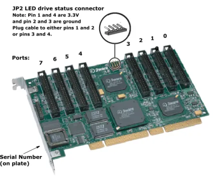
Figure 5. 8-Port Escalade 750x-8 ATA RAID Controller Layout
Note: The LED drive status connector, if used, will flash for any I/ O activity on any port.
Connect the interface cables to the Escalade ATA
RAID Controller
1 Connect the interface cables supplied with the product to the ATA RAID Controller. See Figure 5.
Serial Number (on plate) 0 2 4 6
JP2 LED drive status connector Note: Pin 1 and 4 are 3.3V and pin 2 and 3 are ground Plug cable to either pins 1 and 2 or pins 3 and 4. Ports: 7 5 0 1 3
Installing a Parallel ATA RAID Controller
Note: UltraATA-100 and UltraATA-133 drives require 40-pin, 80-conductor ribbon cables. These cables have color coded ends. For optimum performance, the blue end must be connected to the ATA RAID Controller and the black end must be connected to the hard drive.
2 One edge of each interface cable should have a colored (usually red) line denoting the conductor to Pin 1. For 8 and 12 port controllers, align the ATA RAID Controller so that the colored line is toward the top edge of the controller. For 2 and 4 port controllers, align the ATA RAID Control-ler cable so that the colored line is toward the front edge (near the bracket) of the controller card. Mate the connectors carefully without bending any pins.
3 Install the other connectors in the same manner.
Install the Escalade ATA RAID Controller in the
computer
1 If the computer is running, shut it down. Turn off power to the computer and disconnect the power cord from the outlet.
2 Open the computer case according to the manufacturer’s instructions. 3 Find the PCI or PCI-X slot you want to use for the ATA RAID Controller.
Hint: Cable routing may be easier if you install the ATA RAID Controller next to an open slot.
4 Remove the metal filler bracket for the slot. Save this screw; it will be used to secure the ATA RAID Controller after you have seated it in the slot.
Hint: While the ATA RAID Controller runs properly in any PCI slot, not all slots give equal performance due to the archi-tecture of the PCI bus. In our laboratories, we have noticed that the slots closest to the Accelerated Graphics Port (AGP) or in the 64-bit PCI slot typically give the best performance. Our card should fit in both 32-bit and 64-bit PCI slots with 5V as well as with 3.3V.
5 Line the ATA RAID Controller up so that all pins make proper contact with the PCI slot pins when pushed into place. The black end rail opposite the metal bracket may be removed if needed to fit the ATA RAID
Con-3ware Hardware Installation
troller inside the chassis. The short 4-port or 8-port Escalade ATA RAID Controller is keyed to ensure proper installation in a full-sized PCI slot. 6 Ensure that the contacts will mate with the grooves in the slot. Press down
gently on the edge of the ATA RAID Controller directly above the slot until it is fully seated.
7 Check that the ATA RAID Controller’s metal bracket covers the hole in the case and secure the bracket with the screw that was used to secure the filler bracket in step 4.
Connect the drives to the interface cables
1 Be sure to use the supplied cables. With the higher speeds of UltraATA-133 and UltraATA-100, using quality cables is important.
2 Before connecting your drives, check your drives’ jumper setting. The range of settings provided vary by manufacturer as do the method for adjusting them. Refer to information provided with your drives for the method required to set them. To operate properly, the Escalade Parallel ATA RAID Controller requires that drives be set as Single (if available on your drive) or Master.
3 If your drives are not already installed in the computer chassis, do so now. Be sure that the drives are connected to the power supply.
4 For each drive, select the black end of an interface cable not connected to the ATA RAID Controller and plug it into the drive or drive carrier. The cable’s colored edge denotes Pin 1 and should be adjacent to the 4-pin power plug.
Note: Continue to page 26 “Check your installation and close the case”.
Installing a Serial ATA RAID Controller
Installing a Serial ATA RAID Controller
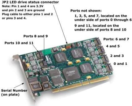
Figure 6. 12-Port Escalade 850x-12 Serial ATA RAID Controller Note: The LED drive status connector, if used, will flash for any I/O activity on any port. In most cases, for SATA this will be the only visual indication of disk drive activity, as SATA disk drives and RAID cages/carriers do not usually support LED disk drive activity indicators on a per port basis.
Note: If your serial controller is either a model 8MI or 8506-12MI, turn to page 24 and follow the instructions in that section.
Connect the interface cables to the Escalade Serial
ATA RAID Controller
1 Connect the interface cables supplied with the product to the Serial ATA RAID Controller. See Figure 6.
2 One edge of each interface cable connector is keyed to ensure proper ori-entation and installation. Carefully mate the connectors without bending any pins.
3 Install the other connectors in the same manner.
Serial Number (on plate) 0 and 1 2 and 3 4 and 5 Ports: 6 and 7 Ports 10 and 11
Ports not shown: JP2 LED drive status connector
1, 3, 5, and 7, located on the 9 and 11, located on the Note: Pin 1 and 4 are 3.3V
and pin 2 and 3 are ground Plug cable to either pins 1 and 2
or pins 3 and 4. under side of ports 0 through 6 under side of ports 8 and 10 Ports 8 and 9
3ware Hardware Installation
Note: The connectors on the end of the controller are suscepti-ble to damage from excessive bending.
4 If the computer is running, shut it down. Turn off power to the computer and disconnect the power cord from the outlet.
5 Open the computer case according to the manufacturer’s instructions. 6 Find the PCI slot you want to use for the serial ATA RAID Controller.
Hint: Cable routing may be easier if you install the ATA RAID Controller next to an open slot.
7 Remove the metal filler bracket for the slot. Save this screw; it will be used to secure the serial ATA RAID Controller after you have seated it in the slot.
Hint: While the ATA RAID Controller runs properly in any PCI or PCI-X slot, not all slots give equal performance due to the architecture of the PCI bus. In our laboratories, we have noticed that the slots closest to the Accelerated Graphics Port (AGP) or in the 64-bit PCI slot typically give the best perfor-mance. Our card should fit in both 32-bit and 64-bit PCI slots with 5V as well as with 3.3V.
8 Line up the ATA RAID Controller so that all pins make proper contact with the PCI slot pins when pushed into place. The Escalade ATA RAID Controller is keyed to ensure proper installation into a full-sized PCI slot. 9 Ensure that the contacts will mate with the grooves in the slot. Press down
gently on the edge of the ATA RAID Controller directly above the slot until it is fully seated.
10 Check that the ATA RAID Controller’s metal bracket covers the hole in the case and secure the bracket with the screw that was used to secure the filler bracket in step 4.
Connect the drives to the interface cables
Using native serial ATA drives
Installing a Serial ATA RAID Controller
2 For each drive, select the end of an interface cable not connected to the ATA RAID Controller and plug it into the drive or drive carrier. One edge of each interface cable connector is keyedto ensure proper installation.
Using parallel ATA-133 or ATA-100 drives with a converter kit
Notes:
UltraATA-66 and UltraATA-33 drives are not supported.
3ware has not tested all available converters. To determine whether a particular converter works with your 3ware controller, check with the manufacturer of the converter.
1 Before connecting your drives, check each drive’s jumper setting. The range of settings vary by manufacturer as do the method for adjusting them. Refer to information provided with your drives for the method required to set them. To operate properly, the Escalade ATA RAID Con-troller requires that drives be set as Single (if available on your drive) or Master.
2 Connect a Power Converter Adapter to each converter.
3 When you have completed step 2 for each converter, install a Converter onto the back of each parallel ATA drive. Make sure that each converter is properly aligned and securely pushed in. The converter board’s power connector must be adjacent to the drive’s power connector.
Note: The Serial ATA Converter has sharp points. Please use caution when pushing the converter onto the back of the drive.
4 Connect the Power Adapter to the power receptacle on the drive. 5 If your drives are not already installed in the computer chassis, install
them now. Be sure that the drives are connected to the power supply. 6 Connect each power adapter to the power supply.
7 For each drive, select the end of an interface cable not connected to the ATA RAID Controller and plug it into the converter.
3ware Hardware Installation
Installing a Serial ATA RAID Controller with Multi-lane
Internal Connectors
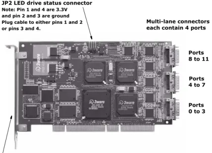
Figure 7. 12-Port Escalade 8506-12MI Serial ATA RAID Controller Models 8506-8MI and 8506-12MI have multi-lane internal connectors, each of which can handle up to four drives. These controllers can be installed in an enclosure with a backplane. The type of cable you need will depend on the type of enclosure you have:
■ For use with a backplane that has the InfiniBand 4x connectors
(SFF-8470), use the InfiniBand 4x cable, which has multi-lane connectors on each end, as shown in Figure 8.
■ For use with a backplane that has individual SATA connectors, use the
breakout cable, which has a multi-lane connector on one end, and four individual SATA connectors on the other end.
Figure 8. Multi-lane Cable (InfiniBand 4x, SFF-8470)
JP2 LED drive status connector Note: Pin 1 and 4 are 3.3V and pin 2 and 3 are ground Plug cable to either pins 1 and 2 or pins 3 and 4.
Multi-lane connectors
Serial number (on plate)
Ports 0 to 3 4 to 7 Ports 8 to 11 each contain 4 ports
Installing a Serial ATA RAID Controller with Multi-lane Internal Connectors
Install the Controller with Multi-lane Internal
Connectors in Your System
1 If the computer is running, shut it down. Turn off power to the computer and disconnect the power cord from the outlet.
2 Open the computer case according to the manufacturer’s instructions. 3 Find the PCI slot you want to use for the serial RAID controller. 4 Remove the metal filler bracket for the slot. Save this screw; it will be
used to secure the serial ATA RAID Controller after you have seated it in the slot.
Hint: While the ATA RAID Controller runs properly in any PCI slot, not all slots give equal performance due to the archi-tecture of the PCI bus. In our laboratories, we have noticed that the slots closest to the Accelerated Graphics Port (AGP) or in the 64-bit PCI slot typically give the best performance. Our card should fit in both 32-bit and 64-bit PCI slots with 5V as well as with 3.3V.
Line up the Controller so that all pins make proper contact with the PCI slot pins when pushed into place. The Escalade Con-troller is keyed to ensure proper installation into a full-sized PCI slot.
5 Ensure that the contacts will mate with the grooves in the slot. Press down gently on the edge of the ATA RAID Controller directly above the slot until it is fully seated.
6 Check that the ATA RAID Controller’s metal bracket covers the hole in the case and secure the bracket with the screw that was used to secure the filler bracket in step 4.
Connect the Interface Cables
Depending on the model of the controller and the number of drives you will be connecting, you will connect two or three multi-lane cables. Each cable supports up to four ports.
1 Connect each interface cable to a multi-lane connector on the controller. See Figure 7.
When the cable is inserted correctly, you will feel it click into place.
2 If your enclosure has a backplane, connect the other end of each interface cable to the backplane.
3ware Hardware Installation
If you are using a standard enclosure, connect each of the individual
SATA connectors to a drive.
Install the Drives
1 If your drives are not already installed, install them now, either by attach-ing them to the backplane, or by installattach-ing them in the computer chassis. 2 Be sure that the power supply is connected to either the backplane or the
individual drives.
Check your installation and close the
case
1 After all of the drives are connected to the ATA RAID Controller and it is installed in its slot, verify that the cables do not interfere with the opera-tion of any other components in the case or block the flow of cooling air. 2 Close the case and reconnect the power cables.
Check motherboard boot sequence
Using your computer’s Setup utility, ensure that your boot device precedes the Escalade ATA RAID Controller in the boot sequence. If you have other disks installed on the motherboard, the ATA RAID Controller precedes them in boot order.
3ware Disk Array
Configuration Utility
The 3ware Disk Array Configuration Utility allows you to create disk arrays by combining disks, deleting disks or breaking disk arrays back into their member disks. You can also specify an available drive as a hot spare. If an array becomes degraded, the hot spare will automatically be substituted for the faulted drive.
Note: The BIOS will not be installed if no drives are attached to the Escalade ATA RAID Controller. The ATA RAID Controller shares one IRQ on the PCI bus.
Hot spare and hot swap
Hot Spare is the label given to a drive that is available, active and designated as a spare. This designated drive is applied automatically when a drive degrades and the array is rebuilt. Hot Swap is the term applied to the process of swapping out a drive without having to shut down the system. This is use-ful when you need to swap out a defective drive, manually or automatically, with a pre-assigned spare.
There are three methods for adding a drive as a spare. You may designate a drive as a Hot Spare during the BIOS page display, you may designate a drive as a Hot Spare through the 3DM Configure page, or you may designate a drive as a Hot Spare through the CLI (Command Line Interface). The first two methods are discussed below. The CLI is available from the 3ware website at http://www.3ware.com/support/download.asp. The manual that accompanies the CLI describes how to work with it.
3ware Disk Array Configuration Utility
BIOS Screen
When designating a spare in the BIOS screen, it is assumed that as you are creating your array, you are “setting aside” drive(s) as Hot Spares. This is done by using the S key on the selected drive. Leaving a drive undesignated results in it becoming a JBOD drive. JBOD drives become available to the operating system as distinct volumes, and, consequently, they cannot be des-ignated as spares and cannot be used to rebuild degraded arrays at a later time. If a spare is designated in the BIOS screen, the designation and configuration is in effect from this point on. The spare drive will be displayed as a Hot Spare in the 3DM Configuration page.
3DM Configure Page
In order to designate an available drive as a spare from the 3DM Configure page, you select a drive that is not a JBOD drive or part of an existing array. To designate a drive as a Hot Spare from this page, you must use one of the two following methods:
Replacing a Defective Drive with a Spare
Replace the drive at the operating system level while the system is powered. This should only be done with an approved and recognized hot swap drive-carrier. If you do not use an approved and recognized hot swap drive-carrier, connecting interface cables and power cables can/will crash the system from bus or power supply issues. Select the checkbox next to the drive to be removed and click Remove Drive. Select the same checkbox and then click Add Spare.
Adding a Spare Drive to an Available Port
To add a new spare, follow the same steps except you will not be required to remove a drive.
Invoking the 3ware BIOS tool
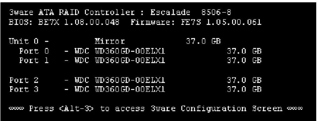
Power up or reboot your system. Before the boot phase, wait until you see a screen similar to Figure 9.
Exiting the 3ware BIOS tool
Figure 9. 3ware BIOS Tool
Press Alt-3 immediatelyto bring up the 3ware Disk Array Configuration display.
Note: If drives are attached and you do not want to install the 3ware BIOS, press Alt-b to bypass the BIOS installation. This is useful when booting temporarily from another device.
Exiting the 3ware BIOS tool
To save your configuration modifications press the F8 key. After you have pressed the F8 key to commit your changes, a list of affected drives will be displayed and you will be asked to confirm your configuration. The booting process will resume.
To exit the 3ware Disk Array Configuration Utility withoutsaving your changes press Esc.
Determining your configuration
Caution:
Configuring a disk array or hot spare writes format-type data onto its member disks and overwrites all the files on those disks. Be sure to back up data that requires retention.
■ All supported RAID levels (0,1,5,10) can be created based on the number
of drives that the ATA RAID Controller supports.
■ Multiple arrays of supported RAID levels can be implemented on a single
controller based on the number of drives that the ATA RAID Controller supports.
3ware Disk Array Configuration Utility
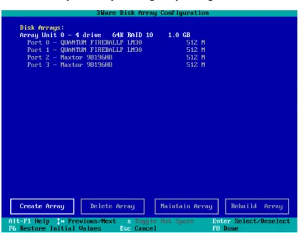
The 3ware Disk Array Configuration main display shows the current disk drive configuration.
■ Available Drives reports independent drives (JBOD) not associated with
an array and hot spares.
■ Disk Arrays lists any existing arrays along with their member disks.
Figure 10. Disk Array Configuration Main Display, RAID 1 Example Throughout the utility (see Figure 10) use the Up and Down arrow keys to navigate, Enter to select the disks or buttons and F1 for context sensitive help. Toggle Hot Spare verbiageis black when the cursor is over a drive that can be specified as a hot spare and gray when hot spare cannot be specified. If you’ve made mistakes and want to start over, pressing F6 will return your starting values. Pressing Escape will exit the configuration utility as well as abandon your changes. Pressing F8 will save your changes and exit the utility.
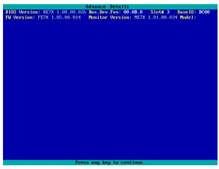
Displaying advanced details
Selecting Shift-F5 will show the software versions (BIOS, Firmware, moni-tor), slot #, and model # of the 3ware card (see Figure 11). Press Escape to return to the main 3ware Disk Array Configuration screen.
Creating a disk array
Figure 11. Disk Array Advance Details Screen
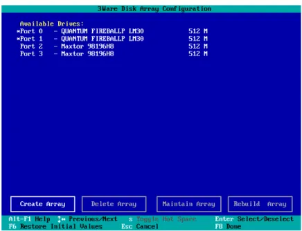
Creating a disk array
To create an array, first select the drives to be included by navigating the cur-sor over each drive and pressing Enter (see Figure 12). An asterisk in the left most column indicates the drive is selected. You may include from two to twelve drives in the array by selecting drives from the Available Drives sec-tion. To include drives that are part of an existing disk array you must first delete the array.
Note: Accelerate keys. Anywhere in the BIOS configuration screen, if a user hits the corresponding accelerate keys, it immedi-ately highlights the appropriate button:
Alt-C for “Create Array” Alt-D for “Delete Array” Alt-M for “Maintain Array” Alt-R for “Rebuild Array”
3ware Disk Array Configuration Utility
Figure 12. Selecting Drives for a Mirrored Array
Determining your configuration
Hint: The capacity of each drive is limited to the capacity of the smallest drive in the array. The total array capacity is defined as follows:
RAID 0: (the number of drives) X (the capacity of the smallest drive) RAID 1: the capacity of the smallest drive
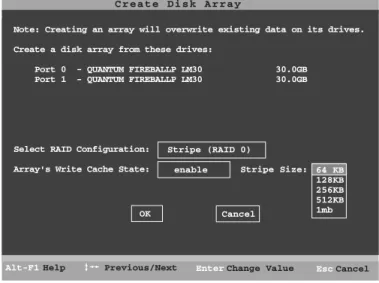
RAID 5: (the number of drives - 1) X (capacity of the smallest drive) RAID10: (the number of drives / 2) X (capacity of smallest drive) Navigate to the Create Array button after selecting all the drives for the array. Press Enter to bring up the Create Disk Array display (see Figure 13 and Figure 14 for examples). Check that the proper drives are listed.
Determining your configuration
Figure 13. Create Disk Array Display, RAID 0 Example
Figure 14. Create Disk Array Display, RAID 5 Example
Select RAID configuration
The Escalade ATA RAID Controller gives you a choice of four RAID config-urations. Select one.
■ Stripe (RAID 0): maximizes performance and capacity through a process
called striping. High performance arrays write portions of a single file across multiple drives. There is no fault tolerance.
■ Mirror (RAID 1): duplicates or “mirrors” the data on both drives. No data
will be lost if one of the drives fails. Note that a RAID 1 cannot be used to make a backup copy of an existing drive. Creating a RAID 1 erases all
C r e a t e D i s k A r r a y
Help
Alt-F1 Previous/Next Enter Change Value
Note: Creating an array will overwrite existing data on its drives. Create a disk array from these drives:
Port 0 - QUANTUM FIREBALLP LM30 30.0GB Port 1 - QUANTUM FIREBALLP LM30 30.0GB
Select RAID Configuration: Array's Write Cache State:
Stripe (RAID 0) enable Cancel OK Cancel Esc Stripe Size: 64 KB 128KB 256KB 512KB 1mb C r e a t e D i s k A r r a y Help
Alt-F1 Previous/Next Enter Change Value
Note: Creating an array will overwrite existing data on its drives. Create a disk array from these drives:
Port 1 - IBM-DTLA-387815 512 M Port 2 - IBM-DTLA-387815 512 M Port 3 - IBM-DTLA-387815 512 M
Select RAID Configuration:
Array's Write Cache State: enable
Cancel OK Cancel Esc Stripe Size: 64 KB RAID 5
3ware Disk Array Configuration Utility
■ RAID 10: combines mirroring and striping, providing both fault tolerance
and high performance. RAID 10 arrays require a minimum of four drives. Configurations consist of 4, 6, 8, 10 or 12 drives.
■ RAID 5: combines parity data and striping, providing fault tolerance, high
capacity and high storage efficiency. The parity data is distributed across all drives, rather than being concentrated on a single disk. RAID 5 arrays require a minimum of three drives. Configurations consist of at least 3 drives and up to 12 drives.
Figure 15. BIOS Initialization Screen for RAID 5
Select striping size
For a RAID 0 or RAID 10 configuration select the striping size. Sizes of 64K, 128K, 256K, 512K or 1M are selected using the Stripe Size box shown in Figure 13. RAID 5 only allows a 64K stripe size. RAID 1 does not allow the user to select the striping size.
The default stripe size of 64KB will give the best performance with applica-tions that have many sequential reads and writes. A larger stripe size will give better performance with applications that have a lot of random reads and writes. In general, the smaller the stripe size, the better the sequential I/O and the worse the random I/O. The larger the stripe size, the worse the sequential I/O and the better the random I/O.
Select write cache properties
The Escalade ATA RAID Controller gives you a choice of disabling the write cache for your disk arrays. Write cache is used to store data locally on the drive before it is written to the disk, allowing the computer to continue with
Restore Initial Values
Previous/Next Toggle Hot Spare Cancel Select/Deselect Done Alt-F1 F6 Enter F8 $ Esc Help 3 w a r e D i s k A r r a y C o n f i g u r a t i o n
Create Array Delete Array Maintain Array Rebuild Array
Available Drives:
Port 0 - QUANTUM FIREBALLP KX27.3 512 M Disk Arrays:
Array Unit 1 - 3 drive 64K RAID 5 1.0GB Port 1 - IBM-DTLA-387815 512 M Port 2 - IBM-DTLA-387815 512 M Port 3 - IBM-DTLA-387815 512 M
Init RAID5 Array Unit 1
Determining your configuration
want the computer to wait for the drive to write all the data to disk before going on to its next task. For this case, you must disable the write cache. To disable the write cache, select disable from the array’s Write Cache State selection. The default for Write Cache State is enable.
Confirm array configuration
Select the OK button to confirm creating the array or Cancel to reject it. The array is not actually created and no data will be overwritten until you have fin-ished making all your changes and select the F8 key.
Note: The current limitation is 2 TB for any physical or logical unit. If you attempt to create an array over 2 TB the BIOS will dis-play the following message:
“The amount of disk space available exceeds the maximum allow-able capacity. The array capacity will be limited to 2 TB.”
For RAID 5 Arrays
Because of the Read-Modify-Write operations, zeros are first written to all drives in the array before the array is functional. The screen shown in Figure 15 appears after selecting OK to confirm array creation.
If desired, the write-zeros operation can be aborted by rebooting the system. Once booted to the operating system, the array goes into initialization mode after a delay of up to ten minutes. The advantage of doing this is that the RAID 5 can be used immediately, although it will not be fault tolerant until the initialization is complete. The disadvantage of doing this is that it will take longer for the array to be fully redundant, as it takes longer to initialize an array than it takes to write zeros to the array.
Caution:
When running in initializing mode the array is not redundant. You cannot remove any drive.
For RAID 1 or 10Arrays
RAID 1 and 10 arrays are not profiled when created, or initialized after boot-ing into the OS. When the firmware receives the first verify request, given that the array was never initialized, the initialization will then begin. Any sub-sequent verify operations will then perform the verification of the array (check data consistency). An AEN will inform the user that the first verify will be preceded by an initialization.
3ware Disk Array Configuration Utility
Specifying a Hot Spare
The Escalade ATA RAID Controller gives you the option to specify a hot spare from one of your Available Drives. If a valid hot spare (that is, a spare that is the same size or lager than members of the redundant array) is specified and the array degrades, an event notification will be generated. The hot spare will dynamically replace the failed drive in an array without user intervention. Select a hot spare by navigating to an Available Drive. The Toggle Hot Spare verbiage at the bottom of the screen will be black if the drive can be used as a hot spare. Enter s to select the hot spare or to disable the hot spare if it is already enabled.
Note: Hot spare drives need to have the same or larger storage capacity than the RAID 1, RAID 5 or RAID 10 drives.
Changing an existing configuration
1 Back up any disk arrays that contain data that you want to retain before the configuration change.
2 Create new disk arrays following the instructions in the Determining your configuration, Creating a disk array and Deleting a disk array sections. You may need to delete existing arrays to free up disks first. 3 Boot, partition and format any new disk arrays or free disks.
4 When you are finished configuring, restore from backup any data saved from previous disk arrays
Modifying a disk array
To modify an existing array you must first delete it then recreate it with the new drives. As with all disk array operations, there is no way to modify an existing array without overwriting data on the drives involved.
The 7000/8000 series Escalades do not support the feature of OCE (Online Capacity Expansion).
Deleting a disk array
To delete an array (see Figure 16) first select the array by navigating to it and hitting Enter. An asterisk in the left most column indicates the array is
How to maintain or verify a disk array
Figure 16. Delete Disk Array Display
Navigate to the Delete Array button and press Enter to bring up the Delete Disk Array display. Check that the correct drives are listed.
Select the OK key to confirm deleting the array or Cancel to reject it. Recall that the array is not actually deleted and no data will be overwritten until you have finished making all your changes and selected the F8 key.
How to maintain or verify a disk array
The Maintain Disk Array (see Figure 17) shows the current disk array con-figuration that you have selected. The array’s Write Cache State can be changed. Refer to Select write cache properties paragraph in the Creating a disk array section. Verify Array can be specified as no or yes. The default is no. Yes launches a foreground process that checks the data integrity of a fault tolerant array. If the verify array process determines that the mirrored drives are not identical or the parity is not correct, initialization of the array is launched.
Restore Initial Values
Previous/Next Toggle Hot Spare
Cancel Select/Deselect Done Alt-F1 F6 Enter F8 $ Esc Help 3 w a r e D i s k A r r a y C o n f i g u r a t i o n
Create Array Delete Array Maintain Array Rebuild Array
Available Drives: Disk Arrays:
*Array Unit 0 - 4 drive 64K RAID 0 120.0GB Port 0 - QUANTUM FIREBALLP LM30 30.0GB Port 1 - QUANTUM FIREBALLP LM30 30.0GB Port 2 - QUANTUM FIREBALLP LM30 30.0GB Port 3 - QUANTUM FIREBALLP LM30 30.0GB
3ware Disk Array Configuration Utility
Figure 17. Maintain Disk Array Display
Note: Fault tolerant arrays can not be verified until after they are initialized. For RAID 1 and 10 arrays the initial verify can be done in the BIOS, in 3DM, or through the CLI.
Rebuilding a mirrored disk array
Escalade ATA RAID Controllers allow you to create fault tolerant disk arrays by selecting a mirrored RAID 1 or RAID 10 array. These disk arrays store identical data on two or more drives to protect against drive failure. If one or more of the drives of a mirrored array is removed, unplugged or fails on read or write requests, the array is marked as DEGRADED and the drive is marked as Not In Use or is not displayed if no longer available. (see Figure 18 and Figure 19).
You can still read and write data from a degraded disk array, but the array will not be fault tolerant until it is rebuilt using the Rebuild feature, described in the 3ware Disk Array Configuration Utility or 3DM Disk Management Utility
chapters, or until it is automatically rebuilt using a previously created hot spare. M a i n t a i n D i s k A r r a y enabled no Cancel OK
The array listed below can have its write cache state changed. Verify checks the data integrity of a fault tolerant array. Array Unit 2 - 2 drive Mirror 30.0GB
Port 2 - QUANTUM FIREBALLP LM30 30.0GB Port 3 - QUANTUM FIREBALLP LM30 30.0GB
Array's Write Cache State: Verify Array:
Help
Rebuilding a mirrored disk array
Figure 18. Degraded RAID 1 Array Drive When Not in Use
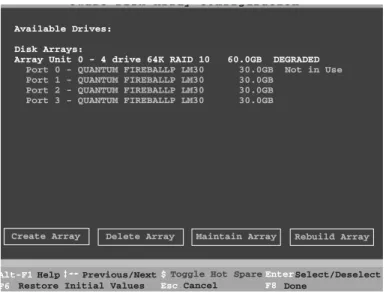
Figure 19. Degraded RAID 10 Array Drive When Not in Use
Note: A RAID 10 array can be configured with either four, six, eight, ten or twelve drives. In a 4-drive configuration, up to two drives can be rebuilt. In a 6-drive configuration, up to three drives can be rebuilt. In an 8-drive configuration, up to four drives can be rebuilt. In a 12-drive configuration, up to six drives can be rebuilt. Restore Initial Values
Previous/Next Toggle Hot Spare
Cancel Select/Deselect Done Alt-F1 F6 Enter F8 $ Esc Help 3 w a r e D i s k A r r a y C o n f i g u r a t i o n
Create Array Delete Array Maintain Array Rebuild Array Available Drives:
Port 2 - QUANTUM FIREBALLP LM30 30.0GB Port 3 - QUANTUM FIREBALLP LM30 30.0GB Disk Arrays:
Array Unit 0 - 2 drive Mirror 30.0GB DEGRADED Port 0 - QUANTUM FIREBALLP LM30 30.0GB Not in Use Port 1 - QUANTUM FIREBALLP LM30 30.0GB
3 w a r e D i s k A r r a y C o n f i g u r a t i o n
Create Array
Restore Initial Values
Previous/Next Toggle Hot Spare Cancel Select/Deselect Done Alt-F1 F6 Enter F8 $ Esc
Delete Array Maintain Array Rebuild Array Available Drives:
Disk Arrays:
Array Unit 0 - 4 drive 64K RAID 10 60.0GB DEGRADED Port 0 - QUANTUM FIREBALLP LM30 30.0GB Not in Use Port 1 - QUANTUM FIREBALLP LM30 30.0GB
Port 2 - QUANTUM FIREBALLP LM30 30.0GB Port 3 - QUANTUM FIREBALLP LM30 30.0GB