MasterCAL
Calibrator
Users Manual
June 2004© 2004 Beta. All rights reserved.
All product names are trademarks of their respective companies. Beta Calibrators Corporation is a unit of Martel Electronics For more information on Martel go to www.martelcorp.com
Martel Electronics Corporation warrants all products against material defects and workmanship for a period of twelve (12) months after the date of shipment. Problems or defects that arise from misuse or abuse of the instrument are not covered. If any product is to be returned, a “Return Material Authorization” number must be obtained from our Customer Service Department. This number must be indicated on the return package as notice to our Receiving Department to accept the shipment. Any package not so marked will not be accepted and will be returned to the shipper. Martel will not be responsible for damage as a result of poor return packaging. Out of warranty repairs and recali-bration will be subject to specific charges. Under no circumstances will Martel Electronics be liable for any device or circumstance beyond the value of the product.
Customer Service
For service please contact Beta: Beta Calibrators Corporation
A unit of Martel Electronics 2309 Springlake Road, #600 Farmers Branch, TX 75234-5875 1-800-537-2181
972-241-2200
Or visit us on the World Wide Web: www.betacalibrators.com
Table of Contents
Title Page
Introduction... 1
Standard Equipment... 2
Safety Information ... 7
Getting Started Exercise... 10
Operating Features... 12
Input and Output Jacks... 12
Keys... 14
Display ... 17
Setting Up the Calibrator ... 19
Using the Strap and Bail ... 19
Charging the Battery... 20
Battery Life... 22
Preserving Battery Life ... 23
Using the Optional Battery Eliminator ... 23
Adjusting the Display Contrast ... 24
Displaying the Date and Time ... 24
Using the Backlight ... 26
Personalizing the Calibrator ... 26
Using Measure Mode ... 28
Measurement Ranges ... 28
Measuring Electrical Parameters ... 28
Testing Continuity ... 30
Measuring Pressure ... 30
Measuring Temperature ... 34
Using Thermocouples... 34
Using Resistance-Temperature Detectors (RTDs) ... 37
Measurement Scale ... 41
Linear-Output Transmitters... 41
Square-Law Process Variables ... 42
Measuring or Sourcing with Custom Units ... 43
Using the 700-IV Current Shunt ... 44
Damping Your Measurements... 44
Using Source Mode... 46
Sourcing Electrical Parameters ... 46
Simulating a 4 to 20 mA Transmitter ... 48
Supplying Loop Power ... 50
Sourcing Pressure... 52
Simulating Thermocouples... 55
Simulating RTDs ... 56
Source Scale ... 62
Linear-Responding Transmitters ... 62
Contents (continued)
Stepping and Ramping the Output Value ... 63
Using Manual Step... 63
Using Auto Step ... 64
Ramping the Output ... 65
Simultaneous Measure/Source ... 68
Calibrating a Process Instrument ... 71
Generating “As Found” Test Data... 71
Adjusting the Transmitter... 76
“As Left” Test Run... 77
Test Comments ... 78
Calibrating a Delta-Pressure Flow Instrument ... 78
Calibrating a Limit Switch ... 79
Transmitter Mode ... 82
Memory Operations ... 84
Saving Results... 84
Reviewing Memory ... 86
Data Logging ... 86
Recording Min and Max Measurements ... 89
Running a Preloaded Task ... 89
Clearing Memory ... 89
Using the Built-in Calculator ... 90
Saving to and Recalling from the Registers... 90
Using the Calculator to Set the Source Value ... 91
Quick Guide to Applications ... 91
Replacing the Battery Pack ... 101
Internal Lithium Backup Battery... 102
Cleaning the Calibrator ... 102
In Case of Difficulty ... 102
Service Center Calibration or Repair... 103
Replacement Parts... 104 Accessories... 105 Specifications... 106 DC Voltage Measurement ... 107 AC Voltage Measurement ... 108 DC Current Measurement ... 109 Resistance Measurement... 109 Continuity Testing ... 110 Frequency Measurement ... 110 DC Voltage Output ... 111 DC Current Output ... 112 Resistance Sourcing ... 113 Frequency Sourcing ... 114 Temperature, Thermocouples ... 115
Temperature, Resistance Temperature Detectors ... 118
Loop Power Supply ... 120
Top and Bottom Limits of Ranges with Auto Range On ... 121
General Specifications ... 123 Index
List of Tables
Table Title Page
1. Summary of Source and Measure Functions ... 4
2. Input/Output Jacks and Connectors ... 12
3. Key Functions ... 15
4. Battery Life ... 22
5. Thermocouple Types Accepted ... 35
6. RTD Types Accepted... 37
7. Simultaneous MEASURE/SOURCE Functions with Loop Power Disabled ... 69
8. Simultaneous MEASURE/SOURCE Functions with Loop Power Enabled... 70
List of Figures
Figure Title Page
1. Standard Equipment ... 5
2. Definition of Symbols ... 7
3. Jumper Connections for Demonstration ... 11
4. Measure/Source Example ... 11
5. Input/Output Jacks and Connectors ... 13
6. Keys... 14
7. Elements of a Typical Display ... 18
8. Using the Bail and Installing the Strap... 19
9. Removing the Battery and Using the Charger ... 21
10. Electrical Measurement Connections ... 29
11. Connections for Measuring Pressure ... 33
12. Measuring Temperature with a Thermocouple ... 36
13. Using a Jumper Correctly ... 39
14. Measuring Temperature with an RTD... 40
15. Electrical Sourcing Connections ... 47
16. Connections for Simulating a 4 to 20 mA Transmitter ... 49
18. Connections for Sourcing Pressure ... 54
19. Connections for Simulating a Thermocouple ... 57
20. Connections for Simulating an RTD ... 58
21. Sourcing Temperature using Drywell ... 60
22. Checking a Relay Output Trip Alarm... 67
23. Calibrating a Thermocouple Temperature Transmitter ... 73
24. Limit Switch Terminology ... 79
25. Calibrating a Chart Recorder ... 92
26. Measuring Voltage Drop ... 92
27. Monitoring AC Line Voltage and Frequency ... 93
28. Calibrating a Current-to-Pressure (I/P) Transmitter ... 94
29. Measuring the Output Current of a Transmitter... 95
30. Measuring a Precision Resistor ... 96
31. Sourcing Resistance ... 96
32. Checking a Switch... 97
33. Checking a Tachometer ... 97
34. Calibrating a Pressure-to-Current (P/I) Transmitter ... 98
35. Calibrating a mV to Current Transmitter... 99
36. Checking a Vortex Sheeding Flowmeter ... 100
Calibrator
Introduction
The Beta MasterCAL Calibrator (hereafter referred to as the calibrator) is a battery-powered, hand-held instrument that measures and sources electrical and
physical parameters, and provides basic HART
communicator functions when used with
HART-capable transmitters. Refer to the MasterCAL
HART Mode Users Guide for instructions on how to use the HART communication feature.
The calibrator lets you troubleshoot, calibrate, verify, and document your work on process instruments. Calibrator Specifications are at the back of the manual.
A summary of the measuring and sourcing functions provided by the calibrator is shown in Table 1. In
addition to these functions, the calibrator has the following features:
• General features:
An analog display to make it easy to read measurements when the input is unstable. A setup option that lets you set the display to English, French, German, Italian, or Spanish. A thermocouple (TC) input/output jack and internal isothermal block with automatic reference-junction temperature compensation. Or, you can manually enter an external temperature reference.
The ability to automatically log up to 8,000 data points.
A serial computer interface for
uploading/downloading tasks, lists, and results. Automatic calibration procedures for
transmitters and limit switches using split screen MEASURE/SOURCE mode.
Transmitter mode in which the calibrator can be configured to emulate the functions of a process instrument.
Built-in calculator with square-root function, and accessible registers containing measure and source values.
An optional bar code wand for entering alphanumeric characters.
• Measuring features:
Damping (smoothing of the last several readings), with display indicator of damped status.
Display of measurements in engineering units, percent of scale, square-law inputs, or custom units.
The ability to capture and display minimum and maximum measured levels.
• Sourcing features:
The ability to set source values to engineering units, percent of scale, square-law outputs, or custom units.
Manual and automatic stepping, and an output ramp feature for testing limit switches. Trip detect is either a 1 V change or a continuity status change (Open or Short) from one ramp increment to the next.
For performance testing and calibration instructions contact Beta.
To contact Beta, call: USA and Canada: 1-800-537-2181 972-241-2200
Or visit us on the World Wide Web: www.betacalibrators.com
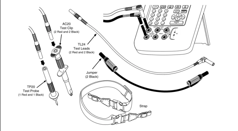
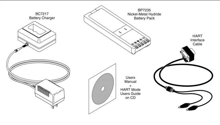
Standard Equipment
The items listed below and shown in Figure 1 are included with your calibrator. If the calibrator is
Standard Equipment
damaged or something is missing, contact the place of purchase immediately. To order replacement parts or spares, see the user-replaceable parts list at the end of this manual.
• TL24 industrial test leads (two sets)
• AC20 test clips (two sets)
• TP20 test probes (one set)
• HART interface cable
• BP7235 rechargeable nickel-metal hydride pack
• BC7217 battery charger with Instruction Sheet
• Adjustable quick-release strap (PN 946769)
• Jumper for three-wire RTD measurement
connections (two included, PN 944632)
• MasterCAL Users Manual on CD
Table 1. Summary of Source and Measure Functions
Function Measure Source
vdc V 0 V to +/-300 V 0 V to 15 V (10 mA max)
hac V 0 V to 300 V rms, 20 Hz to 5 kHz No sourcing
hFrequency 1 Hz to 1 kHz (100 mV to 300 V rms) 1 kHz to 30 kHz (0.5 V to 30 V rms) 30 kHz to 50 kHz (1 V to 30 V rms)
0.1 V to 10 V p-p sine wave, or peak square wave, 0 Hz to 50 kHz
qResistance 0 Ω to 11 k Ω 0 Ω to 11 k Ω
mdc Current 0 mA to 110 mA 0 to 22 mA (28 V max), sourcing or sinking
qContinuity Beep and the word Short indicates continuity No sourcing
tThermocouple Types E, N, J, K, T, B, R, S, C, L, or U tRTD 100 Ω Platinum (3926) 100 Ω Platinum (385) 120 Ω Nickel (672) 200 Ω Platinum (385) 500 Ω Platinum (385) 1000 Ω Platinum (385) 10 Ω Copper (427) 100 Ω Platinum (3916)
pPressure 27 modules ranging from 0 to 10 in. H2O
(2.5 kPa) to 0 to 10,000 psi (69,000 kPa)
Note
sLoop Power 24 or 28 V (22 mA max)
Standard Equipment
Jumper (2 Black) AC20
Test Clip (2 Red and 2 Black)
TP20 Test Probe (1 Red and 1 Black)
7 8 9 4 5 6 1 2 3 0 . V V Hz TC RTD CLEAR ( ZERO) ENTER V RTD MEAS SOURCE mA mA RTD V 300V MAX 30V MAX TC TL24 Test Leads (2 Red and 2 Black)
Strap
ot01f.eps
BP7235 Nickel-Metal Hydride Battery Pack HART Interface Cable Users Manual + HART Mode Users Guide on CD BC7217 Battery Charger ot02f.eps
Safety Information
Safety Information
This calibrator is designed and tested in accordance with IEC1010-1 and CAN/CSA C22.2 No.
1010.1-92. Use the calibrator only as specified in
this manual, otherwise the protection provided by the calibrator may be impaired.
Symbols used on the calibrator and in this manual are explained in Figure 2.
AC-Alternating Current
DC-Direct Current
CAUTION see explanation in manual
Overvoltage (Installation) Category II, Pollution Degree 2 per IEC 1010-1 refers to the level of Impluse Withstand Voltage protection provided. Typical locations include; Mains Wall outlets, local appliances and PORTABLE EQUIPMENT.
Fuse
Common (LO) Input equipotentiality
Recycling Pressure
ON/OFF
Equipment protected throughout by DOUBLE INSULATION or REINFORCED INSULATION
Conforms to relevent European Union directives.
Conforms to relevent Canadian Standards Association directives.
CAT II
gj56f.eps
Safety Information (cont)
A Warning identifies conditions and actions that pose hazards to the user; a Caution identifies conditions and actions that may damage the calibrator or the equipment under test.
W
Warning
To avoid electric shock or personal injury, adhere to the following practices:
• Do not use the calibrator if it is damaged. Before you use the calibrator, inspect the insulating cover. Look for cracks or missing plastic. Pay particular attention to the insulation surrounding the connectors.
• Disconnect the power and discharge all high-voltage capacitors in the equipment under test before testing resistance or continuity.
• Inspect the test leads for damaged insulation or exposed metal. Check test lead continuity. Replace damaged test leads before using the calibrator.
• Do not use the calibrator if it operates abnormally. Protection may be impaired. When in doubt, have the calibrator serviced.
• Select the proper function and range for your measurement.
• Use caution when working above 30 V ac rms, 42 V ac pk, or 60 V dc. Such voltages pose a shock hazard.
• When using the probes, keep your fingers away from the probe contacts. Keep your fingers behind the finger guards on the probes.
• Connect the common test lead before you connect the live test lead. When you disconnect test leads, disconnect the live test lead first.
• Replace the battery as soon as there is a low battery indication on the display. The
possibility of false readings can lead to electric shock and personal injury.
Safety Information
Safety Information (cont)
W
Warning (cont)
• Do not apply more than the rated voltage, as marked on the calibrator, between the terminals, or between any terminal and earth ground.
• When using probes, keep your fingers behind the finger guards.
• Do not use the calibrator with any part of the case or cover removed.
• Do not operate the calibrator around explosive gas, vapor, or dust.
• When using a pressure module, make sure the process pressure line is shut off and depressurized before you connect it to or disconnect it from the pressure module.
• Disconnect test leads before changing to another measure or source function.
• When servicing the calibrator, use only specified replacement parts.
• Do not use any battery eliminator other than the Fluke model BE9005 Battery Eliminator.
Caution
To avoid possible damage to the calibrator or the equipment under test, follow these guidelines:
• Disconnect circuit power and discharge all high-voltage capacitors before testing resistance, continuity, diodes, or capacitance.
• Use the proper terminals, function, and range for your measurements.
Getting Started Exercise
The following is a brief getting started exercise that will make it easier to understand the instructions in the rest of the manual.
1. When you first unpack the calibrator, you will
need to charge the battery. See Figure 9 and charge the battery for 2 hours.
2. Reinstall the battery in the calibrator.
3. Connect the calibrator’s voltage output to its
voltage input as follows: connect leftmost pair of
jacks (V Ω RTD SOURCE) to the right most pair
of jacks (V MEAS). (See Figure 3.)
4. Press o to turn on the calibrator. Press u and
d to adjust the display contrast for the best
looking display. The calibrator powers up in the dc voltage measurement function, and is taking readings on the V MEAS pair of input jacks.
5. Press s to switch to the SOURCE screen.
The calibrator is still measuring dc voltage, and you can see the active measurements at the top of the display.
6. Press v to select dc voltage sourcing.
Press 5 on the keypad and eto begin
sourcing 5.0000 V dc.
7. Now press M to go to the split-screen,
simultaneous MEASURE/SOURCE mode. The calibrator is simultaneously sourcing dc volts and measuring dc volts. You can see the measurement readings in the top window, and the active source value in the bottom window as shown in Figure 4.
Getting Started Exercise 7 8 9 4 5 6 1 2 3 0 . V V Hz RTDTC CLEAR ( ZERO) ENTER TC mA mA V RTD RTD SOURCE 30V MAX 30V MAX 30V MAX MEAS CAT V 300V MAX ot03f.eps
Figure 3. Jumper Connections for Demonstration
gj4s.eps
Operating Features
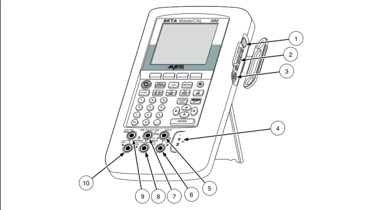
Input and Output Jacks
Figure 5 shows the calibrator input and output jacks. Table 2 explains their use.
Table 2. Input/Output Jacks and Connectors
No. Name Description
1 Battery Eliminator jack Jack for the Model BE9005 Battery Eliminator. Use the battery eliminator for bench-top applications where ac line power is available. This input does not charge the battery. 2 w SERIAL PORT Connects the calibrator to an RS-232 serial port on a personal computer.
3 Pressure module connector
Connects the calibrator to a pressure module.
4 TC input/output Jack for measuring or simulating thermocouples. This jack accepts a miniature
polarized thermocouple plug with flat, in-line blades spaced 7.9 mm (0.312 in) center to center.
5, 6 wMEAS V jacks Input jacks for measuring voltage, frequency, or three- or four-wire RTDs (Resistance Temperature Detectors).
7, 8 wSOURCE mA, MEAS mA Ω RTD jacks
Jacks for sourcing or measuring current, measuring resistance and RTDs, and supplying loop power.
9,10 wSOURCE V Ω RTD jacks
Operating Features 7 8 9 4 5 6 1 2 3 0 . V MEAS SOURCE mA SETUP V Hz RTDTC CLEAR ( ZERO) ENTER TC 10 6 4 1 2 3 7 9 8 5 mA mA V RTD RTD SOURCE 30V MAX 30V MAX 30V MAX MEAS CAT V 300V MAX BETAMasterCAL 990 ot05f.eps
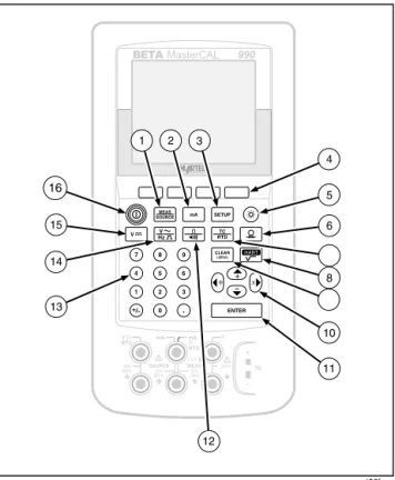
Keys
Figure 6 shows the calibrator keys and Table 3 explains their functions. The softkeys are the four unmarked blue keys just below the display. Softkey functions are defined by the labels that appear above the softkey during operation. Softkey labels and other display text are shown in this manual in bold
type, for example, Choices.
BETAMasterCAL 990 MEAS SOURCE mA SETUP V V Hz TC RTD 7 8 9 4 5 6 1 2 3 0 . ENTER CLEAR ( ZERO) 14 13 7 9 TC mA mA V V RTD RTD SOURCE 300V 30V MAX 30V MAX 30V MAX MEAS CAT 12 5 6 4 8 16 15 10 11 3 2 1 ot06f.eps Figure 6. Keys
Operating Features
Table 3. Key Functions
No. Name Description
1
M
key Cycles the calibrator through MEASURE, SOURCE, and MEASURE/SOURCE modes. 2m
key Selects mA (current) measure or source function. For loop power on/off, go to the Setupmode.
3
s
key Enters and exits Setup mode to modify operating parameters.4 Softkeys Perform the function defined by the label above each key on the display. 5
C
key Turns the backlight on and off.6
p
key Selects the pressure measurement or sourcing function.7
t
key Selects TC (thermocouple) or RTD (resistance temperature detector) measurement or sourcing functions.8
r
key Toggles between HART communication mode and analog operation. In calculator mode, this key provides the square root function.9
c
key Clears a partial data entry, or zeros the output when in the SOURCE mode. When using a pressure module, zeros the pressure module reading.Table 3. Key Functions (cont)
No. Name Description
10
u
,d
,L
, andR
keys• Adjust the display contrast.
• Make choices from lists on the display.
• Increase or decrease the source level when using the step feature.
• In calculator mode, provide arithmetic functions (+ - ÷×).
11
e
key Terminates a numeric entry when setting a source value, or confirms your choice in a list. In calculator mode, provides the equals arithmetic operator (=).12
q
key
Toggles between resistance and continuity functions in MEASURE mode, or selects the resistance function in SOURCE mode.13 Numeric keypad Used whenever a numeric entry is required.
14
h
key Toggles between ac voltage and frequency functions in MEASURE mode, or selects frequency output in SOURCE mode.15
v
key Selects the dc voltage function in MEASURE mode, or selects dc voltage in SOURCE mode.Operating Features
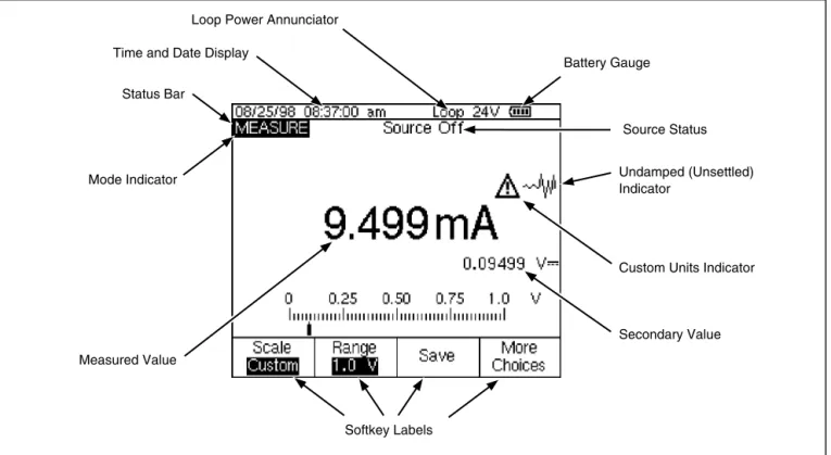
Display
Figure 7 shows the features of a typical display. The display shown is MEASURE mode. Near the top of the display is “Source Off.” This is the area of the display that shows what is happening in the other mode (SOURCE or MEASURE). The other parts of the display are as follows:
• Status Bar: shows the time and date (if set in
Setup mode), and shows the status of Loop Power, Battery Save, and Backlight Timeout; all of which are set in Setup mode. The low battery and backlight on symbols also appear here.
• Mode Indicator: Shows whether the calibrator is
in MEASURE or SOURCE mode. In split screen MEASURE/SOURCE mode, there is a Mode Indicator for each window.
• Measured Value: Shows the measured value in
your choice of engineering units or percent of scale.
• Range Status: Shows whether Auto Range is on,
and what range is currently being used.
• Custom Units Indicator: Shows that the
displayed units are custom. The original engineering units of the measure or source function are not displayed.
• Secondary Value: Shows the measure or source
value in original engineering units whenever scaling or custom units are active.
Measured Value
Softkey Labels Status Bar
Time and Date Display
Battery Gauge Loop Power Annunciator
Mode Indicator
Custom Units Indicator
Secondary Value Source Status
Undamped (Unsettled) Indicator
ot07c.eps
Setting Up the Calibrator
Setting Up the Calibrator
Using the Strap and Bail
After you unpack the calibrator, attach its carrying strap as shown in Figure 8. You can adjust the strap as necessary to hang the calibrator on any sturdy
support. Figure 8 also shows you how to open the bail to stand the calibrator at a comfortable viewing angle for benchtop use.
gj8f.eps
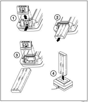
Charging the Battery
wBefore you use the calibrator for the first time,
charge its battery pack in the external battery charger. The Model BC7217 charger charges both the NiMH and Ni-Cd battery packs.
Figure 9 shows how to remove the battery. Remove the battery door and tap the calibrator with your hand to get the battery out. Place the battery in the charger and connect the charger to line power. The charger automatically senses line voltage and adjusts itself accordingly.
A discharged battery is fully charged in 2 hours or less in fast-charge mode (steady indicator light on
the charger). Full charge is maintained after that time in trickle-charge mode (blinking indicator light on the charger). Switching between charging modes is automatic. You can leave the battery pack on trickle charge indefinitely without damage.
Note
When you remove a charged battery from the charger, wait for the blinking indicator to go off before you insert a discharged battery. It takes about 2 seconds for the battery charger to reset.
Setting Up the Calibrator BATTERY ACCESS BATTERY ACCESS BATTERY ACCESS BATTERY ACCESS BATTERY ACCESS BATTERY ACCESS 1 2 3 4 gj9f.eps
Figure 9. Removing the Battery and Using the Charger
Battery Life
The calibrator senses which battery is installed (standard NiMH, or optional Ni-Cd model BP 7217). If the NiMH battery is installed, a battery gauge bar
graph Z shows on the upper right of the display.
If the Ni-Cd battery is installed, there is no battery
level indication except for a low battery symbol b,
that appears when it is time to charge the battery. Table 4 shows the typical operating time for a new, fully charged NiMH (Nickel-Metal Hydride) battery pack. The optional Ni-Cd battery (Model BP7217) provides approximately half the battery life of the
NiMH battery. Calibrator performance is guaranteed to meet specifications until the battery gauge reads
empty (Y or b).
To replace the battery, refer to “Replacing the Battery” later in this manual for instructions. In the case of the Ni-Cd battery, for longest battery life and
best performance, wait for b to appear before you
charge the battery.
Table 4. Typical Battery Life with Standard NiMH Battery Pack
Operating Modes Backlight Off Backlight On
Measure, continuous 13 Hours 12 Hours
Measure and source, with loop power on, continuous 7 Hours 6 Hours Typical intermittent operation >16 Hours >16 Hours
Setting Up the Calibrator
Preserving Battery Life
An optional Auto Battery Save feature turns the
calibrator off after a selected idle time. The default
setting for Auto Battery Save is Off. When Auto
Battery Save is On, and you are using the optional
Ni-Cd battery pack (Model BP7217), the E symbol
shows in the upper right corner of the display. The setting is preserved after you turn off the power. Auto Battery Save works the same when using the battery
eliminator. Turn on the Auto Battery Save feature as
follows:
1. Press s.
2. Press d to highlight Off following Auto Battery
Save.
3. Press e or the Choices softkey.
4. Press to u highlight On, then press e.
5. To accept the timeout period shown on the
display, you can finish here. Press Done to exit
Setup mode and do not go on to step 6.
6. To change the timeout period, press d to
highlight the timeout period following Battery
Save Timeout.
7. Press eor the Choices softkey.
8. Enter your choice of timeout period in minutes
(accepted range: 1 to 120 minutes).
9. Press the Done softkey.
10. Press the Done softkey or sto exit Setup
mode.
Using the Optional Battery Eliminator
Caution
To avoid damage to the calibrator, use only Fluke Model BE9005 Series Battery Eliminator, available from your Fluke representative.
Where ac power is available, you can use the optional Fluke Model BE9005 Battery Eliminator to conserve battery power. When the battery eliminator is used, the battery is internally disconnected, and can be removed from the calibrator. The battery eliminator does not charge the battery. The battery eliminator is handy for troubleshooting process instruments on the workbench, and for long-term data logging. When you calibrate an instrument, you will get best results using battery power.
Selecting the Display Language
The calibrator displays information in five languages. English is the default. To change the display
language, proceed as follows:
1. Press s.
2. Press the third softkey from the left twice.
3. Press d three times.
4. Press e.
5. Press uor d to highlight your choice of
language.
6. Press eto confirm your choice. The
language you choose is the power-up default.
7. Press s to exit Setup mode.
Adjusting the Display Contrast
Press u or R to increase contrast. Press d or L to
decrease contrast. When the u and d keys are
being used to select an item from a list, for example
in Setup mode, use the L or R keys. In calculator
mode, all four direction keys are used for arithmetic functions.
Displaying the Date and Time
The date and time can be shown at the top of the display during normal operation. In Setup mode you can turn this date and time display on or off. You can also control the format used to display the date and time. You should set the calendar and clock whether or not you use the date and time display, since a timestamp is applied to all saved results.
Setting Up the Calibrator
Proceed as follows to set up the time and date displays:
1. Press s.
2. Press the Next Page softkey. The display
appears as follows:
gj38s.eps
3. Use the u and d keys to move the cursor to
the parameter you want to change, then press
eor the Choices softkey to choose a
setting for that parameter. For example, the
following display appears after you select Date
Format:
gj39s.eps
4. Press uor d to move the cursor to the desired
date format.
5. Press eto go back to the sdisplay.
6. Make another selection or press the Done
softkey or s to save your settings and exit
Using the Backlight
Press C to toggle the display backlight on and off.
When the backlight is on, the G symbol shows at the
top of the display. You can minimize battery usage by setting the calibrator to turn the display backlight off automatically. When the backlight is on and Auto
Backlight Off is activated, the a symbol shows at
the top of the display. To automatically turn off the backlight after a set time, proceed as follows:
1. Press s.
2. Press d to highlight Off following Auto Backlight
Off.
3. Press eor the Choices softkey.
4. Press u to highlight On, then press e.
5. To accept the timeout period shown on the
display, press Done to exit, and do not go on to
step 6.
6. To change the timeout period, press d to
highlight the timeout period following Backlight
Timeout.
7. Press eor the Choices softkey.
8. Enter your choice of timeout period in minutes
(accepted range: 1 to 120 minutes).
9. Press the Done softkey.
10. Press the Done softkey or s to exit Setup
mode.
Personalizing the Calibrator
You can load your name or some other alphanumeric identifier into the calibrator to be displayed at power-up and in saved results. Proceed as follows to load an identifier:
1. Press s.
2. Press Next Page twice.
3. Press d to move the cursor to the same line
Setting Up the Calibrator
4. Press eor the Choices softkey. The
display appears as follows:
gj40s.eps
5. The ID string is shown at the bottom of the boxed
area. To erase a character, press the Back
Space softkey. To erase the whole string, press
c.
6. Press u, d, L, or R to select a character, then
press e. Use the numeric keypad if you
want to enter a number.
7. Repeat step 6 until you are satisfied with the ID
string appearing in the window.
8. Press the Done softkey.
9. Press the Done softkey or s to exit Setup
Using Measure Mode
NoteTo achieve best noise rejection and highest accuracy performance, do not use the battery eliminator, and tie all three common jacks together.
The operating mode (i.e., MEASURE, SOURCE) is shown in a reverse-video bar on the display. If the
calibrator is not in MEASURE mode, press M until
MEASURE is shown. You must be in MEASURE mode to change any of the MEASURE parameters.
Measurement Ranges
The calibrator normally changes to the appropriate measurement range automatically. The lower right side of the display shows either “Range” or “Auto Range” depending on the range status. Auto Range switch points are shown in the specifications at the
end of this manual. When you press the Range
softkey, the range is locked. Press it again to cycle to and lock on the next higher range. Auto Range is reactivated when you select another measurement function.
If the range is locked, overrange inputs produce a
display of - - - -. In Auto Range, out of range inputs
produce a display of ! ! ! ! ! !.
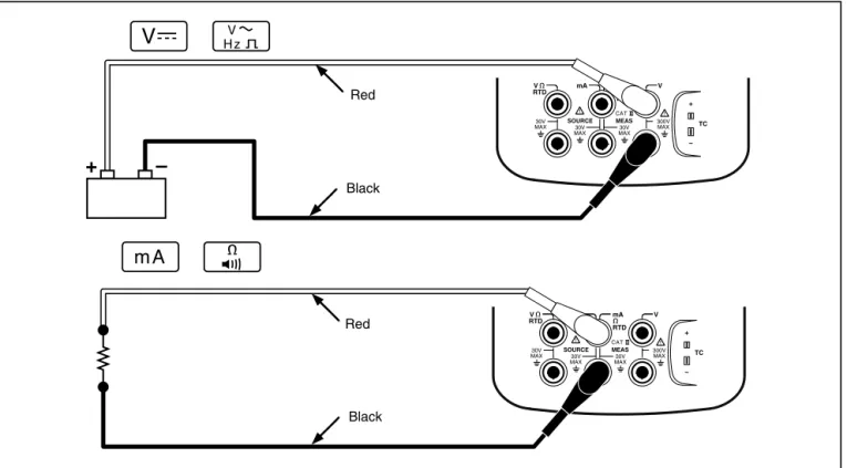
Measuring Electrical Parameters
When you turn on the calibrator, it powers up in the dc voltage measurement function. Figure 10 shows electrical measurement connections. To select an electrical measurement function from either
SOURCE or MEASURE/SOURCE mode, first press
M for MEASURE mode, then proceed as follows:
1. Press m for current, v for dc voltage, h
once for ac voltage or twice for frequency, or
Using Measure Mode TC mA mA V V RTD RTD SOURCE 300V MAX 30V MAX 30V MAX 30V MAX MEAS CAT TC mA mA V V RTD RTD SOURCE 300V MAX 30V MAX 30V MAX 30V MAX MEAS CAT Red Red Black Black
+
–
gj10f.epsNote
When measuring frequency, you are
prompted to select a frequency range. If you expect the frequency you are measuring to be below 20 Hz, press d to select the lower frequency range, then press e.
2. Connect the test leads as shown in Figure 10,
depending on the measurement function.
Testing Continuity
When testing continuity, the beeper sounds and the
word Short appears on the display when the
resistance between the Ω MEAS jack and its
common jack is less than 25 Ω. The word Open
appears when the resistance is greater than 400 Ω.
Proceed as follows to test continuity:
1. Remove power from the circuit to be tested.
2. If necessary, press M for MEASURE mode.
3. Press q twice so that Open appears.
4. Connect the calibrator to the circuit to be tested
as Figure 10 shows.
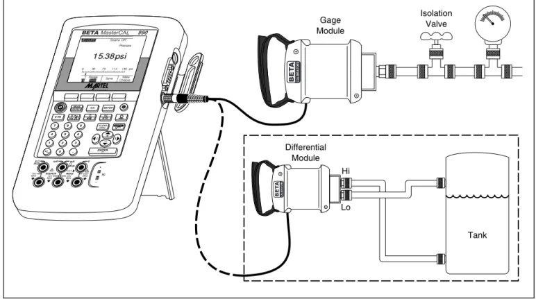
Measuring Pressure
Many ranges and types of pressure modules are available from Beta. See “Accessories” near the back of this manual. Before you use a pressure module, read its Instruction Sheet. The modules vary in how you use them, how you zero them, what types of process pressure media are allowed, and accuracy specification.
To measure pressure, attach the appropriate pressure module for the process pressure to be tested as described in the module’s Instruction Sheet.
Proceed as follows to measure pressure:
w
Warning
To avoid a violent release of pressure in a pressurized system, shut off the valve and slowly bleed off the pressure before you attach the pressure module to the pressure line.
Using Measure Mode
Caution
To avoid mechanically damaging the pressure module, never apply more than 10 ft.-lb. of torque between the pressure module fittings, or between the fittings and the body of the module. Always apply appropriate torque between the pressure module fitting and connecting fittings or adapters.
To avoid damaging the pressure module from overpressure, never apply pressure above the rated maximum printed on the pressure module.
To avoid damaging the pressure module from corrosion, use it only with specified materials. Refer to the printing on the pressure module or the pressure module instruction sheet for the acceptable material compatibility.
1. Connect a pressure module to the calibrator as shown in Figure 11. The threads on the
pressure modules accept standard ¼ NPT pipe fittings. Use the supplied ¼ NPT to ¼ ISO adapter if necessary.
2. Press M for MEASURE mode.
3. Press p. The calibrator automatically senses
which pressure module is attached and sets its range accordingly.
4. Zero the pressure module as described in the
module’s Instruction Sheet. Modules vary in zeroing procedures depending on module type. You MUST perform this step before you execute a task that sources or measures pressure.
5. If desired, you can change pressure display
units to psi, mHg, inHg, mH2O, inH2O@,
inH2O@60°F, ftH2O, bar, g/cm
2
, or Pa. Metric units (kPa, mmHg, etc.) are shown in Setup mode in their base units (Pa, mHg, etc.). Change the pressure display units as follows:
a. Press s.
b. Press Next Page twice.
c. Press eor the Choices softkey with
the cursor on Pressure Units.
d. Select the pressure units with u or d.
e. Press e.
Using Measure Mode 7 8 9 4 5 6 1 2 3 0 . V MEAS SOURCE mA SETUP V Hz TC RTD CLEAR ( ZERO) ENTER TC Isolation Valve Gage Module mA mA V V RTD RTD SOURCE 300V MAX 30V MAX 30V MAX 30V MAX MEAS CAT BETAMasterCAL 990 Differential Module Tank Hi Lo ot12c.eps
Measuring Temperature
Using Thermocouples
The calibrator supports eleven standard thermocouples, each identified with an alpha character: E, N, J, K, T, B, R, S, C, L, or U. Table 5 summarizes the ranges and characteristics of the supported thermocouples.
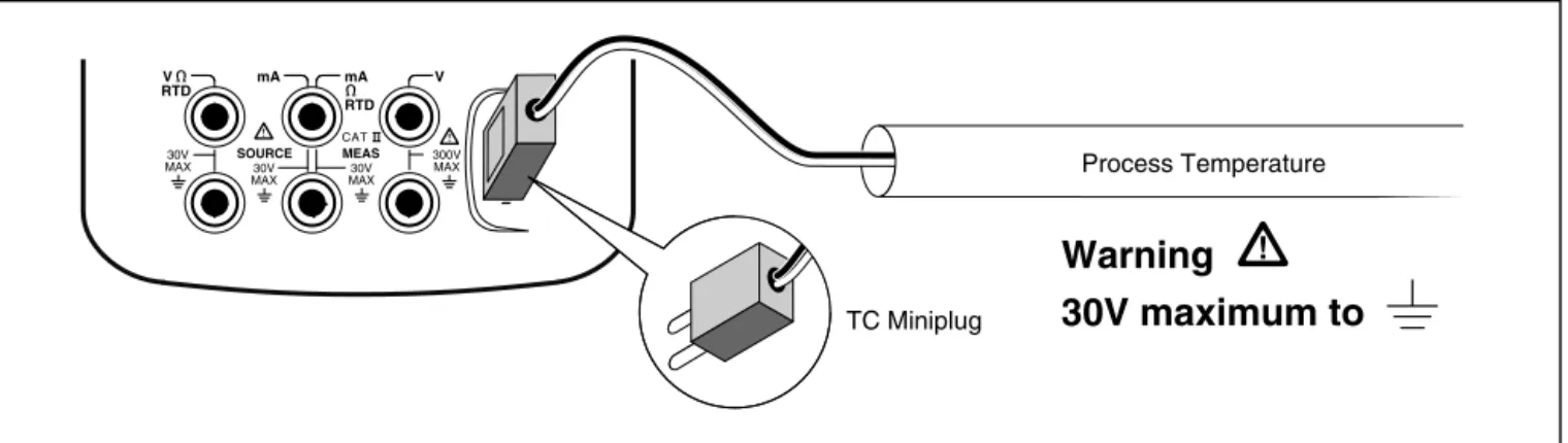
To measure temperature using a thermocouple, proceed as follows:
1. Attach the thermocouple leads to the appropriate
TC miniplug, then to the TC input/output as
shown in Figure 12. One pin is wider than the
other. Do not try to force a miniplug in the wrong polarization.
Note
If the calibrator and the thermocouple plug are at different temperatures, wait one minute or more for the connector
temperature to stabilize after you plug the miniplug into the TC input/output.
2. If necessary, press M for MEASURE mode.
3. Press t. Choose “TC”, then the display
prompts you to select the thermocouple type.
4. Select the desired thermocouple type using the
u or d followed by e.
5. If necessary, you can change between °C or °F
Temperature Units as follows:
a. Press s.
b. Press the Next Page softkey twice.
c. Use the u and d keys to move the cursor
to the desired parameter. Then press either
eor the Choices softkey to choose a
setting for that parameter.
d. Press u or d to move the cursor to the
desired setting.
e. Press eto go back to the sdisplay.
f. Press the Done softkey or sto exit Setup
mode.
6. If necessary, you can change between ITS-90 or
IPTS-68 Temperature Scale in Setup mode. The
Using Measure Mode
Table 5. Thermocouple Types Accepted
Type Positive Lead
Positive Lead (H)
Color Negative Lead Specified Range
Material ANSI* IEC** Material (°C)
E Chromel Purple Violet Constantan -250 to 1000
N Ni-Cr-Si Orange Pink Ni-Si-Mg -200 to 1300
J Iron White Black Constantan -210 to 1200
K Chromel Yellow Green Alumel -270 to 1372
T Copper Blue Brown Constantan -250 to 400
B Platinum (30% Rhodium) Gray Platinum (6% Rhodium) 600 to 1820 R Platinum (13% Rhodium) Black Orange Platinum -20 to 1767 S Platinum (10% Rhodium) Black Orange Platinum -20 to 1767 C *** Tungsten (5% Rhenium) White Tungsten (26% Rhenium) 0 to 2316
L (DIN J) Iron Constantan -200 to 900
U (DIN T) Copper Constantan -200 to 600
*American National Standards Institute (ANSI) device negative lead (L) is always red. **International Electrotechnical Commission (IEC) device negative lead (L) is always white. *** Not an ANSI designation but a Hoskins Engineering Company designation.
TC mA mA V V RTD RTD SOURCE 300V MAX 30V MAX 30V MAX 30V MAX MEAS CAT Process Temperature
Warning
30V maximum to
TC Miniplug gj12f.epsUsing Measure Mode
Using Resistance-Temperature Detectors
(RTDs)
The calibrator accepts RTD types shown in Table 6. RTDs are characterized by their resistance at 0 °C
(32 °F), which is called the “ice point” or R0. The
most common R0 is 100 Ω. Most RTDs come in a
three-terminal configuration. The calibrator accepts RTD measurement inputs in two-, three-, or four-wire connections as shown in Figure 14. A four-wire configuration provides the highest measurement precision, and two-wire provides the lowest measurement precision.
Table 6. RTD Types Accepted
RTD Type Ice Point (R0) Material α Range (°C)
Pt100 (3926) 100 Ω Platinum 0.003926 Ω/°C -200 to 630 *Pt100 (385) 100 Ω Platinum 0.00385 Ω/°C -200 to 800 Ni120 (672) 120 Ω Nickel 0.00672 Ω/°C -80 to 260 Pt200 (385) 200 Ω Platinum 0.00385 Ω/°C -200 to 630 Pt500 (385) 500 Ω Platinum 0.00385 Ω/°C -200 to 630 Pt1000 (385) 1000 Ω Platinum 0.00385 Ω/°C -200 to 630 Cu10 (427) 9.035 Ω ** Copper 0.00427 Ω/°C -100 to 260 Pt100 (3916) 100 Ω Platinum 0.003916 Ω/°C -200 to 630 *Per IEC 751-Standard **10 Ω @ 25 °C
To measure temperature using an RTD input, proceed as follows:
1. If necessary, press M for MEASURE mode.
2. Press t. Choose “RTD”, then the display
prompts you to Select RTD Type.
3. Press u or d to select the desired RTD type.
4. Press e.
5. Press u or d to select a 2-, 3-, or 4- wire
connection.
6. Attach the RTD to input jacks as the display or
Figure 15 shows. Use the supplied jumper
between the mA Ω RTD MEAS low jack and the
V MEAS low jack as shown if you are using a 3-wire connection.
7. Press e.
Caution
Do not force a dual banana plug between any two jacks in the horizontal
orientation. Doing so will damage the jacks. Use the supplied jumper wire when needed for RTD measurements. You can use a dual banana plug in the vertical orientation. See Figure 13.
Using Measure Mode TC mA mA V RTD RTD SOURCE 30V MAX 30V MAX 30V MAX MEAS CAT V 300V MAX OK V RTD MEAS SOURCE mA mA RTD V 300V MAX 30V MAX TC V RTD MEAS SOURCE mA mA RTD V 300V MAX 30V MAX TC WRONG gj14f.eps
Figure 13. Using a Jumper Correctly
8. If necessary, you can change between °C or °F
temperature units in Setup mode as follows:
a. Press s.
b. Press the Next Page softkey twice.
c. Use the u and d keys to move the cursor
to the parameter you which to change, then
press e or the Choices softkey to
choose a setting for that parameter.
d. Press u or d to move the cursor to the
desired setting.
e. Press eto go back to the sdisplay.
f. Press the Done softkey or s to exit Setup
mode.
9. If necessary, you can change between ITS-90 or
IPTS-68 Temperature Scale in Setup mode. The
procedure is the same as steps a through f above.
TC mA mA V V RTD RTD SOURCE 300V MAX 30V MAX 30V MAX 30V MAX MEAS CAT TC mA mA V V RTD RTD SOURCE 300V MAX 30V MAX 30V MAX 30V MAX MEAS CAT TC mA mA V V RTD RTD SOURCE 300V MAX 30V MAX 30V MAX 30V MAX MEAS CAT RTD RTD RTD gj15f.eps
Using Measure Mode
Measurement Scale
This feature lets you scale the measurements in accordance with a particular process instrument’s response. Percent of scale works for linear-output transmitters or square-law transmitters such as differential pressure transmitters that report flow rate.
Linear-Output Transmitters
1. If necessary, press M for MEASURE mode.
2. Select a measurement function (m,v,
h,q, t, or p) as previously described.
3. Press the Scale softkey.
4. Select % scale from the list.
5. Use the numeric keypad to enter the 0% of scale
value (0% Value).
6. Press e.
7. Use the numeric keypad to enter the 100% of
scale value (100% Value).
8. Press e.
9. Press the Done softkey.
Percent of scale remains in effect until you change to
another measurement function or press the Scale
Square-Law Process Variables
When you select √ within scaling, the calibrator takes
the square root of its input and displays the measurement in percent. For example, when connected to the output of a delta-pressure transmitter, the calibrator reading is proportional to flow rate.
1. If necessary, press M for MEASURE mode.
2. Select a measurement function (m,v,
h,q, t, or p) as previously
described.
3. Press the Scale softkey.
4. Select √ scale from the list.
5. Use the numeric keypad to enter the 0% of scale
value (0% Value).
6. Press e.
7. Use the numeric keypad to enter the 100% of
scale value (100% Value).
8. Press e.
9. Set Mode to √.
10. Press e.
11. Press the Done softkey.
Square root percent of scale remains in effect until you change to another measurement function or
press the Scale softkey and select another scale
Using Measure Mode
Measuring or Sourcing with Custom
Units
w
Warning
To avoid possible electric shock, when using Custom Units for measurement, always refer to the secondary value displayed below and to the right of the main display for the actual value of the measurement in native engineering units.
You can set up the measurement or source display to show your own custom units. To do this, you select a function, for example mV dc, scale it as you choose, then enter an alphanumeric name for your custom units, for example, “PH.”
Proceed as follows to set up a custom unit:
1. When measuring or sourcing the function of your
choice, press the Scale softkey, then select
Custom Units from the list.
2. Enter the 0% and 100% scale points for the input
of your transfer function.
3. Press the Custom Units softkey.
4. Enter the 0% and 100% scale points for the
output of your transfer function.
5. Enter the name of the custom units (up to four
characters), for example PH (for pH), using the
alphanumeric entry window, then press e.
While Custom Units are active, the wsymbol shows
on the display to the right of the custom unit. Once you have programmed the custom measurement unit, the custom unit is available for calibration procedures in split-screen MEASURE/SOURCE
mode. To cancel Custom Units, press the
Using the 700-IV Current Shunt
To source and measure current simultaneously, you need to use a current shunt and use the volts measure function. The Fluke 700-IV current shunt is designed specifically for use with the MasterCAL Calibrators. To measure current with the current shunt, proceed as follows:
1. Connect the current shunt to the MEAS V jacks
(rightmost).
2. Connect the current signal to be measured to the
current shunt.
3. Select the dc voltage measure function.
4. Press the Scale softkey.
5. Select Current Shunt from the list.
6. The calibrator is automatically configured using
custom units appropriate for the current shunt.
Damping Your Measurements
The calibrator normally applies a software filter to dampen measurements in all functions except continuity. The specifications assume that damping is turned on. The damping method is a running average of the last several measurements. Beta recommends that you leave damping on. Turning damping off may be useful when measurement response is more important than accuracy or noise reduction. If you want to turn off damping, press the
More Choices softkey twice, then press the Dampen
softkey so that Off appears. Press Dampen again to
Using Measure Mode
Note
If a measurement falls outside a random noise window, a new average is started. If damping is turned off, or until measurements are fully damped, the g symbol is displayed.
Using Source Mode
The operating mode (i.e., MEASURE, SOURCE) is shown in a reverse-video bar on the display. If the
calibrator is not in SOURCE mode, press M until
SOURCE is shown. You must be in SOURCE mode to change any of the SOURCE parameters.
Sourcing Electrical Parameters
To select an electrical sourcing function, proceed as follows:
1. Connect the test leads as shown in Figure 16,
depending on the source function.
2. Press m for current, v for dc voltage, h
for frequency, or q for resistance.
3. Enter the desired output value, then press
e. For example, to source 5.0 V dc, press
v5.0e.
Note
If you are sourcing frequency, respond to the display prompt to select a zero-symmetric sine or positive square wave. The amplitude you specify is p-p amplitude.
4. To change the output value enter a new value
and press e.
Note
If you are sourcing current, wait for theg
symbol to go out before you use the output.
5. To set the output value to 0 in the present
source function, press c.
6. To turn off sourcing completely, press c
twice.
Note
Use the source current function to drive a current loop. This is different than the loop power function in which the calibrator is powering a process instrument. To source loop power, use the Loop Power function accessible from Setup mode.
Using Source Mode TC mA mA V V RTD RTD SOURCE 300V MAX 30V MAX 30V MAX 30V MAX MEAS CAT TC mA mA V V RTD RTD SOURCE 300V MAX 30V MAX 30V MAX 30V MAX MEAS CAT Red Black
+
–
+
–
Red Black Common Common gj16f.epsSimulating a 4 to 20 mA Transmitter
You can configure the calibrator as a load on a current loop through the SOURCE mA function.
When you press the M key in SOURCE mode, the
display prompts you to select Source mA or Simulate
Transmitter. When you Source mA the calibrator is
sourcing current, and when you Simulate Transmitter
the calibrator is sourcing a variable resistance to regulate current to the specified value. Connect an external loop supply to the positive (top) mA jack as shown in Figure 16.
Note
Also see “Transmitter Mode,” in which the calibrator can be set up to temporarily take the place of a two-wire process transmitter.
Using Source Mode BETAMasterCAL 990 TC mA mA V V RTD RTD SOURCE 300V MAX 30V MAX 30V MAX 30V MAX MEAS CAT MEAS SOURCE mA SETUP V V Hz TC RTD 7 8 9 4 5 6 1 2 3 0 . Loop Power Supply +24 UUT Black Red
+
–
ENTER CLEAR ( ZERO) ot17c.epsSupplying Loop Power
The calibrator supplies loop power at 28 V or 24 V dc
through an internal series resistance of 250 Ω. The
28 V setting supplies enough current for two or three 4-20 mA devices on the loop in addition to the two-wire transmitter but uses more battery power. Use the 24 V setting if there are two or fewer devices on the loop in addition to the two-wire transmitter. (Each device on a typical 4- to 20-mA loop has a resistance
of 250 Ω, thus dropping 5 V at 20 mA. A typical
transmitter must have 11 V minimum in order to operate correctly at its top end.)
When loop power is enabled, the mA (middle column) jacks are dedicated to sourcing and measuring the current loop. This means that the
SOURCE mA, measure RTD, and measure Ω
functions are not available (see Table 8, later in this manual.)
Connect the calibrator in series with the instrument current loop as Figure 17 shows. Proceed as follows to source loop power:
1. Press e for Setup mode.
2. Note that following Loop Power, Disabled is
highlighted. Press e.
3. Use the u or d arrow keys to select Enabled
24 V or Enabled 28 V.
4. Press e.
Using Source Mode TC mA mA V V RTD RTD SOURCE 300V MAX 30V MAX 30V MAX 30V MAX MEAS CAT MEAS SOURCE mA SETUP V HzV RTDTC 7 8 9 4 5 6 1 2 3 0 . Red TEST DC PWR + – + – – + Black ENTER CLEAR ( ZERO) BETAMasterCAL 990 ot18c.eps
Sourcing Pressure
The calibrator provides a source pressure display function that requires the use of an external pressure hand pump. Use this function to calibrate
instruments that require a pressure source or differential pressure measurement. See Figures 18 and 34 for information about that application. Many ranges and types of pressure modules are available from Beta. See “Accessories” near the back of this manual. Before you use a pressure module, read its Instruction Sheet. The modules vary in how you use them, how you zero them, what types of process pressure media are allowed, and
accuracy specification.
To use the source pressure display, see Figure 18 and proceed as follows:
w
Warning
To avoid a violent release of pressure in a pressurized system, shut off the valve and slowly bleed off the pressure before you attach the pressure module to the pressure line.
Caution
To avoid mechanically damaging the pressure module, never apply more than 10 ft.-lb. of torque between the pressure module fittings or between the fittings and the body of the module. Always apply appropriate torque between the pressure module fitting and connecting fittings or adapters.
To avoid damaging the pressure module from overpressure, never apply pressure above the rated maximum printed on the pressure module.
To avoid damaging the pressure module from corrosion, use it only with specified materials. Refer to the printing on the pressure module or the pressure module instruction sheet for the acceptable material compatibility.
Using Source Mode
1. Connect a pressure module and pressure source
to the calibrator as Figure 18 shows. The threads on the pressure modules accept ¼ NPT fittings. Use the supplied ¼ NPT to ¼ ISO adapter if necessary.
2. If necessary, press M for SOURCE mode.
3. Press p. The calibrator automatically senses
which pressure module is attached and sets its range accordingly.
4. Zero the pressure module as described in the
module’s Instruction Sheet. Modules vary in zeroing procedures depending on module type. You MUST perform this step before you execute a task that sources or measures pressure.
5. Pressurize the pressure line with the pressure
source to the desired level as shown on the display.
6. If desired, you can change pressure display units
to psi, mHg, inHg, mH2O, inH2O, inH2O@60°F,
ftH2O, bar, g/cm
2
, or Pa. Metric units (kPa, mmHg, etc.) are shown in Setup mode in their
base units (Pa, mHg, etc.). Change the pressure display units as follows:
a. Press s.
b. Press Next Page twice.
c. Press ewith the cursor on Pressure
Units.
d. Select the pressure units with the u or d
keys.
e. Press e.
TC mA mA V V RTD RTD SOURCE 300V MAX 30V MAX 30V MAX 30V MAX MEAS CAT Hand Pump MEAS SOURCE mA SETUP V HzV TC RTD 7 8 9 4 5 6 1 2 3 0 . ENTER CLEAR ( ZERO) BETAMasterCAL 990 ot19c.eps
Using Source Mode
Simulating Thermocouples
Note
Refer to “Measuring Temperature” earlier in the manual for a table of data relating to
thermocouple types supported by the calibrator.
Connect the calibrator TC input/output to the
instrument under test with thermocouple wire and the appropriate thermocouple mini-connector (polarized thermocouple plug with flat, in-line blades spaced 7.9
mm [0.312 in] center to center). One pin is wider
than the other. Do not try to force a miniplug in the wrong polarization. Figure 19 shows this connection. Proceed as follows to simulate a thermocouple:
1. Attach the thermocouple leads to the appropriate
TC miniplug, then to the TC input/output as Figure 12 shows.
2. If necessary, press M for SOURCE mode.
3. Press t, then select “TC” from the menu.The
display prompts you to enter thermocouple type.
4. Press the u or d key followed by e to
select the desired thermocouple type.
5. Press the u or d key followed by e to
select Linear T (default), or Linear mV, (for
calibrating a temperature transmitter that responds linearly to millivolt inputs).
6. Enter the temperature you want to simulate as
prompted by the display and press e.
Note If you use copper wire instead of
thermocouple wire, the reference junction is no longer inside the calibrator. The reference junction is moved to the instrument
(transmitter, indicator, controller, etc.) input terminals. You must measure this external reference temperature accurately and enter it into the calibrator. Do this by pressing s
and setting Ref. Junc. Compensat and Ref.
Junc. Temp. After you enter the external
reference temperature, the calibrator corrects all voltages to compensate for this new reference junction temperature.
Simulating RTDs
Note
Refer to Table 6 for information about RTD (Resistance-Temperature Detector) types supported by the calibrator.
Connect the calibrator to the instrument under test as shown in Figure 20. The figure shows
connections for two, three, or four-wire transmitters. For three or four-wire transmitters, use the 4-inch long stackable jumper cables to connect the third
and fourth wires at the source V Ω RTD jacks.
Proceed as follows to simulate an RTD (Resistance-Temperature Detector):
1. If necessary, press M for SOURCE mode.
2. Press t, then select RTD from the menu.
3. Press the u or d keys followed by e to
select the desired RTD type.
4. Enter the temperature you want to simulate as
Using Source Mode TC mA mA V V RTD RTD SOURCE 300V MAX 30V MAX 30V MAX 30V MAX MEAS CAT MEAS SOURCE mA SETUP V HzV RTDTC 7 8 9 4 5 6 1 2 3 0 . TEST DC PWR + + – – + Color depends on type of TC TC Miniplug ENTER CLEAR ( ZERO) BETAMasterCAL 990 ot20c.eps
1 2 4 TC mA mA V V RTD RTD SOURCE 300V MAX 30V MAX 30V MAX 30V MAX MEAS CAT TC mA mA V V RTD RTD SOURCE 300V MAX 30V MAX 30V MAX 30V MAX MEAS CAT -PS +PS M -IN +IN S Z 3 ot21f.eps
Using Source Mode
Sourcing Temperature using a Hart
Scientific Drywell
The Beta MasterCAL can source temperature using a Hart Scientific Drywell. The following models are supported:
9009 (Dual Well) 9100S 9102S 9103 9140 9141
The drywell driver is able to talk to other drywells from Hart Scientific, provided that they
respond to Hart Scientific’s standard serial interface commands.
Connect the MasterCAL to the drywell by plugging the drywell interface cable into the pressure module connector as shown in Figure 21. If the drywell has a DB9 connector, plug the drywell interface cable directly into the drywell using the DB9 Null Modem adapter. Drywells with the 3.5 mm jack connector need to use the serial cable supplied with the drywell in addition to the MasterCAL drywell interface cable. Join the DB9 connectors of the two cables, and connect the 3.5 mm jack to the drywell.
7 8 9 4 5 6 1 2 3 0 . V MEAS SOURCE mA SETUP V Hz RTDTC CLEAR ( ZERO) ENTER TC mA mA V V RTD RTD SOURCE 300V MAX 30V MAX 30V MAX 30V MAX MEAS CAT Null Modem HART Scientific Drywell (3.5 mm) HART Scientific Drywell (DB9) Drywell Interface Cable HART Scientific 3.5 mm Interface Cable BETAMasterCAL 990 ot99.eps
Using Source Mode
Be sure the drywell is configured for serial communication at 2400, 4800, or 9600 bits per second. Other rates are not supported by the MasterCAL.
Proceed as follows to source a temperature using a drywell:
1. If necessary, press M for SOURCE mode.
2. Press the t button to display the
temperature mode menu.
3. Select "Drywell" from the list of options, and
press e.
4. The calibrator will begin searching for a
drywell. If the MasterCAL shows "Attempting connection" for more than 10 seconds, double check your cable connections and drywell configuration.
5. If a dual well is recognized, a menu will pop
up allowing selection of the "hot" or "cold" side of the dual well. Only one side of the drywell may be controlled at a time. Switching sides requires the drywell to be reconnected, by disconnecting the serial
cable or by leaving drywell source mode and selecting it again.
6. When the drywell is connected, the primary
display will show the actual temperature of the drywell, as measured by the drywell internally. The drywell model number will appear above the primary reading. The setpoint for the drywell is displayed in the secondary display, at the bottom of the screen. Initially, the setpoint will be set to the value already stored in the drywell.
7. Enter the temperature you wish to source
and press e.
The settled indicator will be cleared when the actual temperature is within one degree of the setpoint, and the actual temperature is not changing quickly. Refer to the drywell documentation for that model's
recommendations for stabilization time. The upper temperature limit is restricted by the "High Limit" setting stored in the drywell. If the MasterCAL will not set the drywell to
temperatures within the drywell spec, refer to the drywell manual to check the "High Limit" setting.
Note
When the MasterCAL is set to display temperatures in Kelvin, the drywell readout will show Celsius, and when the MasterCAL shows Rankine, the drywell will show Fahrenheit.
Source Scale
This feature lets you scale the output in accordance with the input requirements of a particular process instrument’s response. Percent of scale works for linear-responding transmitters, or square-root responding transmitters.
Linear-Responding Transmitters
1. If necessary, press M for SOURCE mode.
2. Select a source function (m, v, h, q,
t, or p) as previously described and enter
a value.
3. Press the Scale softkey.
4. Select % from the list.
5. Use the numeric keypad to enter the 0% of scale
value (0% Value).
6. Press e.
7. Use the numeric keypad to enter the 100% of
scale value(100% Value).
8. Press the Done softkey.
Percent of scale remains in effect until you change to
another source function or press the Scale softkey
and select another scale mode.
Square-Law Process Variables
When you select √ within scaling, the calibrator
output value is the percent value entered, squared, and converted to engineering units.
1. If necessary, press M for SOURCE mode.
2. Select a source function (m, v, h, q,
t, or p) as previously described.
3. Press the Scale softkey.