Configuring Advanced Server Load Balancing
This chapter describes how to configure advanced server load balancing (SLB) on the CSM and contains these sections:• Configuring URL Hashing, page 5-1
• Configuring Firewall Load Balancing, page 5-3 • Configuring Generic Header Parsing, page 5-25 • Configuring Persistent Connections, page 5-28 • Configuring Connection Redundancy, page 5-28 • Configuring a Hitless Upgrade, page 5-30
• Configuring SNMP Traps for Real Servers, page 5-30
Configuring URL Hashing
When you choose a server farm for a connection, you can select a specific real server in that server farm. You can choose least connections, round robin, or URL hashing to select a real server.
URL hashing is a load-balancing predictor for Layer 7 connections. You can configure URL hashing on the CSM on a server farm-by-server farm basis. The CSM chooses the real server by using a hash value based on a URL. This hash value may be computed on the entire URL or on a portion of it. To select only a portion of the URL for hashing, you can specify the beginning and ending patterns in the URL so that only the portion of the URL from the specified beginning pattern through the specified ending pattern is hashed.
The CSM supports URL hashing in software release 2.1(1).
Configuring a URL Hashing Predictor
You configure the URL hashing predictor on a server farm-by-server farm basis. Unless you specify a beginning and an ending pattern (see the“Configuring Beginning and Ending Patterns” section on page 5-2), the entire URL is hashed and used to select a real server.
You must configure URL hashing for all server farms that will be using the URL hashing predictor, regardless of whether they are using the entire URL or a beginning and ending pattern.
To configure URL hashing as a load-balancing predictor for a server farm, perform this task:
This example shows how to configure URL hashing and load-balancing predictor for a server farm:
Router(config)# mod csm 2
Router(config-module-csm)# serverfarm farm1 Router(config-slb-sfarm)# predictor hash url Router(config-slb-sfarm)# real 10.1.0.105 Router(config-slb-real)# inservice Router(config-slb-real)# exit
Configuring Beginning and Ending Patterns
When you configure a beginning and ending pattern, you do so at the virtual server level. The pattern you define will apply to all the server farms assigned to all of the policies in that virtual server that have URL hashing enabled.
The beginning and ending pattern delimits the portion of the URL that will be hashed and used as a predictor to select a real server from a server farm that belongs to any policy assigned to that virtual server.
To hash a substring of the URL instead of the entire URL, specify the beginning and ending patterns in
vserver vserver-name submode with the url-hash begin-pattern pattern-a command and url-hash end-pattern pattern-b command. Hashing occurs at the start of the beginning pattern and goes to the
ending pattern.
For example, in the following URL, if the beginning pattern is c&k=, and the ending pattern is &, only the substring c&k=c is hashed:
http://quote.yahoo.com/q?s=csco&d=c&k=c1&t=2y&a=v&p=s&l=on&z=m&q=l\
Note Beginning and ending patterns are restricted to fixed constant strings. General regular expressions cannot be specified as patterns. If no beginning pattern is specified, hashing begins at the beginning of the URL. If no ending pattern is specified, hashing ends at the end of the URL.
This example shows how to configure beginning and ending patterns for URL hashing:
Router(config-module-csm)#
Router(config-module-csm)# vserver vs1
Router(config-slb-vserver)# virtual 10.1.0.81 tcp 80
Router(config-slb-vserver)# url-hash begin-pattern c&k= end-pattern & Router(config-slb-vserver)# serverfarm farm1
Router(config-slb-vserver)# inservice Router(config-slb-vserver)# Router(config-slb-vserver)# exit Router(config-module-csm)# exit Command Purpose Router(config-slb-sfarm)#
predictor hash url
Configures the URL hashing and load-balancing predictor for a server farm.
Configuring Firewall Load Balancing
Firewall load balancing allows you to scale firewall protection by distributing traffic across multiple firewalls on a per-connection basis. All packets belonging to a particular connection must go through the same firewall. The firewall then allows or denies transmission of individual packets across its interfaces. This section describes how to configure firewall load balancing for regular and stealth firewalls. It covers the following topics:
• Understanding How Firewalls Work, page 5-3
• Configuring Stealth Firewall Load Balancing, page 5-8 • Configuring Regular Firewall Load Balancing, page 5-17 • Configuring Generic Header Parsing, page 5-26
Understanding How Firewalls Work
A firewall forms a physical barrier between two parts of a network, the Internet and an intranet, for example. When a firewall accepts a packet from one side (the Internet), it sends the packet through to the other side (the intranet). A firewall can modify a packet before passing it through or send it through unaltered. When a firewall rejects a packet, it usually drops the packet and logs the dropped packet as an event.
After a session is established and a flow of packets begins, a firewall can monitor each packet in the flow or allow the flow to continue, unmonitored, depending on the policies that are configured on that firewall.
Firewalls Types
The two basic types of firewalls are as follows:
• Regular firewalls
• Stealth firewalls
Regular firewalls have a presence on the network; they are assigned an IP address that allows them to be addressed as a device and seen by other devices on the network.
Stealth firewalls have no presence on the network; they are not assigned an IP address and cannot be addressed or seen by other devices on the network. To the network, a stealth firewall is part of the wire. Both firewall types examine traffic moving in both directions (between the protected and the unprotected side of the network) and accept or reject packets based on user-defined sets of policies.
How the CSM Distributes Traffic to Firewalls
The CSM load-balances traffic to devices configured in server farms. These devices can be servers, firewalls, or any IP-addressable object including an alias IP address. The CSM uses load-balancing algorithms to determine how the traffic is balanced among the devices configured in server farms, independent of device type.
Note We recommend that you configure Layer 3 load balancing on server farms that contain firewalls, because of the interactions between higher-layer load-balancing algorithms and server applications.
Supported Firewalls
The CSM can load-balance traffic to regular or stealth firewalls.
For regular firewalls, a single CSM or a pair of CSMs balances traffic among firewalls that contain unique IP addresses, similar to how it balances traffic to servers.
For stealth firewalls, a CSM balances traffic among unique VLAN alias IP address interfaces on another CSM that provide paths through stealth firewalls. A stealth firewall is configured so that all traffic moving in both directions across that VLAN moves through the firewall.
Layer 3 Load Balancing to Firewalls
When the CSM load-balances traffic to firewalls, the CSM performs the same function that it performs when it load-balances to servers. To configure Layer 3 load balancing to firewalls, follow these steps:
Step 1 Create a server farm for each side of the firewall.
Step 2 In serverfarm submode, enter the predictor hash address command.
Step 3 Assign that server farm to the virtual server that accepts traffic destined for the firewalls.
Note When you configure Layer 3 load balancing to firewalls, use source NAT in the forward direction and destination NAT in the reverse direction.
Types of Firewall Configurations
The CSM supports these two firewall configuration types:
• Dual-CSM configuration—Firewalls are located between two CSMs. The firewalls accept traffic from one CSM and send it to a second CSM for load balancing to servers or return to the requesting device.
• Single-CSM configuration—Firewalls accept traffic from a CSM and send it back to the same CSM for load balancing to servers or return to the requesting device.
CSM Firewall Configurations
The CSM can support these firewall configurations:
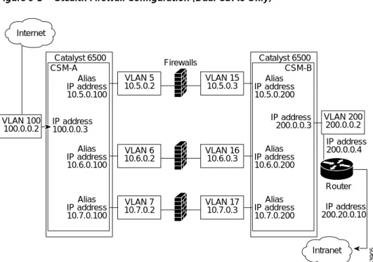
• Stealth firewalls for dual CSM configurations (Figure 5-1)
• Regular firewalls for dual CSM configurations (Figure 5-2)
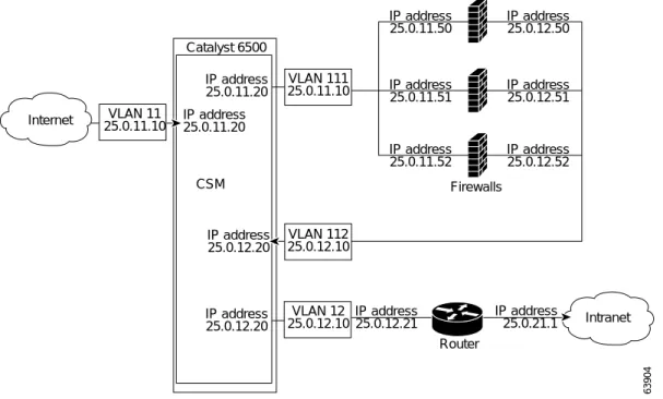
• Regular firewall for single CSM configurations (Figure 5-3)
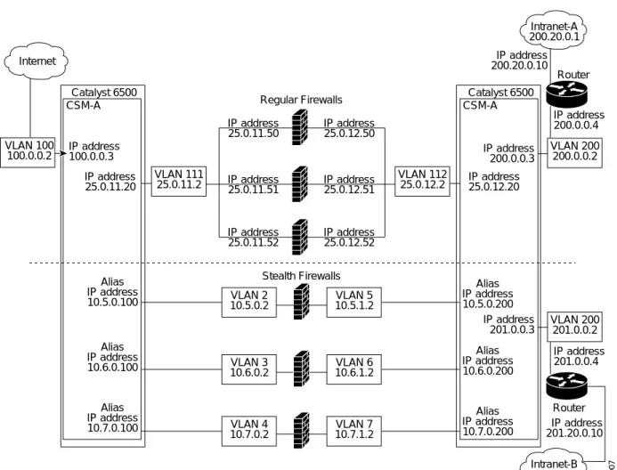
• Mixed firewalls (stealth and regular) for dual CSM configurations (Figure 5-4)
InFigure 5-1, traffic moves through the firewalls and is filtered in both directions. The figure shows the flow from the Internet to the intranet. On the path to the intranet, CSM A balances traffic across VLANs 5, 6, and 7 through firewalls to CSM B. On the path to the Internet, CSM B balances traffic across VLANs 15, 16, and 17 through firewalls to CSM A. CSM A uses the VLAN aliases of CSM B in its server farm, and CSM B uses the VLAN aliases of CSM A in its server farm.
Figure 5-1 Stealth Firewall Configuration (Dual CSMs Only)
InFigure 5-2, traffic moves through the firewalls and is filtered in both directions. The figure shows the flow from the Internet to the intranet. VLANs 11 and 111 are on the same subnet, and
VLANs 12 and 112 are on the same subnet.
Figure 5-2 Regular Firewall Configuration (Dual CSMs)
InFigure 5-3, traffic moves through the firewalls and is filtered in both directions. The figure only shows the flow from the Internet to the intranet, and VLANs 11 and 111 are on the same subnet.
VLANs 12 and 112 are on the same subnet.
VLAN 100 100.0.0.2 VLAN 5 10.5.0.2 Catalyst 6500 CSM-A IP address 200.20.0.10 IP address 200.0.0.4 Alias IP address 10.5.0.100 Alias IP address 10.6.0.100 Alias IP address 10.7.0.100 IP address 100.0.0.3 Catalyst 6500 CSM-B Alias IP address 10.5.0.200 Alias IP address 10.6.0.200 Alias IP address 10.7.0.200 IP address 200.0.0.3 Internet Intranet VLAN 6 10.6.0.2 VLAN 7 10.7.0.2 VLAN 15 10.5.0.3 VLAN 16 10.6.0.3 VLAN 200 200.0.0.2 Router Firewalls 63905 VLAN 17 10.7.0.3 VLAN 11 25.0.11.10 Catalyst 6500 CSM-A IP address 25.0.11.20 IP address 25.0.11.20 Catalyst 6500 CSM-B IP address 25.0.12.20 IP address 25.0.12.20 Internet 63906 IP address 25.0.21.1 IP address 25.0.12.1 Intranet VLAN 200 25.0.12.10 Router VLAN 111 25.0.11.10 IP address 25.0.11.50 IP address 25.0.11.51 IP address 25.0.11.52 IP address 25.0.12.50 IP address 25.0.12.51 IP address 25.0.12.52 Firewalls VLAN 112 25.0.12.10
Figure 5-3 Regular Firewall Configuration (Single CSM)
InFigure 5-4, traffic moves through both the regular and stealth firewalls and is filtered in both directions. The figure shows the flow from the Internet to the intranet. VLANs 5, 6, and 7 are shared between CSM A and CSM B. On the path to the intranet, CSM A balances traffic across VLANs 5, 6, and 7 through firewalls to CSM B. On the path to the intranet, CSM B balances traffic across VLANs 5, 6, and 7 through firewalls to CSM A.
VLAN 11 25.0.11.10 VLAN 111 25.0.11.10 IP address 25.0.11.50 IP address 25.0.11.51 IP address 25.0.11.52 IP address 25.0.12.50 IP address 25.0.12.51 IP address 25.0.12.52 VLAN 112 25.0.12.10 VLAN 12 25.0.12.10 Catalyst 6500 CSM IP address 25.0.12.20 IP address 25.0.12.21 IP address 25.0.21.1 IP address 25.0.12.20 IP address 25.0.11.20 IP address 25.0.11.20 Internet Intranet Router Firewalls 63904
Figure 5-4 Mixed Firewall Configuration for Stealth and Regular Firewalls (Dual CSMs Only)
Fault-Tolerant CSM Firewall Configurations
The CSM supports fault tolerance for these configurations:
• Stealth firewalls in a fault-tolerant dual CSM configuration
• Regular firewalls in a fault-tolerant dual CSM configuration
• Regular firewalls in a fault-tolerant single CSM configuration
• Mixed firewalls (stealth and regular) in a fault-tolerant dual CSM configuration
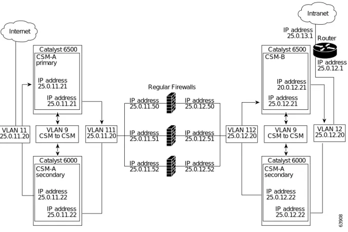
InFigure 5-5, the traffic moves through the firewalls and is filtered in both directions. The figure only shows the flow from the Internet to the intranet through the primary CSMs, and VLANs 11 and 111 are on the same subnet. VLANs 12 and 112 are on the same subnet.
VLAN 100 100.0.0.2 VLAN 2 10.5.0.2 Catalyst 6500 CSM-A IP address 201.20.0.10 IP address 201.0.0.4 Alias IP address 10.5.0.100 Alias IP address 10.6.0.100 Alias IP address 10.7.0.100 IP address 100.0.0.3 IP address 25.0.11.20 IP address 25.0.12.20 Catalyst 6500 CSM-A Alias IP address 10.5.0.200 Alias IP address 10.6.0.200 Alias IP address 10.7.0.200 IP address 200.0.0.3 IP address 201.0.0.3 Internet Intranet-B 201.20.0.1 Intranet-A 200.20.0.1 VLAN 3 10.6.0.2 VLAN 4 10.7.0.2 VLAN 5 10.5.1.2 VLAN 6 10.6.1.2 VLAN 200 201.0.0.2 VLAN 200 200.0.0.2 Router Stealth Firewalls 63907 VLAN 7 10.7.1.2 IP address 200.0.0.4 IP address 200.20.0.10 VLAN 111 25.0.11.2 IP address 25.0.11.50 IP address 25.0.11.51 IP address 25.0.11.52 IP address 25.0.12.50 IP address 25.0.12.51 IP address 25.0.12.52 Regular Firewalls VLAN 112 25.0.12.2 Router
Figure 5-5 Fault-Tolerant, Regular Firewall Configuration–(Dual CSMs)
Configuring Stealth Firewall Load Balancing
This section describes how to configure firewall load balancing for stealth firewalls and covers the following information:
• Packet flow in a stealth firewall configuration (dual CSMs)
• Stealth firewall configuration example
Stealth Firewall Configuration
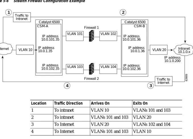
In a stealth firewall configuration, firewalls connect to two different VLANs and are configured with IP addresses on the VLANs to which they connect. (SeeFigure 5-6.)
Catalyst 6500 CSM-A primary IP address 25.0.11.21 IP address 25.0.11.21 Catalyst 6000 CSM-A secondary IP address 25.0.11.22 IP address 25.0.11.22 IP address 25.0.12.21 Catalyst 6500 CSM-B IP address 20.0.12.21 Internet Intranet VLAN 12 25.0.12.20 63908 IP address 25.0.12.1 IP address 25.0.13.1 VLAN 111 25.0.11.20 VLAN 9 CSM to CSM IP address 25.0.11.50 IP address 25.0.11.51 IP address 25.0.11.52 IP address 25.0.12.50 IP address 25.0.12.51 IP address 25.0.12.52 Regular Firewalls VLAN 112 25.0.12.20 VLAN 11 25.0.11.20 Catalyst 6000 CSM-A secondary IP address 25.0.12.22 IP address 25.0.12.22 VLAN 9 CSM to CSM Router
Figure 5-6 Stealth Firewall Configuration Example
Figure 5-6 shows two regular firewalls (Firewall 1 and Firewall 2) sandwiched between two CSMs (CSM A and CSM B).
Note Stealth firewalls do not have addresses on VLANs.
On the path from the Internet to the intranet, traffic enters the insecure side of the firewalls through separate VLANs, VLAN 101 and VLAN 103, and exits the secure side of the firewalls through separate VLANs, VLAN 102 and VLAN 104. On the path from the intranet to the Internet, the flow is reversed. VLANs also provide connectivity to the Internet (VLAN 10) and to the intranet (VLAN 20).
In a stealth configuration, CSM A and CSM B load balance traffic through the firewalls.
Stealth Firewall Configuration Example
The stealth firewall configuration example contains two CSMs (CSM A and CSM B) installed in separate Catalyst 6000 family switches.
Note In a stealth firewall configuration, each CSM must be installed in a separate Catalyst 6000 family switch. VLAN 10 VLAN 20 Catalyst 6500 CSM-A IP address 10.0.101.35 IP address 10.0.101.36 IP address 10.0.102.36 IP address 10.1.0.200 IP address 10.0.102.35 IP address 10.0.1.35 IP address10.0.1.36 Catalyst 6500 CSM-B Internet 63909 Intranet 10.1.0.x VLAN 101 VLAN 103 VLAN 102 Firewall 1 Firewall 2 VLAN 104 Traffic to Intranet Traffic to Internet 1 2 3 4
Location Traffic Direction Arrives On Exits On
1 To intranet VLAN 10 VLANs 101 and 103
2 To intranet VLANs 101 and 103 VLAN 20
3 To Internet VLAN 20 VLANs 102 and 104
This section describes how to create the stealth firewall configuration for CSM A and CSM B.
Configuring CSM A (Stealth Firewall Example)
To create the regular configuration example, perform these tasks for CSM A:
• Creating VLANs on Switch A, page 5-10 • Configuring VLANs on CSM A, page 5-10 • Configuring Server Farms on CSM A, page 5-11 • Configuring Virtual Servers on CSM A, page 5-12
Note Although the configuration tasks are the same for both for CSM A and CSM B, the steps, commands, and parameters that you enter are different.
Creating VLANs on Switch A
To create two VLANs on switch A, perform this task:
Configuring VLANs on CSM A
To configure the three VLANs, perform this task:
Command Purpose
Step 1 Switch-A(config)# vlan database Enters the VLAN mode.1
1. Do this step on the switch console of the switch that contains CSM A.
Step 2 Switch-A(vlan)# vlan 10 Creates VLAN 102.
2. VLAN 10 connects CSM A to the Internet.
Step 3 Switch-A(vlan)# vlan 101 Creates VLAN 1013.
3. VLAN 101 provides a connection through Firewall 1 to CSM B.
Step 4 Switch-A(vlan)# vlan 103 Creates VLAN 1034.
4. VLAN 103 provides a connection through Firewall 2 to CSM B
Command Purpose
Step 1 Switch-A(config)# module csm 5 Enters multiple module configuration mode and
specifies that CSM A is installed in slot 5.
Step 2 Switch-A(config-module-csm)# vlan 10
client
Specifies VLAN 10 as the VLAN that is being configured, identifies it as a client VLAN, and enters VLAN configuration mode.
Step 3 Switch-A(config-slb-vlan-client)# ip
address 10.0.1.35 255.255.255.0
Specifies an IP address and netmask for VLAN 10.
Step 4 Switch-A(config-slb-vlan-client)# alias
10.0.1.30 255.255.255.0
Specifies an alias IP address and netmask for VLAN 101.
Step 5 Switch-A(config-slb-vlan-client)# exit Returns to VLAN configuration mode.
Step 6 Switch-A(config-module-csm)# vlan 101
server
Specifies VLAN 101 as the VLAN that is being configured, identifies it as a server VLAN, and enters VLAN configuration mode.
Configuring Server Farms on CSM A
Note Because the IP addresses of CSM B are listed in the INSIDE-SF server farm as real servers, CSM A will load balance the two firewalls that exist in the path to CSM B.
To configure two server farms on CSM A, perform this task:
Step 7 Switch-A(config-slb-vlan-server)# ip
address 10.0.101.35 255.255.255.0
Specifies an IP address and netmask for VLAN 101.
Step 8 Switch-A(config-slb-vlan-server)# alias
10.0.101.100 255.255.255.0
Specifies an alias IP address and netmask for VLAN 1011.
Step 9 Switch-A(config-slb-vlan-server)# exit Returns to VLAN configuration mode.
Step 10 Switch-A(config-module-csm)# vlan 103
server
Specifies VLAN 103 as the VLAN that is being configured, identifies it as a server VLAN, and enters VLAN configuration mode.
Step 11 Switch-A(config-slb-vlan)# ip address
10.0.102.35 255.255.255.0
Specifies an IP address and netmask for VLAN 103.
Step 12 Switch-A(config-slb-vlan)# alias
10.0.102.100 255.255.255.0
Specifies an alias IP address and netmask for VLAN 1031.
1. This step provides a target for CSM B to use in making a load-balancing decision.
Command Purpose
Command Purpose
Step 1 Switch-A(config)# module csm 5 Enters multiple module configuration mode and
specifies that CSM A is installed in slot 5.
Step 2 Switch-A(config-module-csm)# serverfarm
FORWARD-SF
Creates and names the FORWARD-SF1server farm (actually a forwarding policy) and enters server farm configuration mode.
Step 3 Switch-A(config-slb-sfarm)# no nat server Disables the NAT of server IP addresses and port
numbers2.
Step 4 Switch-A(config-slb-sfarm)# predictor
forward
Forwards traffic in accordance with its internal routing tables rather than a load-balancing algorithm.
Step 5 Switch-A(config-slb-sfarm)# exit Returns to multiple module configuration mode.
Step 6 Switch-A(config-module-csm)# serverfarm
TO-INSIDE-SF
Creates and names the INSIDE-SF3server farm (that will contain alias IP addresses rather than real servers) and enters server farm configuration mode.
Step 7 Switch-A(config-slb-sfarm)# no nat server Disables the NAT of server IP address and port
number4.
Step 8 Switch-A(config-slb-sfarm)# predictor
hash address source 255.255.255.255
Selects a server using a hash value based on the source IP address5.
Step 9 Switch-A(config-slb-sfarm)# real
10.0.101.200
Identifies the alias IP address of CSM B that lies on the path to Firewall 1 as a real server and enters real server configuration submode.
Configuring Virtual Servers on CSM A
To configure three virtual servers on CSM A, perform this task:
Step 11 Switch-A(config-slb-real)# exit Returns to server farm configuration mode.
Step 12 Switch-A(config-slb-sfarm)# real
10.0.102.200
Identifies the alias IP address of CSM B that lies on the path to Firewall 2 as a real server and enters real server configuration submode.
Step 13 Switch-A(config-slb-real)# inservice Enables the firewall.
1. FORWARD-SF is actually a route forwarding policy, not an actual server farm, that allows traffic to reach the Internet (through VLAN 10). It does not contain any real servers.
2. This step is required when configuring a server farm that contains a forwarding policy rather than real servers.
3. INSIDE-SF contains the two alias IP addresses of CSM B listed as real servers that allow traffic from the intranet to reach CSM B.
4. This step is required when configuring a server farm that contains firewalls.
5. We recommend this step when configuring insecure-side firewall interfaces in a server farm.
Command Purpose
Command Purpose
Step 1 Switch-A(config)# module csm 5 Enters multiple module configuration mode and
specifies that the CSM A is installed in slot 5.
Step 2 Switch-A(config-module-csm)# vserver
FORWARD-V101
Specifies FORWARD-V1011 as the virtual server that is being configured and enters virtual server configuration mode.
Step 3 Switch-A(config-slb-vserver)# virtual
0.0.0.0 0.0.0.0 any
Specifies a match for any IP address and any protocol2.
Step 4 Switch-A(config-slb-vserver))# vlan 101 Specifies that the virtual server will only accept
traffic arriving on VLAN 101, which is traffic arriving from the insecure side of the firewalls.
Step 5 Switch-A(config-slb-vserver)# serverfarm
FORWARD-SF
Specifies the server farm for this virtual server3.
Step 6 Switch-A(config-slb-vserver)# inservice Enables the virtual server.
Step 7 Switch-A(config-slb-vserver)# exit Returns to multiple module configuration mode.
Step 8 Switch-A(config-module-csm)# vserver
FORWARD-V103
Specifies FORWARD-V1034 as the virtual server
that is being configured and enters virtual server configuration mode.
Step 9 Switch-A(config-slb-vserver)# virtual
0.0.0.0 0.0.0.0 any
Specifies a match for any IP address and any protocol5.
Step 10 Switch-A(config-slb-vserver))# vlan 103 Specifies that the virtual server will only accept
traffic arriving on VLAN 103, which is traffic arriving from the insecure side of the firewalls.
Step 11 Switch-A(config-slb-vserver)# serverfarm
FORWARD-SF
Specifies the server farm for this virtual server3.
Step 12 Switch-A(config-slb-vserver)# inservice Enables the virtual server.
Configuring CSM B (Stealth Firewall Example)
To create the regular configuration example, perform the following configuration tasks for CSM B:
• Creating VLANs on Switch B, page 5-13 • Configuring VLANs on CSM B, page 5-14 • Configuring Server Farms on CSM B, page 5-14 • Configuring Virtual Servers on CSM B, page 5-16
Note Although the configuration tasks are the same for both CSM A and CSM B, the steps, commands, and parameters that you enter are different.
Creating VLANs on Switch B
To create three VLANs on Switch B, perform this task:
Note This example assumes that the CSMs are in separate Catalyst 6000 family switches. If they are in the same chassis, you can create all of the VLANs on the same Catalyst 6000 family switch console.
Step 14 Switch-A(config-module-csm)# vserver
OUTSIDE-VS
Specifies OUTSIDE-VS6as the virtual server that is being configured and enters virtual server
configuration mode.
Step 15 Switch-A(config-slb-vserver)# virtual
10.1.0.0 255.255.255.0 any
Specifies the IP address, netmask, and protocol (any) for this virtual server. Clients reach the server farm represented by this virtual server through this address.
Step 16 Switch-A(config-slb-vserver))# vlan 10 Specifies that the virtual server will only accept
traffic arriving on VLAN 10, which is traffic arriving from the Internet.
Step 17 Switch-A(config-slb-vserver)# serverfarm
TO-INSIDE-SF
Specifies the server farm for this virtual server7.
Step 18 Switch-A(config-slb-vserver)# inservice Enables the virtual server.
1. FORWARD-V101 allows Internet traffic to reach the insecure side of the firewalls (through VLAN 101). 2. Client matching is only limited by VLAN restrictions (see Step 4).
3. This server farm is actually a forwarding predictor rather than an actual server farm containing real servers. 4. FORWARD-V103 allows Internet traffic to reach the insecure side of the firewalls (through VLAN 103). 5. Clients will always match–only being limited by VLAN restrictions. (See Step 10.)
6. OUTSIDE-VS allows traffic from the Internet to reach CSM A (through VLAN 10).
7. The server farm contains the alias IP addresses of CSM B that lie along the path of Firewall 1 and Firewall 2.
Command Purpose
Command Purpose
Step 1 Switch-B(config)# vlan database Enters the VLAN mode1.
Configuring VLANs on CSM B
To configure the three VLANs, perform this task:
Configuring Server Farms on CSM B
To configure three server farms on CSM B, perform this task:
Note SERVERS-SF specifies that client NAT will be performed using a pool of client NAT addresses that are created earlier in the example using the natpool command. You must create the NAT pool before referencing the command.
Step 3 Switch-B(vlan)# vlan 104 Creates VLAN 1043.
Step 4 Switch-B(vlan)# vlan 200 Creates VLAN 2004.
1. Do this step on the switch console of the switch that contains CSM B. 2. VLAN 102 provides a connection through Firewall 1 to CSM A. 3. VLAN 104 provides a connection through Firewall 2 to CSM A. 4. VLAN 200 provides the connection to the internal network.
Command Purpose
Command Purpose
Step 1 Switch-B(config)# module csm 6 Enters multiple module configuration mode and
specifies that CSM B is installed in slot 6.
Step 2 Switch-B(config-module-csm)# vlan 102
server
Specifies VLAN 102 as the VLAN that is being configured, identifies it as a server VLAN, and enters VLAN configuration mode.
Step 3 Switch-B(config-slb-vlan-server)# ip
address 10.0.101.36 255.255.255.0
Specifies an IP address and netmask for VLAN 102.
Step 4 Switch-B(config-slb-vlan-server)# alias
10.0.101.200 255.255.255.0
Specifies an alias IP address and netmask for VLAN 1021.
1. This step provides a target for CSM A to use in making a load-balancing decision.
Step 5 Switch-B(config-slb-vlan-server)# exit Returns to multiple module configuration mode.
Step 6 Switch-B(config-module-csm)# vlan 104
server
Specifies VLAN 104 as the VLAN that is being configured, identifies it as a server VLAN, and enters VLAN configuration mode.
Step 7 Switch-B(config-slb-vlan-server)# ip
address 10.0.102.36 255.255.255.0
Specifies an IP address and netmask for VLAN 104.
Step 8 Switch-B(config-slb-vlan)# alias
10.0.102.200 255.255.255.0
Specifies an alias IP address and netmask for VLAN 1041.
Step 9 Switch-B(config-slb-vlan-server)# exit Returns to multiple module configuration mode.
Step 10 Switch-B(config-module-csm)# vlan 20
server
Specifies VLAN 20 as the VLAN that is being configured, identifies it as a server VLAN, and enters VLAN configuration mode.
Step 11 Switch-B(config-slb-vlan-server)# ip
address 10.1.0.36 255.255.255.0
Command Purpose
Step 1 Switch-B(config)# module csm 6 Enters multiple module configuration mode and
specifies that CSM B is installed in slot 6.
Step 2 Switch-B(config-module-csm)# serverfarm
FORWARD-SF
Creates and names the FORWARD-SF1server farm (actually a forwarding policy) and enters server farm configuration mode.
Step 3 Switch-B(config-slb-sfarm)# no nat server Disables the NAT of server IP addresses and port
numbers2.
Step 4 Switch-B(config-slb-sfarm)# predictor
forward
Forwards traffic in accordance with its internal routing tables rather than a load-balancing algorithm.
Step 5 Switch-B(config-slb-sfarm)# exit Returns to multiple module configuration mode.
Step 6 Switch-B(config-module-csm)# serverfarm
TO-OUTSIDE-SF
Creates and names the GENERIC-SF server farm and enters server farm configuration mode3.
Step 7 Switch-B(config-slb-sfarm)# no nat server Disables NAT of server IP addresses and port
numbers4.
Step 8 Switch-B(config-slb-sfarm)# real
10.0.101.100
Identifies the alias IP address of CSM A that lies on the path to Firewall 1 as a real server and enters real server configuration submode.
Step 9 Switch-B(config-slb-real)# inservice Enables the real (actually an alias IP address).
Step 10 Switch-B(config-slb-real)# exit Returns to server farm configuration mode.
Step 11 Switch-B(config-slb-sfarm)# real
10.0.102.100
Identifies the alias IP address of CSM B that lies on the path to Firewall 2 as a real server and enters real server configuration submode.
Step 12 Switch-B(config-slb-real)# inservice Enables the real server (actually an alias IP address).
Step 13 Switch-B(config-slb-real)# exit Returns to server farm configuration mode.
Step 14 Switch-B(config-module-csm)# serverfarm
SERVERS-SF
Creates and names the SERVERS-SF5 server farm and enters serverfarm configuration mode.
Step 15 Switch-B(config-slb-sfarm)# real
10.1.0.101
Identifies a server in the intranet as a real server, assigns it an IP address, and enters real server configuration submode.
Step 16 Switch-B(config-slb-real)# inservice Enables the real server.
Step 17 Switch-B(config-slb-real)# exit Returns to server farm configuration mode.
Step 18 Switch-B(config-slb-sfarm)# real
10.1.0.102
Identifies a server in the intranet as a real server, assigns it an IP address, and enters real server configuration submode.
Configuring Virtual Servers on CSM B
To configure three virtual servers on CSM, perform this task:
Step 20 Switch-B(config-slb-sfarm)# real
10.1.0.103
Identifies a server in the intranet as a real server, assigns it an IP address, and enters real server configuration submode.
Step 21 Switch-B(config-slb-real)# inservice Enables the real server.
1. FORWARD-SF is actually a route forwarding policy, not an actual server farm, that allows traffic to reach the intranet (through VLAN 20). It does not contain any real servers.
2. This is a required step when configuring a server farm that contains a forwarding policy rather than real servers. 3. OUTSIDE-SF contains the two alias IP addresses of CSM A as the real servers allowing traffic from the intranet to reach
CSM A.
4. This is a required step when configuring a server farm that contains a forwarding policy rather than real servers. 5. SERVERS-SF contains the IP addresses of the real servers located within the intranet.
Command Purpose
Command Purpose
Step 1 Switch-B(config)# module csm 6 Enters multiple module configuration mode and
specifies that CSM B is installed in slot 6.
Step 2 Switch-B(config-module-csm)# vserver
FORWARD-VS-102
Specifies FORWARD-VS as the virtual server that is being configured and enters virtual server
configuration mode.
Step 3 Switch-B(config-slb-vserver)# virtual
0.0.0.0 0.0.0.0 any
Specifies a match for any IP address and any protocol1.
Step 4 Switch-B(config-slb-vserver)# vlan 102 Specifies that the virtual server will only accept
traffic arriving on VLAN 102, which is traffic arriving from the secure side of the Firewall 1.
Step 5 Switch-B(config-slb-vserver)# serverfarm
FORWARD-SF
Specifies the server farm for this virtual server2.
Step 6 Switch-B(config-slb-vserver)# inservice Enables the virtual server.
Step 7 Switch-B(config-slb-vserver)# exit Returns to multiple module configuration mode.
Step 8 Switch-B(config-module-csm)# vserver
FORWARD-VS-104
Specifies FORWARD-VS3 as the virtual server that is being configured and enters virtual server configuration mode.
Step 9 Switch-B(config-slb-vserver)# virtual
0.0.0.0 0.0.0.0 any
Specifies a match for any IP address and any protocol1.
Step 10 Switch-B(config-slb-vserver)# vlan 104 Specifies that the virtual server will only accept
traffic arriving on VLAN 104, which is traffic arriving from the secure side of the Firewall 2.
Step 11 Switch-B(config-slb-vserver)# serverfarm
FORWARD-SF
Specifies the server farm for this virtual server2.
Step 12 Switch-B(config-slb-vserver)# inservice Enables the virtual server.
Configuring Regular Firewall Load Balancing
This section describes how to configure firewall load balancing for regular firewalls and provides the following information:
• Packet flow in a regular firewall configuration (dual CSMs)
• Regular firewall configuration example
Step 14 Switch-B(config-module-csm)# vserver
INSIDE-VS
Specifies INSIDE-VS4 as the virtual server that is being configured and enters virtual server configuration mode.
Step 15 Switch-B(config-slb-vserver)# virtual
0.0.0.0 0.0.0.0 any
Specifies a match for any IP address and any protocol1.
Step 16 Switch-B(config-slb-vserver)# vlan 20 Specifies that the virtual server will only accept
traffic arriving on VLAN 20, which is traffic arriving from the intranet.
Step 17 Switch-B(config-slb-vserver)# serverfarm
TO-OUTSIDE-SF
Specifies the server farm for this virtual server (containing the alias IP addresses of CSM A as real servers and allowing traffic to flow through Firewalls 1 and 2) and enters real server configuration submode.
Step 18 Switch-B(config-slb-vserver)# inservice Enables the virtual server.
Step 19 Switch-B(config-slb-vserver)# exit Returns to multiple module configuration mode.
Step 20 Switch-B(config-module-csm)# vserver
TELNET-VS
Specifies TELNET-VS5 as the virtual server that is being configured and enters virtual server
configuration mode.
Note TELNET-VS does not use a VLAN limit; any source traffic (from firewalls or internal network) will be load balanced through this address.
Step 21 Switch-B(config-slb-vserver)# virtual
10.1.0.200 255.255.255.0 tcp telnet
Specifies the IP address, netmask, protocol (TCP), and port (Telnet) for this virtual server6.
Step 22 Switch-B(config-slb-vserver)# serverfarm
SERVERS-SF
Specifies the server farm containing real servers for this virtual server.
Step 23 Switch-B(config-slb-vserver)# inservice Enables the virtual server.
1. Client matching is only limited by VLAN restrictions.
2. This server farm is actually a forwarding predictor rather than an actual server farm containing real servers. 3. FORWARD-VS allows traffic from the Internet to reach the intranet through VLAN 20.
4. INSIDE-VS allows traffic from the intranet to reach CSM A through Firewall 1 (through VLANs 102 and 101) or Firewall 2 (through VLANs 104 and 103).
5. TELNET-VS allows traffic from the Internet to reach Telnet servers in the internal network. 6. Clients reach the server farm represented by this virtual server through this address.
Packet Flow in a Regular Firewall Configuration
In a regular firewall configuration, firewalls connect to two different VLANs and are configured with IP addresses on the VLANs to which they connect. (SeeFigure 5-7.)
Figure 5-7 Regular Firewall Configuration Example
Figure 5-7 shows two regular firewalls (Firewall 1 and Firewall 2) located between two CSMs (CSM A and CSM B). Traffic enters and exits the firewalls through shared VLANs (VLAN 101 and VLAN 201). Both regular firewalls have unique addresses on each shared VLAN.
VLANs provide connectivity to the Internet (VLAN 100), the internal network (VLAN 200), and to internal server farms (VLAN 20).
The CSM balances traffic among regular firewalls as if they were real servers. Regular firewalls are configured in server farms with IP addresses like real servers. The server farms to which regular firewalls belong are assigned a load-balancing predictor and are associated with virtual servers.
VLAN 100 VLAN 20 Catalyst 6500 CSM-A IP address 10.1.0.26 IP address 200.0.0.x IP address 100.0.0.25 IP address 100.0.0.3 IP address 100.0.0.4 IP address 200.0.0.3 IP address 200.0.0.4 IP address 200.0.0.26 Catalyst 6500 CSM-B Internet 63910 VLAN 101 VLAN 201 VLAN 200 Firewall 1 Firewall 2 Traffic to Intranet Traffic to Internet 1 2 3 4 IP address 10.1.0.x Internal network IP address 200.0.0.x IP address 100.0.0.13 Router
Item Traffic Direction Arrives On Exits On
1 To intranet VLAN 100 VLANs 101
2 To intranet VLANs 201 VLAN 200 and 20
3 To Internet VLAN 200 and 20 VLANs 201
Regular Firewall Configuration Example
The regular firewall configuration example contains two CSMs (CSM A and CSM B) installed in separate Catalyst 6000 family switches.
Note You can use this example when configuring two CSMs in the same Catalyst 6000 family switch chassis. You can also use this example when configuring a single CSM in a single switch chassis, assuming that you specify the slot number of that CSM when configuring both CSM A and CSM B.
Configuring CSM A (Regular Firewall Example)
To create the regular configuration example, perform the following configuration tasks for CSM A:
• Creating VLANs on Switch A, page 5-19 • Configuring VLANs on CSM A, page 5-20 • Configuring Server Farms on CSM A, page 5-20 • Configuring Virtual Servers on CSM A, page 5-21
Note Although the configuration tasks are the same for both CSM A and CSM B, the steps, commands, and parameters that you enter are different.
Creating VLANs on Switch A
The example, shown inFigure 5-7, requires that you create two VLANs on Switch A.
Note This example assumes that the CSMs are in separate Catalyst 6000 family switch chassis. If they are in the same chassis, all of the VLANs can be created on the same Catalyst 6000 family switch console.
To configure VLANs on Switch A, perform this task:
Command Purpose
Step 1 Switch-A(config)# vlan database Enters the VLAN mode1.
1. Do this step on the switch console of the switch that contains CSM A.
Step 2 Switch-A(vlan)# vlan 100 Creates VLAN 1002.
2. VLAN 100 connects CSM A to the Internet.
Step 3 Switch-A(vlan)# vlan 101 Creates VLAN 1013.
Configuring VLANs on CSM A
To configure the two VLANs, perform this task:
Configuring Server Farms on CSM A
Note Firewall 1 and Firewall 2 secure-side IP addresses are configured as real servers in the SEC-SF server farm associated with CSM B.
To configure two server farms on CSM A, perform this task:
Command Purpose
Step 1 Switch-A(config)# module csm 5 Enters multiple module configuration mode and
specifies that CSM A is installed in slot 5.
Step 2 Switch-A(config-module-csm)# vlan 100
client
Specifies VLAN 100 as the VLAN that is being configured, identifies it as a client VLAN, and enters VLAN configuration mode.
Step 3 Switch-A(config-slb-vlan-client)# ip
address 100.0.0.25 255.255.255.0
Specifies an IP address and netmask for VLAN 100.
Step 4 Switch-A(config-slb-vlan-client)# gateway
100.0.0.13
Configures a gateway IP address for the router on the Internet side of CSM A.
Step 5 Switch-A(config-slb-vlan-client)# exit Returns to multiple module configuration mode.
Step 6 Switch-A(config-module-csm)# vlan 101
server
Specifies VLAN 101 as the VLAN that is being configured, identifies it as a server VLAN, and enters VLAN configuration mode.
Step 7 Switch-A(config-slb-vlan-server)# ip
address 100.0.0.25 255.255.255.0
Specifies an IP address and netmask for VLAN 101.
Step 8 Switch-A(config-slb-vlan-server)# alias
100.0.0.20 255.255.255.0
Specifies an alias IP address and netmask for VLAN 1011.
1. This step provides a target for CSM B to use in making a load-balancing decision.
Command Purpose
Step 1 Switch-A(config)# module csm 5 Enters multiple module configuration mode and
specifies that CSM A is installed in slot 5.
Step 2 Switch-A(config-module-csm)# serverfarm
FORWARD-SF
Creates and names the FORWARD-SF1server farm (actually a forwarding policy) and enters server farm configuration mode.
Step 3 Switch-A(config-slb-sfarm)# no nat server Disables the NAT of server IP addresses and port
numbers2.
Step 4 Switch-A(config-slb-sfarm)# predictor
forward
Forwards traffic by adhering to its internal routing tables rather than a load-balancing algorithm.
Step 5 Switch-A(config-slb-sfarm)# exit Returns to multiple module configuration mode.
Step 6 Switch-A(config-module-csm)# serverfarm
INSEC-SF
Creates and names the INSEC-SF3 server farm (which will contain firewalls as real servers) and enters server farm configuration mode.
Configuring Virtual Servers on CSM A
To configure two virtual servers on CSM A, perform this task:
Step 7 Switch-A(config-slb-sfarm)# no nat server Disables the NAT of server IP address and port
number4.
Step 8 Switch-A(config-slb-sfarm)# predictor
hash address source 255.255.255.255
Selects a server using a hash value based on the source IP address5.
Step 9 Switch-A(config-slb-sfarm)# real
100.0.0.3
Identifies Firewall 1 as a real server, assigns an IP address to its insecure side, and enters real server configuration submode.
Step 10 Switch-A(config-slb-real)# inservice Enables the firewall.
Step 11 Switch-A(config-slb-real)# exit Returns to server farm configuration mode.
Step 12 Switch-A(config-slb-sfarm)# real
100.0.0.4
Identifies Firewall 2 as a real server, assigns an IP address to its insecure side, and enters real server configuration submode.
Step 13 Switch-A(config-slb-real)# inservice Enables the firewall.
1. FORWARD-SF is actually a route forwarding policy, not an actual server farm, that allows traffic to reach the Internet (through VLAN 100); it does not contain any real servers.
2. This is a required step when configuring a server farm that contains a forwarding policy rather than real servers. 3. INSEC-SF contains (Firewall 1 and Firewall 2); their insecure-side IP addresses are configured as real servers in this server
farm.
4. This is a required step when configuring a server farm that contains firewalls.
5. We recommend this step when configuring insecure-side firewall interfaces in a server farm.
Command Purpose
Command Purpose
Step 1 Switch-A(config)# module csm 5 Enters multiple module configuration mode and
specifies that the CSM A is installed in slot 5.
Step 2 Switch-A(config-module-csm)# vserver
FORWARD-VS
Specifies FORWARD-VS1 as the virtual server that is being configured and enters virtual server configuration mode.
Step 3 Switch-A(config-slb-vserver)# virtual
0.0.0.0 0.0.0.0 any
Specifies a match for any IP address and any protocol2.
Step 4 Switch-A(config-slb-vserver))# vlan 101 Specifies that the virtual server will only accept
traffic arriving on VLAN 101, which is traffic arriving from the insecure side of the firewalls.
Step 5 Switch-A(config-slb-vserver)# serverfarm
FORWARD-SF
Specifies the server farm for this virtual server3.
Step 6 Switch-A(config-slb-vserver)# inservice Enables the virtual server.
Step 7 Switch-A(config-slb-vserver)# exit Returns to multiple module configuration mode.
Step 8 Switch-A(config-module-csm)# vserver
INSEC-VS
Specifies INSEC-VS4 as the virtual server that is
being configured and enters virtual server configuration mode.
Step 9 Switch-A(config-slb-vserver)# virtual
200.0.0.0 255.255.255.0 any
Specifies the IP address, netmask, and protocol (any) for this virtual server5.
Configuring CSM B (Regular Firewall Example)
To create the regular configuration example, perform the following configuration tasks for CSM B:
• Creating VLANs on Switch B, page 5-22 • Configuring VLANs on CSM B, page 5-23 • Configuring Server Farms on CSM B, page 5-23 • Configuring Virtual Servers on CSM B, page 5-24
Note Although the configuration tasks are the same for both CSM A and CSM B, the steps, commands, and parameters that you enter are different.
Creating VLANs on Switch B
Note This example assumes that the CSMs are in separate Catalyst 6000 family switch chassis. If they are in the same chassis, all of the VLANs can be created on the same Catalyst 6000 family switch console.
To create three VLANs on Switch B, perform this task:
Step 10 Switch-A(config-slb-vserver))# vlan 100 Specifies that the virtual server will only accept
traffic arriving on VLAN 100, which is traffic arriving from the Internet.
Step 11 Switch-A(config-slb-vserver)# serverfarm
INSEC-SF
Specifies the server farm for this virtual server6.
Step 12 Switch-A(config-slb-vserver)# inservice Enables the virtual server.
1. FORWARD-VS allows Internet traffic to reach the insecure side of the firewalls (through VLAN 101). 2. Client matching is only limited by VLAN restrictions (see Step 4).
3. This server farm is actually a forwarding predictor rather than an actual server farm containing real servers. 4. INSEC-VS allows traffic from the Internet to reach CSM A (through VLAN 101).
5. Clients reach the server farm represented by this virtual server through this address. 6. The server farm contains firewalls rather than real servers.
Command Purpose
Command Purpose
Step 1 Switch-B(config)# vlan database Enters the VLAN mode1.
1. Do this step on the switch console of the switch that contains CSM B.
Step 2 Switch-B(vlan)# vlan 201 Creates VLAN 2012.
2. VLAN 201 provides the connection to the secure side of the firewalls.
Step 3 Switch-B(vlan)# vlan 200 Creates VLAN 2003.
3. VLAN 20 provides the connection to the internal server farms.
Step 4 Switch-B(vlan)# vlan 20 Creates VLAN 204.
Configuring VLANs on CSM B
To configure the three VLANs on CSM B, perform this task:
Configuring Server Farms on CSM B
Note Firewall 1 and Firewall 2 secure-side IP addresses are configured as real servers in the INSEC-SF server farm associated with CSM A.
To configure two server farms on CSM B, perform this task:
Command Purpose
Step 1 Switch-B(config)# module csm 6 Enters multiple module configuration mode and
specifies that CSM B is installed in slot 6.
Step 2 Switch-B(config-module-csm)# vlan 201
server
Specifies VLAN 201 as the VLAN that is being configured, identifies it as a server VLAN, and enters VLAN configuration mode.
Step 3 Switch-B(config-slb-vlan-server)# ip
address 200.0.0.26 255.255.255.0
Specifies an IP address and netmask for VLAN 201.
Step 4 Switch-B(config-slb-vlan-server)# alias
200.0.0.20 255.255.255.0
Specifies an alias IP address and netmask for VLAN 2011.
1. This step provides a target for CSM A to use in making a load-balancing decision.
Step 5 Switch-B(config-slb-vlan-server)# exit Returns to VLAN configuration mode.
Step 6 Switch-B(config-module-csm)# vlan 20
server
Specifies VLAN 20 as the VLAN that is being configured, identifies it as a server VLAN, and enters VLAN configuration mode.
Step 7 Switch-B(config-slb-vlan-server)# ip
address 10.1.0.26 255.255.255.0
Specifies an IP address and netmask for VLAN 20.
Step 8 Switch-B(config-slb-vlan-server)# exit Returns to VLAN configuration mode.
Step 9 Switch-B(config-module-csm)# vlan 200
client
Specifies VLAN 200 as the VLAN that is being configured, identifies it as a client VLAN, and enters VLAN configuration mode.
Step 10 Switch-B(config-slb-vlan)# ip address
200.0.0.26 255.255.255.0
Specifies an IP address and netmask for VLAN 200.
Command Purpose
Step 1 Switch-B(config)# module csm 6 Enters multiple module configuration mode and
specifies that CSM B is installed in slot 6.
Step 2 Switch-B(config-module-csm)# serverfarm
GENERIC-SF
Creates and names the GENERIC-SF1 server farm and enters server farm configuration mode.
Step 3 Switch-B(config-slb-sfarm)# real
10.1.0.101
Identifies a server in the internal server farm as a real server, assigns it an IP address, and enters real server configuration submode.
Step 4 Switch-B(config-slb-real)# inservice Enables the real server.
Configuring Virtual Servers on CSM B
To configure three virtual servers on CSM B, perform this task:
Step 6 Switch-B(config-slb-sfarm)# real
10.1.0.102
Identifies a server in the internal server farm as a real server, assigns it an IP address, and enters real server configuration submode.
Step 7 Switch-B(config-slb-real)# inservice Enables the real server.
Step 8 Switch-B(config-slb-real)# exit Returns to server farm configuration mode.
Step 9 Switch-B(config-slb-sfarm)# exit Returns to multiple module configuration mode.
Step 10 Switch-B(config-module-csm)# serverfarm
SEC-SF
Creates and names the SEC-SF2 server farm and enters server farm configuration mode.
Step 11 Switch-B(config-slb-sfarm)# no nat server Disables the NAT of server IP address and port
number3.
Step 12 Switch-B(config-slb-sfarm)# predictor
hash address destination 255.255.255.255
Selects a server using a hash value based on the destination IP address4.
Step 13 Switch-B(config-slb-sfarm)# real
200.0.0.3
Identifies Firewall 1 as a real server, assigns an IP address to its insecure side, and enters real server configuration submode.
Step 14 Switch-B(config-slb-real)# inservice Enables the firewall.
Step 15 Switch-B(config-slb-real)# exit Returns to server farm configuration mode.
Step 16 Switch-B(config-slb-sfarm)# real
200.0.0.4
Identifies Firewall 2 as a real server, assigns an IP address to its insecure side, and enters real server configuration submode.
Step 17 Switch-B(config-slb-real)# inservice Enables the firewall.
1. GENERIC-SF contains the real servers in the internal server farm.
2. SEC-SF contains (firewall 1 and firewall 2)–their secure-side IP addresses are configured as real servers in this server farm. 3. This is a required step when configuring a server farm that contains firewalls.
4. We recommend this step when configuring secure-side firewall interfaces in a server farm.
Command Purpose
Command Purpose
Step 1 Switch-B(config)# module csm 6 Enters multiple module configuration mode and
specifies that CSM B is installed in slot 6.
Step 2 Switch-B(config-module-csm)# vserver
GENERIC-VS
Specifies GENERIC-VS1as the virtual server that is being configured and enters virtual server
configuration mode.
Step 3 Switch-B(config-slb-vserver)# virtual
200.0.0.127 tcp 0
Specifies the IP address, protocol (TCP), and port (0=any) for this virtual server2.
Step 4 Switch-B(config-slb-vserver))# vlan 201 Specifies that the virtual server will only accept
traffic arriving on VLAN 201, which is traffic arriving from the secure side of the firewalls.
Step 5 Switch-B(config-slb-vserver)# serverfarm
GENERIC-SF
Specifies the server farm for this virtual server3.
Configuring Generic Header Parsing
In software release 2.1(1), the CSM supports generic HTTP request header parsing. The HTTP request header contains fields that describe how content should be formatted to meet the user’s requirements. The CSM uses the information it learns by parsing and matching fields in the HTTP header along with policy information to make load-balancing decisions. For example, by parsing the browser-type field in the HTTP header, the CSM can determine if a user is accessing the content with a mobile browser and can select a server that contains content formatted for a mobile browser.
An example of a HTTP Get request header record is as follows:
GET /?u HTTP/1.1<0D><0A>
Accept: image/gif, image/x-xbitmap, image/jpeg, image/pjpeg<0D><0A> Referer: http://www.yahoo.com/<0D><0A>
Accept-Language: en-us<0D><0A>
Step 7 Switch-B(config-slb-vserver)# exit Returns to multiple module configuration mode.
Step 8 Switch-B(config-module-csm)# vserver
SEC-20-VS
Specifies SEC-20-VS4 as the virtual server that is being configured and enters virtual server configuration mode.
Step 9 Switch-B(config-slb-vserver)# virtual
200.0.0.0 255.255.255.0 any
Specifies the IP address, netmask, and protocol (any) for this virtual server2.
Step 10 Switch-B(config-slb-vserver))# vlan 20 Specifies that the virtual server will only accept
traffic arriving on VLAN 20, which is traffic arriving from the internal server farms.
Step 11 Switch-B(config-slb-vserver)# serverfarm
SEC-SF
Specifies the server farm for this virtual server5.
Step 12 Switch-B(config-slb-vserver)# inservice Enables the virtual server.
Step 13 Switch-B(config-slb-vserver)# exit Returns to multiple module configuration mode.
Step 14 Switch-B(config-module-csm)# vserver
SEC-200-VS
Specifies SEC-20-VS6 as the virtual server that is being configured and enters virtual server configuration mode.
Step 15 Switch-B(config-slb-vserver)# virtual
200.0.0.0 255.255.255.0 any
Specifies the IP address, netmask, and protocol (any) for this virtual server2.
Step 16 Switch-B(config-slb-vserver))# vlan 200 Specifies that the virtual server will only accept
traffic arriving on VLAN 200, which is traffic arriving from the internal network.
Step 17 Switch-B(config-slb-vserver)# serverfarm
SEC-SF
Specifies the server farm for this virtual server5.
Step 18 Switch-B(config-slb-vserver)# inservice Enables the virtual server.
1. GENERIC-VS allows traffic from the internal server farms and the internal network that is destined for the Internet to reach the secure side of the firewalls (through VLAN 101).
2. Clients reach the server farm represented by this virtual server through this address. 3. The server farm exists in the internal server farms network.
4. SEC-20-VS allows traffic from the Internet to reach the internal server farms (through VLAN 20). 5. The server farm contains firewalls rather than real servers.
6. SEC-200-VS allows traffic from the Internet to reach the internal network (through VLAN 20).
Accept-Encoding: gzip, deflate<0D><0A>
User-Agent: Mozilla/4.0 (compatible; MSIE 5.0; Windows NT; DigExt)<0D><0A> Host: finance.yahoo.com<0D><0A>
Connection: Keep-Alive<0D><0A> Cookie: B=51g3cjstaq3vm; Y=1<0D><0A> <0D><0A>
Configuring Generic Header Parsing
You configure generic header parsing by entering commands that instruct the CSM to perform policy matching on fields in the HTTP header. These sections describe how to configure generic header parsing on the CSM:
• Creating a Map for the HTTP Header, page 5-26 • Specifying Header Fields and Match Values, page 5-26 • Assigning an HTTP Header Map to a Policy, page 5-27 • Assigning the Policy to a Virtual Server, page 5-27
Creating a Map for the HTTP Header
Using the map command, you create a map group with the type HTTP header. Entering the map command places you in a submode where you can specify the header fields and values for CSM to search for in the request.
To create a map for the HTTP header, perform this task:
Note Other map types include a URL and a cookie.
Specifying Header Fields and Match Values
Using the match command, you specify the name of the field and corresponding value for the CSM to match when receiving an HTTP request.
To specify head fields and match values, perform this task:
Command Purpose
Router(config-module-csm)# map name header Creates and names a HTTP header map group.
Command Purpose
Router(config-slb-map-header)# match protocol
http header field header-value expression
Specifies the name of the field and value. The field can be any HTTP header except cookie. You can configure cookie map if you want to configure cookie header.
Note The CSM allows you to specify one or more fields in the HTTP header to be the criteria for policy matching. When multiple fields are configured in a single HTTP header group, all of the expressions in this group must match in order to satisfy this criteria.
Assigning an HTTP Header Map to a Policy
In policy submode, you specify the header map to include in that policy. The header map contains the HTTP header criteria to be included in a policy.
To assign an HTTP header map to a policy, perform this task:
Note By default, a policy rule can be satisfied with any HTTP header information. The HTTP URL and HTTP cookie are specific types of header information and are handled separately by the CSM.
Assigning the Policy to a Virtual Server
In virtual server submode, specify the name of the policy that has the header map assigned, using the ip
slb vserver virtserver-name command.
To specify a policy with a header map assigned, perform this task:
This example shows how to configure generic header parsing:
Router(config)# mod csm 2
Router(config-module-csm)# !!!configure generic header map Router(config-module-csm)# map map2 header
Router(config-slb-map-heaer)# $col http header Host header-value *.yahoo.com
Router(config-slb-map-header)# !!! configure serverfarm Router(config-slb-map-header)# serverfarm farm2
Router(config-slb-sfarm)# real 10.1.0.105 Router(config-slb-real)# inservice Router(config-slb-real)# exit Router(config-slb-sfarm)# exit
Router(config-module-csm)# !!! configurate policy Router(config-module-csm)# policy pc2
Router(config-slb-policy)# serverfarm farm2
Command Purpose
Step 1 Router(config-module-csm)#
policy policy-name
Creates a policy.
Step 2 Router(config-slb-policy)#
header-map name
Assigns an HTTP header map to a policy.
Command Purpose
Step 1 Router(config-module-csm)#
vserver virtserver-name
Configures a virtual server.
Step 2 Router(config-slb-policy)#
header-map name
Router(config-slb-policy)# header-map map2 Router(config-slb-policy)# exit
Router(config-module-csm)# !!! config vserver Router(config-module-csm)# vserver vs2
Router(config-slb-vserver)# virtual 10.1.0.82 tcp 80 Router(config-slb-vserver)# slb-policy pc2
Router(config-slb-vserver)# inservice Router(config-slb-vserver)# end
Router(config)# show module csm 2 map det
Configuring Persistent Connections
The CSM allows HTTP connections to be switched based on a URL, cookies, or other fields contained in the HTTP header. Persistent connection support in the CSM allows for each successive HTTP request in a persistent connection to be switched independently. As a new HTTP request arrives, it may be switched to the same server as the prior request, it may be switched to a different server, or it may be reset to the client preventing that request from being completed.
In software release 2.1(1), the CSM supports HTTP 1.1 persistence. This features allows browsers to send multiple HTTP requests on a single persistent connection. After a persistent connection is established, the server keeps the connection open for a configurable interval, anticipating that it may receive more requests from the same client. Persistent connections eliminate the overhead involved in establishing a new TCP connection for each request.
HTTP 1.1 persistence is enabled by default on all virtual servers configured with Layer 7 policies. To disable persistent connections, enter the no persistent rebalance command. To enable persistent connection, enter the persistent rebalance command.
This example shows how to configure persistent connection:
Router# conf t
Enter configuration commands, one per line. End with CNTL/Z. Router(config)# mod csm 2 !!! configuring serverarm Router(config-module-csm)# serverfarm sf3 Router(config-slb-sfarm)# real 10.1.0.105 Router(config-slb-real)# inservice !!! configuring vserver Router(config-slb-real)# vserver vs3 Router(config-slb-vserver)# virtual 10.1.0.83 tcp 80 Router(config-slb-vserver)# persistent rebalance Router(config-slb-vserver)# serverfarm sf3 Router(config-slb-vserver)# inservice Router(config-slb-vserver)# end
Configuring Connection Redundancy
Connection redundancy prevents open connections from hanging when the active CSM fails and the standby CSM becomes active. With connection redundancy, the active CSM replicates forwarding information to the standby CSM for each connection that is to remain open when the active CSM fails over to the standby CSM.
To configure connection redundancy, perform this task:
This example shows how to set fault tolerance for connection redundancy:
Router(config-module-csm)# vserver VS_LINUX-TELNET Router(config-slb-vserver)# virtual 10.6.0.100 tep telnet Router(config-slb-vserver)# serverfarm SF_NONAT
Router(config-slb-vserver)# sticky 100 group 35 Router(config-slb-vserver)# replicate csrp sticky Router(config-slb-vserver)# replicate csrp connection Router(config-slb-vserver)# inservice
Router(config-slb-vserver)# exit
Router(config-module-csm)# ft group 90 vlan 111 Router(config-slb-ft)# priority 10 Router(config-slb-ft)# failover 3 Router(config-slb-ft)# preempt Router(config-slb-ft)# exit Command Purpose Step 1 Router(config-module-csm)# vserver virtserver-name
Identifies a virtual server and enters the vserver submode.
Step 2 Router(config-slb-vserver)#
virtual ip-address [ip-mask] protocol port-number [service
ftp]
Configures the virtual server attributes.
Step 3 Router(config-slb-vserver)#
serverfarm serverfarm-name
Associates a server farm with a virtual server.
Step 4 Router(config-slb-vserver)#
sticky duration [group group-id] [netmask ip-netmask]
Ensures that connections from the same client use the same real server.
Step 5 Router(config-slb-vserver)#
replicate csrp sticky
Enables sticky replication.
Step 6 Router(config-slb-vserver)#
replicate csrp connection
Enables connection replication.
Step 7 Router(config-slb-vserver)#
inservice
Enables the virtual server for load balancing.
Step 8 Router(config-module-csm)# ft
groupgroup-id vlan vlanid
Configures fault tolerance and enters the fault-tolerance submode.
Step 9 Router(config-slb-ft)#
priority value
Sets the priority of the CSM.
Step 10 Router(config-slb-ft)#
failover failover-time
Sets the time for a standby CSM to wait before becoming an active CSM.
Step 11 Router(config-slb-ft)#
preempt
Allows a higher priority CSM to take control of a fault-tolerant group when it comes online.
Configuring a Hitless Upgrade
A hitless upgrade allows you to upgrade to a new version without any major service disruption due to the downtime for the upgrade. To configure a hitless upgrade, perform these steps:
Step 1 If you have preempt enabled, turn it off.
Step 2 Perform a write memory on standby.
Step 3 Upgrade the standby system with the new release, and then reboot the CSM.
The standby CSM boots as standby with the new release. If you have sticky backup enabled, keep the standby CSM in standby mode for at least 5 minutes.
Step 4 Upgrade the active CSM.
Step 5 Reboot the active CSM.
When the active CSM reboots, the standby CSM becomes the new active CSM and takes over the service responsibility.
Step 6 The rebooted CSM comes up as standby.
Configuring SNMP Traps for Real Servers
When enabled, an SNMP trap is sent to an external management device each time a real server changes its state (for example, each time a server is taken in or out of service). The trap contains an Object Identifier (OID) that identifies it as a real-server trap.
Note The real server trap OID is 1.3.6.1.4.1.9.9.161.2
The trap also contains a message describing the reason for the server state change. To configure SNMP traps for real servers, perform this task:
Command Purpose
Step 1 Router (config)# snmp-server
community public
Defines a password-like community string sent with the notification operation. The example string is public.
Step 2 Router (config)# snmp-server
host host-addr
Defines the IP address of an external network management device to which traps are sent.
Step 3 Router (config)# snmp-server
enable traps