AC 800M. EtherNet/IP DeviceNet Linking Device LD 800DN. Power and productivity for a better world TM SP1134
Full text
Figure
Related documents
46. Sean Mu Sean Mu rphy rphy lives lives in in London. Sean takes his Sean takes his children to children to school in school in the morning the morning. Sean likes to
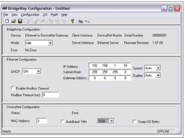
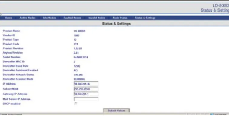
To integrate the Power Analyser into the GridVis evaluation and configuration software an Ethernet connection must be established to the device and the TCP/IP address defined!. •
If just one belt is bad, uneven load on belts, pulleys, bearings, and shafts can occur.. • Check pulley grooves to make sure they are not worn, damaged, or aligned
The Ministry reports to Parliament on all important matters relating to the Fund, such as the size of petroleum revenues and the Fund; the outlook for fiscal sustainability;
114 ff 119 Tempo di Minuetto Tempo di Minuetto Minuet... Andantino Andantino pp simile pp 8
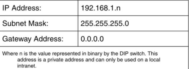
Then, edit the BOOTP configuration file (usually /etc/bootptab) and enter the name, network type (1 for Ethernet), Ethernet address and the IP address, subnet mask and gateway of
Then edit the BOOTP configuration file (usually /etc/bootptab) and enter the name, network type (1 for Ethernet), Ethernet address and the IP address, subnet mask and gateway of
Network Cards EtherNet/IP I/O EtherNet/IP I/O EtherNet/IP I/O EtherNet/IP I/O EtherNet/IP Drive EtherNet/IP I/O Switch 001 N-Tron 508TX-A with N-View EtherNet/IP I/O EtherNet/IP
