Department of Electrical and Computer
Engineering
LED DISPLAY PROJECT
By Betty Lise AndersonDescription
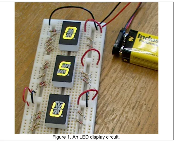
This document describes a hands-‐on project in which students design and build an LED display to light up their initials, Figure 1.
Figure 1. An LED display circuit.
First we will discuss how to read an electrical schematic, how to interpret an engineering data sheet, then how to design the circuit, and finally how to build it.
Reading electrical schematics
A schematic diagram is a drawing intended to indicate the electrical
connections of a circuit, as opposed describing what the circuit actually looks like, since its appearance is usually of no interest.
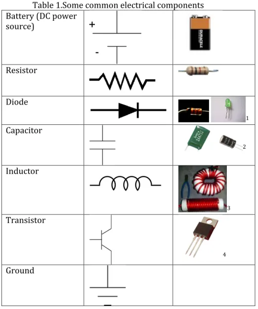
Table 1 shows the electrical symbols for a few components. In this project, we will use only the battery, diode, and resistor.
Table 1.Some common electrical components Battery (DC power source) Resistor Diode 1 Capacitor 2 Inductor 3 Transistor 4 Ground
Battery: You know what the battery is for!
1 commons.wikimedia.org/ wiki/File:Diodo_LED_verde.jpg 2 www.suntan.com.hk
3 http://www.powerlabs.org/railguncurrent.htm
Resistor: The purpose of a resistor is to…resist electricity! Why would we want to do that? To control how much current goes where. One reason is to protect other devices. We will use resistors to control how much current flows through our light-‐emitting diodes, both to control their brightness and to protect them.
Diode: A diode is a device that allows current to flow in only one direction. Figure 2 shows the direction of flow. Current can pass in the direction the “arrow” is pointing, that is from the anode to the cathode. The line at the point of the arrow reminds us that current cannot flow in that direction, from cathode to anode. In our case, we will be using light-‐emitting diodes. When current flows, they light up.
Figure 2. Direction of allowed current flow in a diode.
Figure 3 shows a simple diode circuit. There is a nine-‐volt battery, a diode and a resistor. In a circuit, current always flows from plus to minus. Therefore, in this circuit current flows out of the battery positive terminal, through the diode (this direction is allowed), through the resistor and into the negative battery terminal. This is actually the circuit we will build, but we will build it many times.
Figure 3. Simple diode circuit.
Figure 4 shows another circuit. In this case, no current flows at all, because the diode stops it.
Figure 4. Current does not flow in this case.
Reading the data sheet
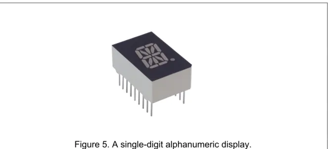
The display part we will use is a 16-‐segment alphanumeric display, Figure 6. With sixteen segments, you can make any letter in the English alphabet, any
numeral, and some punctuation.
Figure 5. A single-digit alphanumeric display.
When the engineer chooses the display, he or she reads the data sheet first. Figure 6 shows a typical first page. We see a list of “features,” for example saying that the letter will be a half inch high. The rest of the features are qualitative statements. For example, the segments are said to be uniform, or the brightness is said to be high, but it does not say how uniform or how bright. That is later, in the specifications, where numbers attached to those qualities. This front page is more or less advertising.
At the bottom, though, is a specific description of the part, saying it’s high-‐ efficiency red, with common anode and right-‐hand decimal point. You may actually use yellow or green parts; most of the data is the same.
Figure 7. First page of the data sheet for our part.
On the next page are the physical dimensions, Figure 8. The engineer will pass that sheet along to the person designing the circuit board. What’s important to us here is the spacing between the pins, since we will be using a solderless
breadboard whose holes should be on the same spacing. Fortunately, 0.1” and multiples thereof are industry standards so we have no problem here.
Also, the figure shows the labeling of the segments (A, B, C, etc).
NOTE: The individual segments are labeled with letters so you can identify which one to light up. For example, if you wanted to make an “E” you would
probably select segments A, B, H, G, U, F, E, and maybe P (your call). Sometimes someone new to this thinks that to make an “E” they just have to make a connection to the pin corresponding to “E.” That would only light one segment, in the lower right hand corner. It wouldn’t create the whole letter “E.”
Figure 8. Package dimensions.
Figure 9 givens the internal circuit diagram. We see that inside each package, there are 17 diodes. There is actually a separate diode chip underneath each
segment (and the decimal point). The numbers refer to the pin numbers on the package. Further, we see that all the anodes are connected to a common point. This common anode, pin 18, is the point through which all current, for all the diodes, enters the display.
Figure 9. Internal circuit diagram.
Figure 10 gives the pinout. It tells us not only which pin corresponds to which diode, but also how the pins are numbered. Looking from the top of the display, with the decimal point on the right, we find pin 1 in the upper right hand corner. The pin numbers increase down the left side and up the right side. This is standard for all integrated circuits.
Figure 10. Pinout.
Next come the “absolute maximum ratings,” Figure 11. For example, it says not to exceed 75 mW power dissipation per segment. If we do exceed that by a little, the part won’t explode (probably), but its lifetime will be reduced. This table also tells us not to exceed 25 mA per segment with continuous current. We will want to remember that later, when we do our design, since we will be using continuous current.
The “peak forward current per segment, 1/10 duty cycle, 0.1 ms pulse width)” specification is for more common situations, where there are many of these displays in a row, and the information being displayed is changing. In this case, the first digit is energized by applying a voltage to the common anode, and the
information for the first letter is sent by connecting the cathodes of only those segments needed for that digit. Then, the anode is turned off, and the anode of the next digit is turned out, and different cathode connections are made. The system cycles through the digits so fast you can’t see it. In this method, all the cathodes for segment “A” are connected together, but if cathode “A” is selected, only the display
whose anode is also connected will light up. This saves a lot of wires-‐ you need only 17 wires for the segments, plus one more wire for each digit. Since only one digit is on at a time, the current can be much higher without overheating the part because it has time to cool. If there are 10 letters, and only one is lit at a time, each letter is lit for 10% of the time, hence the 1/10 duty cycle. This system of reducing wires and cycling through the letters rapidly is called “multiplexing.” In our circuit, however, we will hard-‐wire the letters for a static display, so we’ll be using continuous current.
Figure 11. Absolute maximum ratings.
Another parameter in the absolute maximum ratings table is the reverse voltage per segment, set at 5V. This means that if the diode is connected up backward, we should not use more than 5V. Since we will be using a 9V battery, if we reverse the diode we will put 9V across it and definitely exceed that rating. Typically this particular specification (or “spec” for short) is conservative and the diode can survive 9V reverse, but it is not guaranteed.
Finally, we see the operating and storage temperature ranges. You will be building your circuit indoors, probably, but if you were an engineer designing, say, an instrument to measure snow in Antartica or temperature inside an oven, you’d want to pay close attention to the allowed range. Often the operating and storage temperatures are different. For example, a part might be able to survive being shipped from the factory on a very hot truck or through a blizzard, as long as it’s not operating.
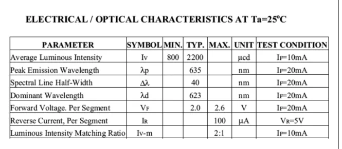
Now we get to the interesting part, the electro-‐optical characteristics, Figure 12.
Figure 12. Electro-optical characteristics.
The first is luminous intensity, which is helpful only if you know how bright a microcandela is. This comes with experience, and you will find out when you build it. Notice that the minimum is 800 µcd, but the typical value if 2200 µcd, and there is no maximum. What the vendor is telling us is that typically the part will be about 1200 µcd bright, but they guarantee it will not be any dimmer than 800 µcd at 10 mA of current at room temperature. If you try it out, and it is dimmer, you can return it. There is no maximum specification because brighter is better, so there is no reason to specify a limit.
The wavelength relates to the color. The high-‐efficiency red parts are 635 nm, which is orangey-‐red. There are yellow ones (585 nm) and green (565 nm) in this series as well. The spectral width refers to the purity of color and is not really of much interest for displays. All LEDs will be about the same in this regard. The
dominant wavelength is a human factor: the peak intensity is at 635 nm, but our eyes are more sensitive to lower wavelengths in this region, so we will perceive the display to be the color corresponding to 623 (more orange).
Now, the forward voltage per segment is of great interest, at 2 V. We will use this number later.
We will refrain from connecting the diode in reverse, so we don’t have to worry about the reverse current.
Finally, the intensity-‐matching ratio specifies that no segment within a display will be more than twice as bright as any other. This the specification on uniformity. Fortunately, the human eye cannot easily detect a change in intensity of a factor of two, believe it or not, so if this specification is met, it will look uniform to us.
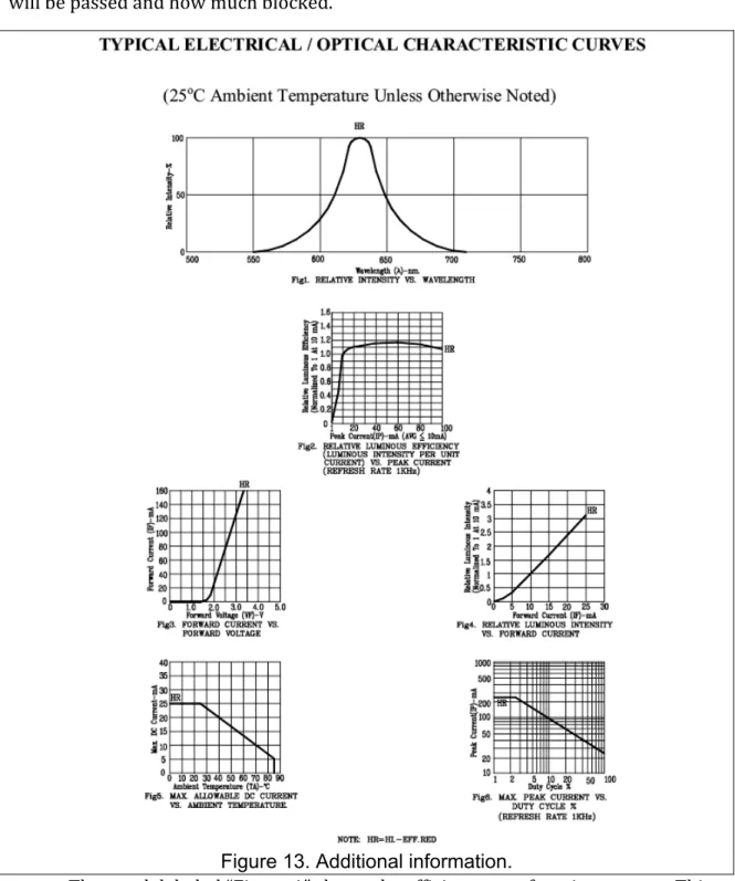
Finally, there is the “additional information” on the data sheet. We’ll go through this just to give a sense of what engineers do with this information. First up in Figure 13 is the optical spectrum, a plot of intensity versus wavelength. From the point of view at looking at the display, well, it will look orange. A reason that an engineer might be interested in the precise spectrum even though it’s just a display
is that we might want to put a filter in front of it to improve the contrast. When we look at the filter specifications, we will be able to tell how much of the display light will be passed and how much blocked.
Figure 13. Additional information.
The graph labeled “Figure 1” shows the efficiency as a function current. This plot tells us that one we get up past about 10 mA, the efficiency, light out vs. current in, is relatively constant. Note that the brightness is not constant, just the efficiency. This tells us we want to operate above 10 mA to get high efficiency, but after that it doesn’t matter.
The next graph shows current vs. voltage. We saw in the table of electro-‐ optical characteristics that the voltage across the LED at 20 mA was 2V. This graph goes into a little more detail—if we decide to operate at a high current, the voltage will be a little higher, and we can find how much from this graph. We also see that below 1.5V or so, almost no current flows.
The plot of relative luminous intensity vs. current, which is almost a straight line, tells us that if we increase the current, the brightness increases proportionally. So, to make it twice as bright we should double the current.
Of the last two plots, one warns us that if our device is going to be operated at a temperature above room temperature we are going to have to reduce the current, and tells us how much, and the other tells us that if the duty cycle gets to high (the device is on for a larger percentage of the time), we will also need to reduce the current. Notice that at 100% duty cycle (on continuously), the maximum current is 25 mA as noted earlier in the absolute maximum ratings. We are using 100% duty cycle.
Designing the circuit
We are now ready to do our design. Figure 14 shows the schematic diagram. There is a 9V battery, and three boxes, one for each display. Inside the box the 17 light-‐emitting diodes have all their anodes connected to a common point (the common anode), and there is a separate connection possible for each cathode. For each diode we want to light up, we will connect a resistor to the negative side of the battery (electrically the entire line across the bottom is equivalent to the negative battery). The resistor will control how much current flows. Where we do not connect a resistor, no current flows at all and that diode doesn’t light up.
Figure 14. Schematic of the circuit to build.
There is one more feature in Figure 14: a resistor labeled “100Ω (temp).” This is a safety resistor we will use just while we are building the circuit. It limits how much current can leave the battery since any current from the battery has to go through this resistor. With the safety resistor in place, if we accidently short
together two wires that shouldn’t touch, for example, allowing current to bypass one of the other resistors, we won’t draw so much current through a diode that we burn
it out. When we’re done, and everything is working correctly, we’ll remove that resistor and replace it with a wire.
Figure 14 shows the whole circuit, but really it’s just a multiple repeat of the circuit in Figure 15, except for the safety resistor. We know what the battery is (9V) and we know what the diode is, but we have to figure out the resistor. First, we recall that the voltage across the diode is about 2V, from the electro-‐optical
characteristics in Figure 12. There are 9V from the top of the circuit to the bottom on the left, so there must also be 9V from the top to the bottom on the right. Since we know tha approximately 2V is used up across the diode, theremust be
approximately 7V across the resistor.
Figure 15. Simplified circuit.
Now, you could argue (correctly) that the exact voltage across the diode will depend on the current, which we don’t know yet. We can make a good guess that it will be around 2V because we already found that the current should be above 10 mA and not greater than25 mA, and from the current-‐voltage characteristic, repeated in Figure 16, the voltage doesn’t change very much over that range. The value of “2 V” is an “engineering approximation.”
Figure 16. Current-voltage characteristic.
Choosing the current
Next, we have to decide on the current. As engineers, we will have to choose something. The engineering trade-‐offs are that if we choose a low current, the battery will last longer but the display will be dimmer. If we allow more current, the display will be brighter but the battery life will be shorter. Different engineers would choose different numbers.
Let’s pick 20 mA as an example (the actual choice is up to you, and should be between 10 mA, which so dim it’s hard to see, and 25 mA, which is the Absolute Maximum Rating).
Choosing the resistor
Next, we calculate the value of the resistor. From Figure 15, we know that there will be about 7 V across the resistor. The equation for the resistor, Ohm’s law, is
V =IR (1)
where V is the voltage (7V), I is the current (we picked 20 mA for this example, but it be anything between 10 mA and 25 mA), and we can calculate R=V/I=350 Ohms. Too bad there is no such thing as a 350 Ω resistor. Standard values in this
neighborhood are 270 Ω, 300Ω, 330Ω, 360Ω, 390Ω, and 430Ω. So, we will pick something close, either 330 Ω or 360 Ω, depending on what’s in the drawer. Checking the power
You can get resistors in different wattages, depending on the power consumption expected. The power dissipated in a component is
P=IV (2)
For us, the current is something close to 20 mA, and the voltage is around 7V, so the power dissipated in one resistor is 0.14 Watts. Standard sizes are ¼-‐ Watt and ½ Watt, so ¼ Watt resistors will do. They are slightly cheaper than half watt, and will dissipate the power we need.
Designing the letters
The displays we are using are 16-‐segment alphanumeric displays, Figure 17 (a). These can display numbers and letters, both upper case and lower case. Another popular alphanumeric display is th3 5×7 dot matrix, Figure 17b. The dot matrix makes nicer letters but can only be used in a multiplexed way, not direct
connections like we are using. One reason is that this part would require 36 pins to control all those diodes, and 37 resistors and wires. Figure 17 (c) shows a seven-‐ segment display. These are much cheaper than alphanumeric displays, and simpler, but can only display numbers and a handful of letters.
(a) (b) (c)
Figure 17. Three common display styles, a) 16-segment alphanumeric, b) 5×7 dot matrix alphanumeric, and c) seven-segment numeric.
Figure 18 shows a possible character set for the 16-‐segment display. For a few letters, there is more than one way to make them. A couple that are not obvious are “B” and “D.” Students often end up with “8” or “0” and may need to be coached a little on these.
Figure 18. One possible character set for 16-segment displays. Litronix.
Building the circuit
Parts list
For each circuit to be built, you will need the parts listed in Table 1. One possible suggested vendor is listed for each item; prices are circa March 2009.
Table 1.Parts list.
# Unit Description Vendor PN Unit Cost
1 Ea Solderless
breadboard Jameco.com 20601 $5.95
1 Ea 100Ω resistor, ½ Watt
Digikey OF101JE-‐ND $0.54 3 Ea 16-‐segment
display (OK to mix colors) Digikey. com 160-‐1106-‐ND (green) 160-‐1108-‐ND (red) 160-‐1107-‐ND (yellow) $2.70 30 to 40 Ea Carbon film resistor, ¼ Watt Suggestions: 270 Ω, 300Ω, 330Ω, 360Ω, 390Ω, 430Ω or 460Ω. Digikey OD361JE-‐ND (example, 360Ω) $0.42
1 Ea Battery snap Digikey BS6I-‐ND $0.30
1 Ea 9V battery Digikey P145-‐ND $2.31
Jumper wire Radio
Shack 276-173* $6.49
*This is a kit with assorted jumper wires. If you will be doing much breadboard work, it’s cheaper to buy spools of jumper wire, e.g. Digikey C2004B-‐ 100-‐ND, 100 foot spool, $16.24. Make sure the wire is solid, not stranded, and 22 AWG (that’s the wire gauge). Jumper wires can be cut and stripped ahead of time for a group.
Tools: Wire strippers, wire cutters, if you’re not buying the jumper wire kit. Not necessary but handy is an IC extraction tool, Digikey P/NK157-‐ND ($3.15) for removing displays from the breadboards without damaging the pins.
Preparing to build
• Decide what you want to display. Appendix 1 shows a convenient worksheet that has all the essential information in one place. At the top is a set of three digits, repeated here in Figure 18. It’s simplest to color in the segments you plan to use.
You may find it handy, once you’ve decided which segments to light up, to simply list the corresponding pin numbers from the pinout sheet next to the digit. For example, if you wanted to make an “M” you’d color in segments H, G, K, N, C, and D, and list pin numbers 5, 6, 4, 17, 16, and 13.
• Next, you should know how the breadboard is connected. Along the sides are four ”busses.” If you put a wire or a lead into a hole in one of the busses, and put another wire into another hole in the same buss, they will be connected (shown in green). Additionally, in each row of 5 holes, the holes are also connected The rows on the right are separated electrically from the holes on the left.
• Place the displays in the breadboard. Make sure all decimal points are down, and make sure the displays straddle the channel down the middle of the breadboard. Buss Row Decimal points
• Connect the battery snap. DO NOT CONNECT THE BATTERY. A look at the schematic tells you that you will need to make several connections to the one end of the safety resistor (temp), and many connections to the negative battery lead. That is what busses are good for. Connect the negative (black) battery lead to a bus. For the positive lead, the schematic shows that we will want to connect the positive battery lead (red) to the safety resistor, and then the other end of the safety resistor will need to go to a buss. The stripes on the safety resistor (100 Ω) are brown, black, brown. Ignore the gold stripe if there is one.
• Common Anode connection: Refer to the schematic again. You see that for each display, there is a connection from the positive buss (the one that the safety resistor is connected to) to the common anode of each device. From the pinout, you see that that is pin 18, and that pin 18 is in the upper right hand corner. To make this connection, connect a wire (red is conventional) from pin 18 to the positive buss. Do it for each of the three displays.
Connect black to a buss Red Connect red lead to a row you’re not using Connect safety (temp) resistor from red’s row to other buss BATTERY NOT CONNECTED! Black
• Extending the negative buss: from the schematic, you realize you will be connecting a lot of pins to the negative buss. Some of them will be on the right and some will be on the left. Create another negative buss by connecting the negative buss (the one with the black battery wire) to another buss on the other side.
• Connecting the cathode resistor: Choose the first segment you want to light up. Locate the appropriate pin. From the schematic, you see that you should connect a resistor from that pin to the negative buss. For this, use the value of cathode resistor you selected earlier (our example was 300 Ohms). Now you should have complete one circuit. Test it out-‐ try touching the battery to the snap and see if it lights up. If it does, disconnect the battery, and go ahead and connect the rest of the resistors, one for each segment you want to light up.
Connect to POSITIVE buss Pin 18
• Removing the safety resistor: Once the entire circuit is working correctly, you may remove the safety (temp) resistor. That will break the circuit, so you should move the positive battery lead directly to the positive buss. The circuit should light up, more brightly than before.
Debugging Tips:
Nothing lights up at all Check that Pin 18 (common anode) is connected to the positive buss
Check that the negative buss on the right hand side is connected to one on the left hand side
Only one display (digit) lights up Check that pin 18 (common anode) is Connect battery
to test- then disconnect battery before continuing
connected for the other displays The wrong segment lights up Check the pin number and the pin
location
One segment never lights up Check pin number
Swap another display to see if it is the display or the circuit
One segment much brighter than the
others May be shorted to ground. Make sure none of the resistors are touching together.
The breadboard doesn’t work It’s never the breadboard. Check your wiring.
Appendix 1. Summary sheet
! ! ! ! ! ! ! !
