EMC Elastic Cloud Storage (ECS)
Version 2.0ECS Documentation
302-001-980Published June, 2015
EMC believes the information in this publication is accurate as of its publication date. The information is subject to change without notice.
The information in this publication is provided as is. EMC Corporation makes no representations or warranties of any kind with respect to the information in this publication, and specifically disclaims implied warranties of merchantability or fitness for a particular purpose. Use, copying, and distribution of any EMC software described in this publication requires an applicable software license.
EMC², EMC, and the EMC logo are registered trademarks or trademarks of EMC Corporation in the United States and other countries. All other trademarks used herein are the property of their respective owners.
For the most up-to-date regulatory document for your product line, go to EMC Online Support (https://support.emc.com).
EMC Corporation
Hopkinton, Massachusetts 01748-9103
1-508-435-1000 In North America 1-866-464-7381 www.EMC.com
What's New 11
New features in ECS 2.0 13
New features... 14 Concepts 17 What is ECS? 19 Overview... 20 ECS platform... 20 Portal services... 20 Storage services ...20 Provisioning service... 21 Fabric service... 21 Infrastructure service... 21
Understanding data protection 23 Overview... 24
Storage service... 24
Object creates...24
Object reads...27
Erasure coding... 28
Recovery on disk and node failures... 29
Site fail over and recovery... 30
Install and Upgrade 31 Plan an installation 33 Overview... 34
Site preparation... 34
ECS installation readiness checklist... 34
Connecting ECS appliances in a single site ... 34
Multi-site requirements... 36
Configure and Manage 37 Getting started with the ECS Portal 39 Introduction... 40
Log in to the ECS Portal... 40
Change Password...41
Access to portal areas... 41
Ordering and searching tables in the portal... 44
Part 1 Chapter 1 Part 2 Chapter 2 Chapter 3 Part 3 Chapter 4 Part 4 Chapter 5
CONTENTS
Configure storage pools, VDCs, and replication groups 47
Configure storage pools, VDCs, and replication groups...48
Storage pools...48
Create storage pools... 49
Virtual data centers (VDCs)...49
Create a VDC for a single site...50
Add a VDC to a federation... 51
Fail over a site/Delete a VDC... 51
Replication groups... 52
Create replication groups... 52
Configure ConnectEMC... 53
Add users and assign roles 55 Introduction... 56
Understanding users and roles in ECS... 56
Users in ECS...56
User roles...57
Domain and local users...58
User scope: global or namespace...59
Working with the users at the ECS Portal... 60
Add a new object user...62
Add a domain user as an object user...63
Create a local management user or assign a domain user to a management role... 63
Create a namespace administrator...64
Working with the authentication providers at the ECS Portal...65
Add an authentication provider... 65
Authentication provider settings... 66
Considerations when adding authentication providers...70
Understanding the mapping of users into a namespace... 70
Map domain users into a namespace... 72
Configure a namepace for a tenant 75 Introduction... 76
Understanding tenants...76
Understanding namespace settings... 77
Working with namespaces at the ECS portal... 78
Create and configure a namespace...78
Obtain and upload a license file to the ECS Portal 81 Licensing...82
Obtain the EMC ECS license file...82
Manage a tenant 83 Introduction... 84
Quotas... 84
Retention periods and policies... 85
Lock buckets and users...86
Metering... 87 Audit buckets...88 Chapter 6 Chapter 7 Chapter 8 Chapter 9 Chapter 10
Fail over an ECS site 91
Fail over a site/Delete a VDC...92
Monitor 93 Monitor resources: hardware, network traffic, disk bandwidth, node and process health 95 About resource monitoring... 96
Using monitoring pages... 96
Monitor hardware...98
Monitor network traffic... 99
Monitor disk bandwidth... 100
Monitor node and process health...102
Monitor storage: metering and capacity 105 Introduction... 106
Using monitoring pages... 106
Monitor capacity... 108
Storage capacity data...108
Monitor metering data...110
Metering data... 111
Monitor service logs 113 Service logs...114
ECS service log locations...114
Monitor services: chunks, erasure coding, geo-replication, and recovery status 115 About service monitoring... 116
Using monitoring pages... 116
Monitor chunks... 118
Monitor erasure coding... 119
Monitor recovery status...120
Monitor geo-replication: rate and chunks... 121
Monitor geo-replication: Recovery Point Objective (RPO)... 122
Monitor geo-replication: failover... 123
Monitor geo replication: bootstrap processing... 124
Monitor events: audit portal, API, and CLI events and system alerts 127 About event monitoring...128
Filter events by date and sort the results by column... 128
Enable Data Access 129 Address ECS object storage and use the Base URL 131 Introduction... 132 Bucket addressing... 132 Chapter 11 Part 5 Chapter 12 Chapter 13 Chapter 14 Chapter 15 Chapter 16 Part 6 Chapter 17 CONTENTS
DNS Configuration...133
Base URL...133
Add a Base URL...135
Example of a Base URL...135
Create and configure buckets 137 Introduction... 138
Bucket concepts and attributes...138
Bucket ACLs... 141
Create a bucket using the ECS Portal... 142
Edit a bucket... 143
Set the bucket ACL permissions for a user... 144
Set the bucket ACL permissions for a pre-defined group...144
Create bucket using the object APIs...145
Create a bucket using the S3 API (with s3curl)...146
Bucket and key naming conventions... 148
S3 bucket and object naming in ECS... 149
OpenStack Swift container and object naming in ECS...149
Atmos bucket and object naming in ECS... 150
CAS pool and object naming in ECS...150
Obtain secret key to access object storage 151 Introduction... 152
Create a key for an object user... 152
Generate a secret key from the ECS Portal... 152
Create an S3 secret key using the ECS Management REST API... 152
Create an S3 secret key: self-service...153
Working with self-service keys...153
Configure support for CAS SDK applications with the ECS Portal 157 Setting up CAS support in ECS...158
CAS retention in ECS... 158
Set up namespace retention policies...160
Set up a bucket for CAS... 161
Set up a CAS object user... 161
Set up bucket ACLs for a user... 162
ECS REST APIs that support CAS users...165
Configure ECS HDFS 167 HDFS Overview 169 What is ECS HDFS?... 170
Configuring Hadoop to use ECS HDFS ... 171
ECS HDFS URI for file system access... 171
Hadoop authentication modes... 172
File system interaction... 174
Unsupported Hadoop applications...175
Configure HDFS in a non-secure Hadoop cluster 177 Configure ECS HDFS... 178 Chapter 18 Chapter 19 Chapter 20 Part 7 Chapter 21 Chapter 22
Plan the ECS HDFS and Hadoop integration...178
Obtain the ECS HDFS installation and support package...179
Create bucket for HDFS...179
Deploy the ECS HDFS JAR...180
Use a Cloudera Parcel to install Hadoop on a cluster ... 181
Edit Hadoop core-site.xml file... 181
Edit HBASE hbase-site.xml... 186
Configure HDFS in a secure Hadoop cluster 187 Configure secure Hadoop cluster to use ECS HDFS ...188
Plan the ECS HDFS and secure Hadoop cluster integration... 188
Obtain the ECS HDFS installation and support package...189
Create bucket for secure HDFS... 189
Deploy the ECS HDFS JAR in a secure cluster...190
Use a Cloudera Parcel to install Hadoop on a secure cluster...191
Configure ECS nodes with the ECS Service Principal... 192
Edit core-site.xml... 194
Guidance on Kerberos configuration... 198
ECS administration tool reference... 200
Troubleshooting an ECS HDFS configuration 203 Troubleshooting...204
Verify AD/LDAP is correctly configured with secure Hadoop cluster.204 Permission denied for AD user... 205
Restart services after hbase configuration...205
Pig test fails: unable to obtain Kerberos principal...205
Enable Kerberos client-side logging...205
Debug Kerberos on the KDC...206
Eliminate clock skew...206
ECS HDFS core site property reference 207 Hadoop core-site.xml properties for ECS HDFS... 208
Sample core-site.xml for simple authentication mode... 212
Access ECS Data 213 ECS Amazon S3 Object Service API support 215 Amazon S3 API...216
S3 API Supported and Unsupported Features... 216
API Extensions... 219
Authenticating with the S3 service... 224
Using SDKs to access the S3 service... 224
ECS OpenStack Swift Object Service API support 229 OpenStack Swift API...230
OpenStack Swift supported operations... 230
API Extensions... 231
OpenStack Version 1 authentication ... 236
OpenStack Version 2 authentication... 237
Authorization on Container... 239 Chapter 23 Chapter 24 Chapter 25 Part 8 Chapter 26 Chapter 27 CONTENTS
ECS EMC Atmos Object Service API support 241
EMC Atmos API Supported Features...242
Supported EMC Atmos REST API Calls...242
Unsupported EMC Atmos REST API Calls...243
Subtenant Support in EMC Atmos REST API Calls... 244
API Extensions... 245
Appending data to an object... 245
Use the REST API 247 Use the ECS Management REST API 249 Introduction... 250
Authenticate with the ECS Management REST API...250
Authenticate with AUTH-TOKEN ... 250
Authenticate with cookies... 252
Logout... 252
Whoami... 253
ECS Management REST API summary...253
Hardware Maintenance 257 ECS hardware 259 ECS Appliance hardware components... 260
ECS Appliance configurations and upgrade paths...263
U-Series single-phase AC power cabling ... 265
U-Series three-phase AC power cabling... 267
Switches... 271
Private switch: Arista 7048...272
Public switch: Arista 7150S-24... 272
Public switch: Arista 7124SX...273
Network cabling... 273
Nodes... 274
Server front views... 275
Server rear view... 276
Rack and node host names... 278
Disk drives... 279
Integrated disk drives...279
Disks and enclosures... 280
Disk drives in DAEs... 280
LCC... 284
Fan control module... 285
ICM... 285
DAE power supply... 287
U-Series SAS cabling...289
Replace an ECS storage disk in a U-Series Appliance 293 Drive replacement planning...294
Output for the cs_hal list disks command...294
Replace drives...295 Chapter 28 Part 9 Chapter 29 Part 10 Chapter 30 Chapter 31
Replace an ECS storage disk in third-party hardware 305
Drive replacement planning...306 Output for the cs_hal list disks command...306 Replace drives...307
Add a 60-disk upgrade to a U-Series ECS Appliance 313
60-disk upgrade planning... 314 cs_hal commands... 318 Perform a 60-disk upgrade... 319
ECS third-party rack requirements 325
ECS Third-Party Rack Requirements... 326
Chapter 32
Chapter 33
Chapter 34
CONTENTS
PART 1
What's New
Chapter 1, " New features in ECS 2.0 "
CHAPTER 1
New features in ECS 2.0
l New features... 14
New features
Describes the new features and additions for ECS 2.0. Controller
In previous releases, ECS used the ViPR controller to provide a number of services, such as authorization, authentication, licensing, and logging. These capabilities are now part of ECS and ViPR is no longer required.
In addition, the need for a virtual machine to install ECS has also been removed as the first node in an ECS appliance now acts as the installer for all nodes.
Portal
ECS was previously configured from the ViPR UI. With ECS 2.0, a new portal is provided that provides configuration, management, and monitoring capabilities to ECS and its tenants.
Monitoring and Diagnostics
ECS now provides comprehensive monitoring and diagnostics capabilities through the ECS Portal and the ECS API. The following features are supported:
l Metering
n Metering of namespace and bucket utilization
n Namespace and bucket time-based metering by capacity, bandwidth, and object
count.
l Capacity Utilization
n Monitoring of storage pool utilization. l Physical environment monitoring
n Monitoring of node and disk health
n Monitoring of node health - CPU, memory, and NIC usage n Monitoring of process health.
l Storage efficiency
n Monitoring of erasure coding job performance n Monitoring of chunk level usage
n Monitoring of recovery operations
n Monitoring of back end traffic for storage operations (erasure coding,
geo-reduction using XOR, recovery).
l Geo-replication monitoring n Replication monitoring n Failover monitoring n Bootstrap monitoring.
Geo Enhancements
The following enhancements have been made that improve the use of the ECS geo-replication mechanism:
l Geo Enhancement: Temporary Site Failover on page 15
l Geo Enhancement: Improved Recover Point Objective (RPO) on page 15 l Geo Enhancement: Multi-Site Access Performance Improvements through
Geo Enhancement: Temporary Site Failover
ECS 2.0 has automatic and sophisticated ways of handling temporary site failures and failbacks. With this new functionality, applications have access to data even when connectivity between federated VDCs is unavailable. There are some restrictions on some of the operations, such as creating new buckets while the sites are down. ECS will automatically resync the sites and reconcile the data when all the sites are operational and connected to each other again.
Geo Enhancement: Improved Recover Point Objective (RPO)
Prior to ECS 2.0, ECS object chunks were of a fixed size (128MB) and were sealed and replicated to a remote site only when the chunk was filled. Although this strategy was more efficient, it had the drawback that if an entire site or a rack went down, there could be many chunks with less than 128MB of data that had not been replicated. To overcome this, ECS 2.0 now starts the replication process as soon as a chunk starts receiving data. Geo Enhancement: Multi-Site Access Performance Improvements through Geo-caching Prior to ECS 2.0, where multiple VDCs were federated, any attempt to read an object had to go back to the VDC that owned the object. This meant that every time a user in another site accessed the data, it incurred a cost in terms of WAN bandwidth as well as slower performance caused by WAN latency.
ECS 2.0 solves this problem by caching objects at the secondary sites so that users can access the data locally without a WAN transfer.
Object Metering
Object metering enables key statistics to be retrieved for a tenant and for the buckets associated with a tenant. Metering data includes capacity, object count, objects created, objects deleted, and bandwidth (inbound as well as outbound) and can be retrieved for a specific point in time, or for a time range.
Retention Policies
Retention periods can be applied to object containers (object containers are referred to as buckets in Amazon S3, containers in OpenStack Swift, and subtenants in EMC Atmos) and objects to prevent critical data being modified within a specified period. In addition, ECS provides the ability to define policies that can be applied to objects so that the retention period is applied in accordance with the defined policy rather than a specific period.
Quota Management
Quota limits can be set on a bucket or namespace. This enables a tenant to define the maximum amount of storage that can be used for a namespace and enables tenants to create buckets that are quota limited. Hard and soft quotas can be applied independently or together, to record and event prior to imposing a hard limit.
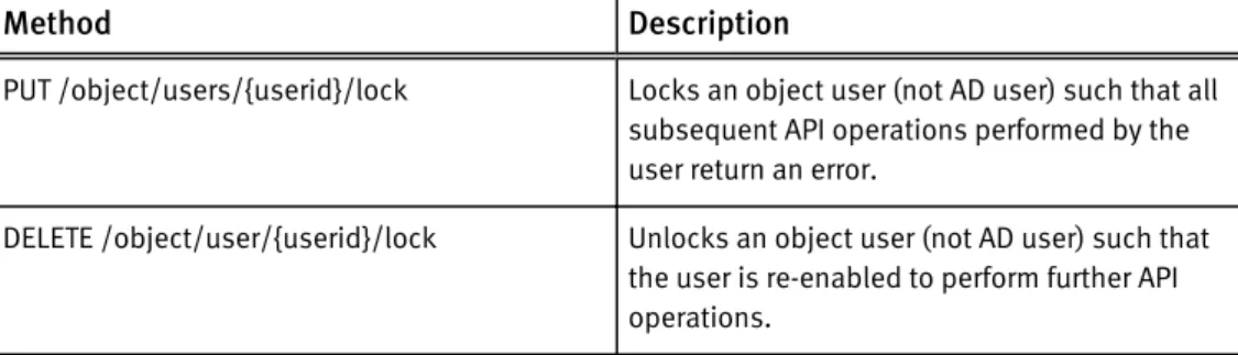
Bucket and User Locking
Locking can be applied at the bucket and user level, using the ECS Management REST API, as a means of preventing access.
Bucket Auditing
Bucket auditing is provided to enable create, update, and delete buckets operations and bucket access permission changes to be logged.
Enable Rack Level Awareness
Racks can be treated as separate fault domains enabling object store chunks to be distributed across these domains so that failure of a rack does not cause failure of the whole site.
New features in ECS 2.0
PART 2
Concepts
Chapter 2, "What is ECS?"
Chapter 3, "Understanding data protection"
CHAPTER 2
What is ECS?
l Overview... 20 l ECS platform... 20
Overview
ECS is a complete software-defined cloud storage platform that supports the storage, manipulation, and analysis of unstructured data on a massive scale on commodity hardware. ECS is specifically designed to support mobile, cloud, big data, and social networking applications. It can be deployed as a turnkey storage appliance or as a software product that can be installed on a set of qualified commodity servers and disks. The ECS scale-out, geo-distributed architecture is a cloud platform that provides:
l Lower cost than public clouds
l Unmatched combination of storage efficiency and data access
l Anywhere read/write access with strong consistency that simplifies application
development
l No single point of failure to increase availability and performance
l Universal accessibility that eliminates storage silos and inefficient ETL/data
movement processes
ECS platform
The ECS platform includes the following software layers and services: Figure 1 ECS platform services
Portal services
Portal services include interfaces for provisioning, managing, and monitoring storage resources. The interfaces are:
l GUI: A built-in browser-based graphical user interface called the portal Portal. l REST: A RESTful API that you can use to develop your own portal Portal.
l CLI: A command-line interface that enables you to perform the same tasks as the
browser-based interface.
Storage services
Storage services are provided by the unstructured storage engine (USE) which ensures data availability and protection against data corruption, hardware failures, and data
center disasters. It enables global namespace management across geographically dispersed data centers and geo-replication. The USE enables the following storage services:
l Object service: Provides the ability to store, access, and manipulate unstructured
data. The object service is compatible with existing Amazon S3, OpenStack Swift APIs, EMC CAS and EMC Atmos APIs.
l HDFS: Enables you to use your portal storage infrastructure as a Big Data repository
that you can run Hadoop analytic applications against (in-place).
Provisioning service
The provisioning service manages the provisioning of storage resources and user access. Specifically, it handles:
l User management: Keeps track of which users have rights to administer the system,
provision storage resources, and access objects via REST requests. portal supports both local and domain users.
l Authorization and authentication for all provisioning requests: Queries the
authentication domain to determine if users are authorized to perform management, provisioning, and access operations.
l Resource management: Enables authorized users to create storage pools, Virtual
Data Centers, and replication groups.
l Multi-tenancy: Manages the namespace that represents a tenant, and their
associated buckets and objects.
Fabric service
The fabric service is a distributed cluster manager that is responsible for:
l Cluster health: Aggregates node-specific hardware faults and reports on the overall
health of the cluster.
l Node health: Monitors the physical state of the nodes, and detects and reports faults. l Disk health: Monitors the health of the disks and file systems. It provides raw, fast,
lock-free read/write operations to the storage engine, exposes information about the individual disk drives and their status so the storage engine can place data across the disk drives according to the storage engine's built-in data protection algorithms.
l Software management: Provides command line tools for installing and running
services, and for installing and upgrading the fabric software on nodes in the cluster.
Infrastructure service
This layer provides the Linux OS running on the commodity nodes and it implements network interfaces and other hardware-related tools.
What is ECS?
CHAPTER 3
Understanding data protection
l Overview... 24 l Storage service...24 l Object creates... 24 l Object reads...27 l Erasure coding... 28 l Recovery on disk and node failures... 29 l Site fail over and recovery... 30
Overview
Learn about how ECS protects unstructured data against node, disk, and site failures through replication and erasure coding.
ECS ensures durability, reliability, and availability of objects by creating and distributing three copies of objects and their metadata across the set of nodes in the local site. After the three copies are successfully written, ECS erasure-codes the object copies to reduce storage overhead. It handles failure and recovery operations automatically with no additional backup software or devices required.
Storage service
The storage service layer handles data availability and protection against data corruption, hardware failures, and data center disasters.
The unstructured storage engine (USE) is part of the storage services layer. It is a distributed shared service that runs on each node, and it manages transactions and persists data to nodes. The USE enables global namespace management across geographically dispersed data centers through geo-replication.
The USE writes all object-related data (such as, user data, metadata, object location data) to logical containers of contiguous disk space known as chunks. Chunks are open and accepting writes, or closed and not accepting writes. After chunks are closed, the storage engine erasure-codes them. The storage engine writes to chunks in an append-only pattern so that existing data is never overwritten or modified. This strategy improves performance because locking and cache validation is not required for I/O operations. All nodes can process write requests for the same object simultaneously while writing to different chunks.
The storage engine tracks object location through an index that records object name, chunk id, and offset. Chunk location is separately tracked through an index that records chunk id and a set of disk locations. The chunk location index contains three disk location pointers before erasure coding, and multiple location pointers after erasure coding. The storage engine performs all of the storage operations (such as, erasure coding and object recovery) on chunks.
Object creates
Object creates: one VDC
The following figure shows how the storage engine writes object data when there is a single VDC. In this example, there is a single appliance deployed at the site, but the same principles apply when more appliances are deployed. The eight nodes are in a single storage pool within a single replication group.
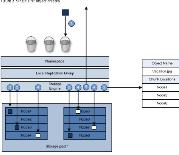
Figure 2 Single site: object creates
1. An application creates an object in a bucket.
2. The storage engine writes the object to one chunk. The disk locations corresponding to this chunk are on three different disks/nodes, so the writes go to three different disks/nodes in parallel. The storage engine can write the object to any of the nodes that belong to the bucket's replication group. The VDC where the object is created is the object's owner.
3. The storage engine records the disk locations of the chunk in the chunk location index, and the chunk id and offset in the object location index.
4. The storage engine writes the object location index to one chunk and the disk locations corresponding to the chunk to three different disks/nodes, so the writes go to three different disks/nodes in parallel. The index locations are chosen
independently from the object chunk locations.
5. After all of the disk locations are written successfully, the storage engine acknowledges the write to the application.
When object chunks are full, the storage engine erasure-codes them. It does not erasure code the object location index chunks.
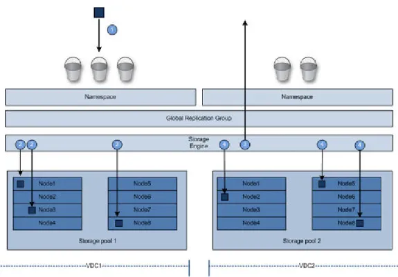
Object creates: federated VDCs (2 sites)
In a federated deployment of two VDCs, the storage engine writes object chunks to the local VDC and also to the remote VDC.
Understanding data protection
Figure 3 Two site: object creates
1. An application creates an object in a bucket.
2. The storage engine writes the object to one chunk at the site where it is ingested. The disk locations corresponding to this chunk are on three different disks/nodes, so the writes go to three different disks/nodes in parallel. The storage engine can write the object to any of the nodes that belong to the bucket's replication group. The storage engine records the disk locations of the chunk in the chunk location index, and the chunk id and offset in the object location index. The site where the object is originally ingested is the object's owner.
3. After all of the disk locations are written successfully, the storage engine acknowledges the write to the application.
4. The storage engine replicates the chunk to three nodes in the federated site. It records the chunk locations in the object location index (not shown in this diagram) also on three different nodes at the federated site.
When the chunks are full, the storage engine erasure-codes the object chunks. It does not erasure code the object location index chunks.
Three sites: object creates
Figure 4 Object creates: federated VDCs (3 or more sites)
1. An application creates an object in a bucket.
2. The storage engine writes the object to one chunk at the site where it is ingested. The disk locations corresponding to this chunk are on three different disks/nodes, so the writes go to three different disks/nodes in parallel. It can write the object to any of the nodes that belong to the bucket's replication group. The storage engine records the disk locations of the chunk in the chunk location index, and the chunk id and offset in the object location index (not shown in this diagram). The VDC where the write received is the object's owner, and it contains a readable copy of the object. 3. After all of the disk locations are written successfully, the storage engine
acknowledges the write to the application.
4. The storage engines replicates the chunks to nodes in another VDC within the
replication group. To improve storage efficiency, the storage engine XOR's the chunks with other chunks from other objects also stored on the node.
When the chunks are full, the storage engine erasure-codes the XOR'd chunks. When possible, it writes XOR chunks directly in erasure-coded format without going through the replication phase. It does not erasure code the object location index chunks.
Object updates
When an application fully updates an object, the storage engine writes a new object (following the principles described earlier). The storage engine then updates the object location index to point to the new location. Because the old location is no longer referenced by an index, the original object is available for garbage collection.
Object reads
Object reads: single VDC
In a single site deployment, when a client submits a read request, the storage engine uses the object location index to find which chunks are storing the object, it retrieves the chunks or erasure-coded fragments, reconstructs and returns the object to the client.
Understanding data protection
Object reads: federated VDCs (2 sites)
In a two-site federation, the storage engine reads the object chunk or erasure coded fragments from the nodes on the VDC where the application is connected. In a two-site federation, object chunks exist on both sites.
Object reads: federated VDCs (3 sites or more sites)
If the requesting application is connected to the VDC that owns the object, the storage engine reads the object chunk or erasure coded fragments from the nodes on the VDC. If the requesting application is not connected to the owning VDC, the storage engine retrieves the object chunk or erasure coded fragments from the VDC that owns the object, copies them to the VDC the application is connected to, and returns the object to the application. The storage engine keeps a copy of the object in its cache in case another request is made for the object. If another request is made, the storage engine compares the timestamp of the object in the cache with the timestamp of the object in the owning VDC. If they are the same, it returns the object to the application; if the timestamps are different, it retrieves and caches the object again.
Erasure coding
ECS uses erasure coding to provides better storage efficiency without compromising data protection.
The storage engine implements the Reed Solomon 12/4 erasure coding scheme in which an object is broken into 12 data fragments and 4 coding fragments. The resulting 16 fragments are dispersed across the nodes in the local site. The storage engine can reconstruct an object from any of the 12 fragments.
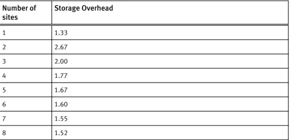
Table 1 Storage overhead when deploying multiple sites
Number of
sites Storage Overhead
1 1.33 2 2.67 3 2.00 4 1.77 5 1.67 6 1.60 7 1.55 8 1.52
ECS requires a minimum of four nodes running the object service in a single site. It tolerates failures based on the number of nodes.
Table 2 Node failure tolerance at a single site
Total nodes Node failure tolerance for writes
4 1
When an object is erasure coded, the original chunk data is present as a single copy that consists of 16 fragments dispersed throughout the cluster. When an object has been erasure-coded, ECS can read objects directly without any decoding or reconstruction. ECS only uses the code fragments for object reconstruction when there is hardware failure.
Recovery on disk and node failures
ECS continuously monitors the health of the nodes, their disks, and objects stored in the cluster. Since ECS disperses data protection responsibilities across the cluster, it is able to automatically re-protect at-risk objects when nodes or disks fail.
Disk health
ECS reports disk health as Good, Suspect, or Bad.
l Good — The disk’s partitions can be read from and written to.
l Suspect — The disk has not yet met the threshold to be considered bad.
l Bad — A certain threshold of declining hardware performance has been met. Once
met, no data can be read or written.
ECS writes only to disks in good health; it does not write to disks in suspect or bad health. ECS reads from good disks and from suspect disks. When two of an object’s chunks are located on suspect disks, ECS writes the chunks to other nodes. Node health
ECS reports node health as Good, Suspect, Degraded, or Bad.
l Good: The node is available and responding to I/O requests in a timely manner.
Internal health monitoring indicates that it is in good health.
l Suspect: The node is available, but is reporting internal health information such as a
fan failure (if there are multiple fans), a single power supply failure (if there are redundant power supplies). Or, the node is unreachable by the other nodes, but it is visible to BMC probes and is in an unknown state.
l Degraded: The node is available but is reporting bad or suspect disks.
l Bad: The node is reachable, but internal health monitoring indicates poor health. For
example, the node's fans are offline, the CPU temperature is too high, there are too many memory errors, and so on. Bad health can also be reported when the node is offline, and BMC probes indicate the health is not acceptable.
ECS writes only to nodes in good health; it does not write to nodes in suspect, degraded, or bad health. ECS reads from good and suspect nodes. When two of an object’s chunks are located on suspect nodes, ECS writes two new chunks of it to other nodes. When a node is reported as suspect or bad, all of the disks it manages are also considered suspect or bad.
Data recovery
When there is a failure of a node or drive in the site, the storage engine: 1. Identifies the chunks or EC fragments affected by the failure.
2. Writes copies of the affected chunks or EC fragments to good nodes and disks that do not currently have copies.
Understanding data protection
Site fail over and recovery
ECS provides protection against a site failure due to a disaster or other problem that causes a site to go offline or to be disconnected from the other sites in a geo-federated deployment.
Temporary site failure
Temporary site failures occur when network connectivity is interrupted between federated VDCs or when a VDC goes down temporarily. When a VDC goes down, the Replication Group page displays the status Temporarily unavailable for the VDC that is unreachable.
When buckets are configured with the Access During Outage property set to On, applications can read objects while connected to any site. When applications are connected to a site that is not the bucket's owner, the application must explicitly access the bucket to write to it or to view the contents. If an application modifies an object or bucket while connected to a VDC that is not the owner, the storage engine transfers ownership to the site where the change is initiated.
The following operations cannot be completed at any site in the geo-federation until the temporary failure is resolved regardless of the Access During Outage setting:
l Bucket: create or rename bucket, modify bucket properties, list buckets for a
namespace when the namespace owner site is not reachable
l Namespace: create l User: create
After the sites are reconnected, the storage engine starts a resync operation in the background. Use the portal's Monitor > Recovery Status to monitor the progress of the resync operation.
Permanent site fail over
If a disaster occurs at a site and the VDC cannot be brought back online, you must delete it.
PART 3
Install and Upgrade
Chapter 4, "Plan an installation"
CHAPTER 4
Plan an installation
l Overview... 34 l Site preparation... 34 l ECS installation readiness checklist... 34 l Connecting ECS appliances in a single site ... 34 l Multi-site requirements... 36
Overview
Learn about the physical environment, data center, and multi-site requirements as well as the private management network topologies.
Site preparation
Review the Site Preparation Guide to learn about the environmental requirements associated with the 40U-D cabinet used by the ECS Appliance.
ECS installation readiness checklist
Review this list for the infrastructure components required for a successful installation. An ECS appliance deployment consists of the following components:
l One or more racks.
n The rack must be up linked to the customer network for both data traffic and
remote management.
The rack and all nodes must be powered on.
The nodes must have valid IP addresses assigned by DHCP or configured statically .
l Infrastructure requirements: The data center environment must include the following
servers that are reachable from all nodes.
n DHCP server (if you are assigning IP addresses via DHCP) n DNS server (or forwarder)
n NTP server n SMTP server
SSH must be enabled on all nodes.
The following ports are opened and used by the installer:
l Docker registry: 5000 l Lifecycle agent: 9240 l Object: 9020-9025,9040,9091,9094-9098,8088,9898,1095,1096,1098,9100,9101,9111,3 218 l ZooKeeper: 9277,9278,9279
See the Security Guide for the list of ports that must be open.
Connecting ECS appliances in a single site
The ECS appliance management networks are connected together through the Nile Area Network. The NAN is created by connecting either port 51 or 52 to another turtle switch of another ECS appliance. Through these connections nodes from any segment can
The simplest topology to connect the ECS appliances together does not require extra switch hardware. All the turtle switches can be connected together a linear or daisy chain fashion.
Figure 5 Linear or daisy-chain topology
In this topology, if there is a loss of connectivity a split-brain can occur. Figure 6 Linear or daisy-chain split-brain
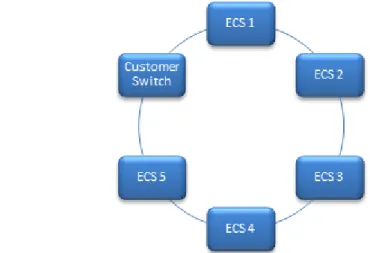
For a more reliable network, the ends of the daisy chain topology can be connected together to create a ring network. The ring topology is more stable because it would require two cable link breaks in the topology for a split-brain to occur. The primary drawback to the ring topology is that the RMM ports cannot be connected to the customer network unless an external customer or aggregation switch is added to ring.
Figure 7 Ring topology
The daisy-chain or ring topologies are not recommended for large installations. When there are four or more ECS appliances, an aggregation switch is recommended. The addition of an aggregation switch in a star topology can provide better fail over by reducing split-brain issues.
Plan an installation
Figure 8 Star topology
Multi-site requirements
When planning for a multi-site ECS installation, ensure these requirements are met:
l A minimum of two VDCs is required.
l Each VDC in the multi-site configuration requires IP connectivity to the other VDCs. n Network latency: Ensure a maximum latency of 1000 ms between sites.
n Free storage: If your disaster plan includes running for a period of time with one
site permanently failed (instead of promptly recovering the site), each site needs enough free storage across all sites to accommodate data rebalancing. Across all sites, the amount of free space left should be, in total:
free space across n sites =1.33*x/(n-1)/(n-2) where x is the total amount of user data across all n sites.
This amount of free space is not required if you add a new site soon after the fail over, and do not continue to operate with (N-1) sites indefinitely.
PART 4
Configure and Manage
Chapter 5, " Getting started with the ECS Portal "
Chapter 6, "Configure storage pools, VDCs, and replication groups" Chapter 7, " Add users and assign roles "
Chapter 8, " Configure a namepace for a tenant "
Chapter 9, "Obtain and upload a license file to the ECS Portal" Chapter 10, " Manage a tenant "
Chapter 11, "Fail over an ECS site"
CHAPTER 5
Getting started with the ECS Portal
l Introduction... 40 l Log in to the ECS Portal... 40 l Change Password...41 l Access to portal areas... 41 l Ordering and searching tables in the portal... 44
Introduction
The ECS Portal enables ECS to be configured, managed, and monitored.
In addition, the portal provides facilities for tenants to manage and monitor their namespace and to create and configure buckets within their namespace. The portal is primarily intended for access by ECS management users, system
administrators, and namespace/tenant administrators. Object storage users access ECS using the supported object protocols using clients that support those protocols. You can read more about ECS users and roles in Add users and assign roles on page 56.
The portal makes use of the public ECS Management REST API and it is possible to develop custom clients that use this API to perform operations.
Log in to the ECS Portal
You can log in to the ECS Portal from your browser by specifying the IP address of any node in the cluster.
Before you begin
l You can log in to the ECS Portal if your are assigned to the System Admin or
Namespace Admin ECS roles.
l A "root" user account, assigned to the System Admin role, is provided for initial
access.
You are automatically logged out after 15 minutes of inactivity. Procedure
1. Type the public IP address of the first node in the system, or the address of the load balancer that has been configured as the front-end to ECS, in the following form:
http:/<node1_public_ip>.
For example: http://198.51.100.244
2. Enter the username and password.
If you log in using the initial root credentials (root/ChangeMe), it is recommended that you change the password.
Your session ends when you close the browser, or log out. Logging out always closes the session. If you are unable to log in, contact your administrator.
Change Password
When you are logged in at the ECS Portal, you can change your password. Before you begin
System Admin and Namespace Admin users have access the Password page. If you are logged in as the root user, this account is not the same account as the root account used to provide command line access to a node. So, changing the password here will not change the password for the node root account.
Procedure
1. At the ECS Portal, select Settings > Password
2. Enter a new password in the Password field and enter it again as confirmation. 3. Click Save.
Access to portal areas
The portal provides a left navigation menu and a page area.
The System Admin can access all pages, a Namespace Admin can access a limited number of pages and perform only tenant-specific operations.
The followings sections detail the access provided for different management users.
Getting started with the ECS Portal
l System Admin on page 42 l Namespace Admin on page 43
System Admin
The following table lists the menu items that can be accessed and provides a link to documentation articles that provide more information on their use.
Area Menu Operations Supported
Monitor Metering View object metering for namespace or bucket. Monitor storage pool, node, and disk capacity. For more information, see: Monitor storage: metering and capacity on page 106.
Capacity Utilization
Events View audit events.
For more information, see: Monitor events: audit portal, API, and CLI events and system alerts on page 128.
Traffic Metrics Provides monitoring details, as follows:
l Monitor read and write bandwidth and latency. l Monitor storage node and disk status for each
storage pool.
l Monitor health of nodes and processes by memory
and CPU utilization.
l Monitor disk bandwidth usage.
For more information, see: Monitor resources: hardware, network traffic, disk bandwidth, node and process health on page 96
Hardware Health Node and Process Health Disk Bandwidth
Chunk Summary Provides monitoring details, as follows:
l Monitor chunks and chunks status. l Monitor erasure coding status. l Monitor recovery status. l Monitor geo-replication activity.
For more information, see: Monitor services: chunks, erasure coding, geo-replication, and recovery status on page 116.
Erasure Coding Recovery Status Geo Replication
Manage Storage Pools Enables the following operations:
l Add a storage pool and specify the nodes that it
comprises.
l Add a VDC and define its connection details. l Configure a replication group by adding storage
pools belonging to a VDC.
For more information, see: Configure storage pools, VDCs, and replication groups on page 48.
Virtual Data Center Replication Group
Authentication Add an authentication provider that can authenticate domain users.
See Add users and assign roles on page 56. Namespace Enables the following operations:
l Create a new namespace. l Set quota for namespace.
Area Menu Operations Supported
l Map object users into a namespace.
For more information, see: Configure a namepace for a tenant on page 76
Users Enables the following operations:
l Create object users for the namespace. l Edit object users.
l Create secret keys.
For more information, see: Add users and assign roles on page 56
Bucket Enables the following operations:
l Create bucket.
l Assign ACLs to bucket owner and object users.
For more information, see: Create and configure buckets on page 138
Settings Object Base URL Set the Base URL to determine which part of object address is the bucket and namespace.
For more information, see: Address ECS object storage and use the Base URL on page 132
Change Password Change own password.
For more information, see: Change Password on page 41
Connect EMC Configure sending of events to EMC. Licensing View license status and upload a license.
For more information, see: Obtain and upload a license file to the ECS Portal on page 82
Namespace Admin
The following table lists the menu items that can be accessed and provides a link to documentation articles that provide more information on their use.
Area Menu Operations Supported
Monitor Metering View object metering for namespace or bucket. For more information, see Monitor storage: metering and capacity on page 106
Manage Namespace Edit the namespace.
For more information, see Configure a namepace for a tenant on page 76
Users Enables the following operations:
l Create object users for the namespace. l Edit object users
Getting started with the ECS Portal
Area Menu Operations Supported
l Create secret keys for object users
For more information, see Add users and assign roles on page 56
Bucket Enables the following operations:
l Create bucket.
l Assign ACLs to bucket owner and object users.
For more information, see Create and configure buckets on page 138
Settings Change Password Change own password.
For more information, see Change Password on page 41
Ordering and searching tables in the portal
When a data set presented at the portal is large, and especially when it runs onto multiple pages, it is useful to be able to reorder a table and to search for information in the table.
An example of a page containing a table is shown below.
Reordering Table Columns
You can reorder the rows in a table based on the ordering of a selected column. A table column can be ordered by clicking on the table header.
Columns that contain textual data are sorted alphabetically. For example, if you select the Namespace field in the users table, that column will be ordered alphabetically and will
drive the ordering of rows. When you reenter the page, the default ordering will be applied. Similarly, refreshing the page will return the page to the default ordering. Using Search
The Search facility enables table rows to be filtered based on matching text strings. As you type text in the Search box, rows that contain strings that match the search string are displayed. The order in which the rows that match the search criteria are displayed depends on the ordering applied by the table column ordering (see Reordering Table Columns on page 44).
Refreshing a Page
A refresh control is provided on pages that contain table data. Using refresh will return the table to its default ordering.
Getting started with the ECS Portal
CHAPTER 6
Configure storage pools, VDCs, and replication
groups
l Configure storage pools, VDCs, and replication groups...48 l Storage pools...48 l Virtual data centers (VDCs)...49 l Replication groups... 52 l Configure ConnectEMC... 53
Configure storage pools, VDCs, and replication groups
Learn how to use the portal to create, modify, and delete storage pools, VDCs, and replication groups for single or federated deployments, and how configure ConnectEMC for the object service.
Users must be assigned to the System Admin role to perform these procedures.
Storage pools
Storage pools let you organize storage resources based on business requirements. For example, if you require physical separation of data, you can partition the storage into multiple different storage pools.
Use the Storage Pool Management page available from Manage > Storage Pools to view the details of existing storage pools, to create new storage pools, to modify existing storage pools, and to delete storage pools.
Figure 9 Storage Pool Management page
Table 3 Storage pool properties
Field Description
Name The name of the storage pool.
# Nodes The number of nodes assigned to the storage pool.
Status The current state of the storage pool and of the nodes. Storage pool states are:
l Ready: At least four nodes are installed and all nodes are in the ready
to use state.
l Not Ready: A node in the storage pool is not in the ready to use. l Partially Ready: There are less than four nodes and all nodes are in the
ready to use state.
Host Name The fully qualified host name assigned to the node. Node IP address The public IP address assigned to the node.
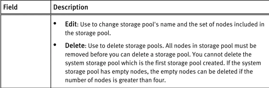
Rack ID The name assigned to the rack that contains the nodes. Actions Actions are:
Table 3 Storage pool properties (continued)
Field Description
l Edit: Use to change storage pool's name and the set of nodes included in
the storage pool.
l Delete: Use to delete storage pools. All nodes in storage pool must be
removed before you can delete a storage pool. You cannot delete the system storage pool which is the first storage pool created. If the system storage pool has empty nodes, the empty nodes can be deleted if the number of nodes is greater than four.
Create storage pools
Use this procedure to assign nodes to storage pools. Storage pools must contain a minimum of four nodes. The first storage pool that is created is known as the system storage pool because it stores system metadata. The system storage pool cannot be deleted.
Procedure
1. From the portal, select Manage > Storage Pools. 2. Click New Storage Pool.
3. Type the storage pool name. For example: StoragePool1.
4. Select the nodes to add to the storage pool from the Available Nodes list. a. To select nodes one-by-one, click the + icon next for each node.
b. To select all available nodes, click the + icon at the top of the Available Nodes list. c. To narrow the list of available nodes, type the node's public IP address or host
name in the search field.
5. When you have completed the node selection, click Save.
6. Wait 10 minutes after the storage pool is in the Ready state before you perform other configuration tasks. This allows the storage pool time to initialize.
If you do not wait long enough, you receive the following error message: Error 7000 (http: 500): An error occurred in the API Service. An error occurred in the API service.Cause: error
insertVdcInfo. Virtual Data Center creation failure may occur when Data Services has not completed initialization.
If you receive this error, wait a few more minutes before attempting any further configuration.
Virtual data centers (VDCs)
VDCs are logical constructs. They are the top-level resource that represents the collection of ECS infrastructure to manage as a unit.
Use the Virtual Data Center Management page available from Manage > Virtual Data Centers to view VDC details, to create a new VDC, to modify existing VDCs, to delete VDCs and to federate multiple VDCs for a multi-site deployment. The following example shows the Manage Virtual Data Center page for a multi-site, federated deployment. It is configured with three sites. The VDCs are named vdc1, vdc2, and vdc3.
Configure storage pools, VDCs, and replication groups
Figure 10 VDCManagement page
Table 4 VDC properties
Field Description
Name The VDC's name.
Endpoints The public IP addresses of the nodes in the storage pools that comprise the VDC. Status States are:
l Online
l Permanently Failed: The VDC was deleted.
Actions Actions are:
l Edit: Use to modify the VDC's name, the access key, and the public IP
addresses of the nodes in the VDC's storage pools.
l Delete: Use to delete a VDC. The delete operation triggers permanent fail over
of the VDC so you cannot add it back using the same name. You cannot delete a VDC that is part of a replication group until you first remove it from the
replication group. You cannot delete a VDC when you are logged in to the VDC you are trying to delete.
Create a VDC for a single site
Use this procedure when you are creating a VDC for a single site deployment, or when you are creating the first VDC in a multi-site federation.
Before you begin
One or more storage pools are available and in the Ready state. Procedure
1. From the ECS Portal, select Manage > Virtual Data Center. 2. Click New Virtual Data Center.
3. Type a name. For example: VDC1.
The name cannot have includes spaces or underscores. 4. Click Get VDC Access Key.
The VDC Access Key is used as a symmetric key for encrypting replication traffic between VDCs in a multi-site federation.
5. In the Endpoints text box, enter the public IP addresses of each node in the VDC's storage pools. Supply them as a comma-separated list.
Add a VDC to a federation
Use this procedure when you are adding a VDC (for example, VDC2) to an existing VDC (for example, VDC1) to create a federation.
Before you begin
Obtain the ECS Portal credentials for the root user, or for a user with system administrator credentials, to log in to both sites.
Ensure you have the list of public IP addresses for the nodes from the site you are adding (VDC2).
Ensure the site you are adding (VDC2) has a valid license uploaded and has at least one storage pool in the Ready state.
Procedure
1. Log in to the ECS Portal at the site you are adding (VDC2). The default credentials are root/ChangeMe.
2. Select Manage > Virtual Data Center. 3. Click Get VDC Access Key.
4. Select the access key, and copy it using Ctrl-C to save it in the buffer. 5. Log out of the ECS Portal at the site you are adding (VDC2).
6. Log in to the ECS Portal of the first VDC (VDC1). 7. Select Manage > Virtual Data Center.
8. Click New Virtual Data Center.
9. Enter the VDC's name. For example: VDC2.
10.Click into the Key field and paste (CTRL-V) the Key you copied from the site you are adding ( VDC2) from Steps 3 and 4 above.
11.Enter the public IP addresses of the site you are adding. Enter them as a comma-separated list.
12.Click Save.
Fail over a site/Delete a VDC
Use this procedure to delete a VDC. Deleting a VDC initiates site fail over when the VDC you are deleting is part of a multi-site federation.
If a disaster occurs, an entire VDC can become unrecoverable. ECS initially treats the unrecoverable VDC as a temporary site failure. If the failure is permanent, you must remove the VDC from the federation to initiate fail over processing which reconstructs and reprotects the objects stored on the failed VDC. The recovery tasks run as a
background process. Review the recovery process by using the Monitor > Geo Replication
> Failover Procesing. Procedure
1. Log in to one of the operational VDCs in the federation. 2. Go to Manage > Replication Group.
3. Click Edit for the replication group that contains the VDC to delete. 4. Click Delete in the row that contains the VDC and storage pool to remove.
Configure storage pools, VDCs, and replication groups
5. Click Save.
6. Go to Manage > VDC. The status for the permanently removed VDC changes to
Permanently failed.
7. Select Delete from the drop down in the row of the VDC to remove. 8. Click Save.
Replication groups
Replication groups are logical constructs that define where storage pool content is protected. Replication groups can be local or global. Local replication groups protect objects within the same VDC against disk or node failures. Global replication groups protect objects against disk, node, and site failures.
Use the Manage Replication Groups page to view replication group details, to create new replication groups, and to modify existing replication groups. You cannot delete
replication groups in this release. Figure 11 Manage Replication Groups page
Table 5 Replication Group properties
Field Description
Name The replication group name.
VDC The number of VDCs in the replication group and the names of the VDCs where the storage pools are located.
Storage Pool The names of the storage pools and their associated VDCs. Status States are:
l Online
l Temp Unavailable: Replication traffic to this VDC has failed. If all replication
traffic to the same VDC is in the Temp Unavailable state, further investigation about the cause of the failure is recommended.
Actions Edit: Use to modify the replication group name and the set of VDCs and storage pools in the replication group.
Create replication groups
Use this procedure to create replication groups.
To create global replication groups, choose storage pools from multiple VDCs. Procedure
1. From the ECS Portal, select Manage > Replication Group . 2. Click New Replication Group.
3. Type a name. For example: ReplicationGroup1.
4. Click Add VDC.
5. Select a Virtual Data Center and Storage Pool from the dropdown.
Repeat this step to add the VDCs and Storage pools required for object protection. 6. Click Save.
Configure ConnectEMC
Use this procedure to configure ConnectEMC for the object service. Procedure
1. From the portal, click Settings > ConnectEMC.
2. Select the transport type and whether the communications should encrypted. 3. If the transport type is FTPS, use the table below for assistance in completing the
configuration.
Option Description
Encryption Choose whether to encrypt the service data. Hostname Specify corpusfep3.emc.com.
Email Server Specify the SMTP server is used in the environment.
Email Addresses The email address to send ConnectEMC service notifications to. 4. If the transport type is SMTP, use the table below for assistance in completing the
configuration.
Option Description
Encryption Choose whether to encrypt the service data.
Authentication Choose an authenticate type for authenticating to the SMTP server or NONE. If authentication is required, you must also supply the UserName and Password for authenticating to the SMTP server. SMTP Server Enter the SMTP server hostname or IP address.
SMTP Port Enter the port for the SMTP server.
From Address The email address to display as the From address for ConnectEMC service notifications.
Email Addresses Additional email address to send ConnectEMC service notifications to.
5. Click Save.
For alerts to be sent out automatically, the system must be licensed, have ConnectEMC, storage pools, a VDC, and replication groups configured.
Configure storage pools, VDCs, and replication groups
CHAPTER 7
Add users and assign roles
l Introduction... 56 l Understanding users and roles in ECS... 56 l Working with the users at the ECS Portal... 60 l Working with the authentication providers at the ECS Portal...65 l Understanding the mapping of users into a namespace... 70
Introduction
This article describes the types of users supported by ECS and the roles to which they can be assigned.
It introduces the main concepts around ECS users and roles:
l Understanding users and roles in ECS on page 56 l Working with the users at the ECS Portal on page 60
and then describes how to add management users or object users:
l Add a new object user on page 62
l Add a domain user as an object user on page 63
l Create a local management user or assign a domain user to a management role on
page 63
l Create a namespace administrator on page 64
In addition, it shows you how you can set up an authentication provider and perform the mapping of domain users into a namespace:
l Add an authentication provider on page 65 l Map domain users into a namespace on page 72
Understanding users and roles in ECS
ECS defines different user types and roles to determine access to ECS management facilities and to the object store.
The main concepts relating to users and roles are described in the following topics:
l Users in ECS on page 56 l User roles on page 57
l Domain and local users on page 58
l User scope: global or namespace on page 59
Users in ECS
ECS requires two types of user: management users, who can perform administration of ECS, and object users, who access the object store to read and write objects and buckets using the supported data access protocols (S3, EMC Atmos, OpenStack Swift, and CAS). Management users can access the ECS Portal. Object users cannot access the ECS Portal but can access the object store using clients that support the ECS data access protocols. Management users and object users are stored in different tables and their credentials are different. Management users require a local username and password, or a link to a domain user account. Object users require a username and a secret key. Hence you can create a management user and an object user with the same name, but they are effectively different users as their credentials are different.
In addition, management and object user names can be unique across the ECS system or can be unique within a namespace. This is referred to as user scope and is described in:
User scope: global or namespace on page 59.
l Management Users on page 57 l Object users on page 57 l Root user on page 57
Management Users
Management users can perform the configuration and administration of the ECS system and of tenants configured in ECS.
Management users can be local users whose credentials are stored by ECS and are authenticated by ECS against the locally held credentials, or they can be domain users defined in Active Directory (AD) or Lightweight Directory Access Protocol (LDAP) and authenticated against users held in those systems. You can find out more about domain and local users in Domain and local users on page 58.
Management users are not replicated across geo-federated VDCs.
Object users
Object users are end-users of the ECS object store and access it through object clients using the ECS supported object protocols (S3, EMC Atmos, Openstack Swift, and CAS). Object users are defined by a username and a secret key that can be used to access the object store. Usernames can be local names or can be domain-style user names that include a "@" in their name.
A management user can create an object user account and can assign a secret key to the object user account when the account is created or at any time thereafter. When created by a management user, the object users secret key is distributed by email or other means.
For domain users, a secret key can be obtained by the object user using the ECS self-service capability, using a client that talks to the ECS REST API (object users do not have access to the ECS portal). You can read more about domain users in: Domain and local users on page 58, and you can refer to Obtain secret key to access object storage on page 152 for information on creating a secret key.
However, object users use ECS-held credentials, and no link to an AD account is stored, so ECS does not check whether the name exists in AD or is mapped into the namespace. Object users are global resources, so an object user created at a VDC can be given privileges to read and write buckets, and objects, within the namespace to which they are assigned, from any VDC.
Root user
The root user is available at system initialization and is pre-assigned to the System Admin role.
The root user should only be used for initial access to the system. On initial access, the root user password should be changed at the Settings > Password page and one or more new System Admin accounts should be created.
From an audit perspective, it is important to know which user carried out changes to the system, so root should not be used, and each System Admin user should have their own account.
User roles
ECS defines roles to determine the operations that a user account can perform at the ECS Portal or when accessing ECS using the ECS Management REST API. Management users
Add users and assign roles
can be assigned to administration roles in ECS and can be either local users or domain users.
If a management user who is a domain users is to be assigned to the Namespace Admin role, the user must be mapped into the namespace,
The following management roles are defined:
l System Admin on page 58 l Namespace Admin on page 58
System Admin
The System Admin role can configure ECS and specify the storage used for the object store, how the store is replicated, how tenant access to the object store is configured, and which users have permissions on an assigned namespace.
The System Admin can also configure namespaces and perform namespace
administration, or can assign a user who belongs to the namespace as the Namespace Admin.
The System Admin has access to the ECS Portal and system administration operations can also be performed from programmatic clients using the ECS Management REST API. Because management users are not replicated across site, a System Admin must be created at each VDC that requires one.
If a management user who is a domain users is to be assigned to the Namespace Admin role, the user must be mapped into the namespace,
Namespace Admin
The Namespace Admin is a management user who can access the ECS Portal to configure namespace settings, such as quotas and retention periods, and can map domain users into the namespace and assign local users as object users for the namespace.
Namespace Admin operations can also be performed using the ECS Management REST API.
A Namespace Admin can only be the administrator of a single namespace.
Because authentication providers and namespaces are replicated across sites (they are ECS global resources), a domain user who is a Namespace Admin can log in at any site and perform namespace administration from that site.
Local management accounts are not replicated across sites, so a local user who is a Namespace Admin can only log in at the VDC at which the management user account was created. If you want the same username to exist at another VDC, the user must be created at the other VDC. As they are different accounts, changes to a same-named account at one VDC, such as a password change, will not be propagated to the account with the same name at the other VDC.
Domain and local users
ECS provides support for local and domain users.
Local users are user accounts whose credentials are stored by ECS. Both management users and object users can be defined locally to ECS. In the case of object users, the credentials are global resources and are available at all ECS VDCs.
Local users make it very simple to start using ECS, however, the use of AD/LDAP enables an existing user database to be leveraged and allows a large number of users to be given access to the object store without having to create accounts for them.
Domain users are users defined in an Active Directory AD/LDAP database and ECS must talk to the AD or LDAP server to authenticate user login request. ECS uses a construct