e-ISSN: 2250-3021, p-ISSN: 2278-8719 Vol. 3, Issue 2 (Feb. 2013), ||V3|| PP 29-33
Calculation of Interharmonics of Time Varying Load Using
Labview
A.K. Baliar Singh, G.C. Martha, N.R. Samal, I. Shial
Department of Electical Engineering, OEC, BBSR
Abstract: Using adaptive window width an accurate, simple, and practical numerical method for exact calculation of harmonics/interharmonics is explained. Completely eliminate the unacceptable spectral leakage errors in the frequency domain caused by truncation of the time-domain signal. Various case studies are simulated by LabVIEW. Using adaptive window width the numerical method is for exact calculation of harmonics/interharmonics component. This method adaptively adjusts the window width based on correlation calculation. Thus eliminating the unwanted spectral leakage caused by truncation. The iterative algorithm does not require any knowledge about the system frequency and the interharmonic constituents. The only parameter needed is the signal sequence obtained by sampling the analog signal at equidistant sampling interval.
Chapter 1
I. INTRODUCTION
1.1 Introduction
The integral multiple of the fundamental supply frequency are harmonics in voltages or currents wave form. Non-integral multiple of the fundamental supply frequencies are interharmonics in the voltages or currents wave form. Interharmonics always present in the power system due to present of power electronic equipment. The widespread use of power electronic devices in power systems results in increase interharmonics magnitude.
The exact spectrum of a waveform provides a clear understanding of the causes and effects of waveform distortion. So in modern power system harmonics and interharmonics component are important for accurate analysis and measurement. In this case, the basic tool is discrete Fourier transform (DFT). DFT approximates the continuous Fourier transform of the time-domain signal. This approximation is a function of the waveform being analysed and the signal sequence covered by a window width. If the window width of DFT is not properly chosen there will be spectral leakage [1], [2].
In order to limit leakage effects, the classical Hanning window is used instead of the rectangular window. [3]. Also windowing functions other than the rectangular window can reduce the spectral leakage to some extent. It is well known that the best solution of avoiding spectrum leakage is to select a window width that covers a period or an integer multiple of period of a signal. This is considered to be most challenging because the interharmonic frequencies are unpredictable and the system frequency may also vary.
Here show an adaptive algorithm to determine the window width through an iterative procedure based on correlation calculation. Given a signal sequence it is obtained by sampling a periodic time-domain waveform at equidistant interval. These eliminate the unwanted frequency leakage caused by truncation. Various case studies show that the proposed adaptive approach completely eliminates or significantly reduces the spectral leakage errors of DFT in the frequency domain.
The harmonic and interharmonic analysis recommendations contained in the latest International Electro technical Commission (IEC) standards on power quality are considered. Sensitivity analyses on simple case studies together with experimental results show the sensitivity of the signal processing recommended by the IEC to synchronization errors and the usefulness of the improvements proposed.
1.2 Definitions
In spectral components in a quasi-steady state over a defined range of frequencies are used to define the Harmonics and interharmonics of the waveform. Table 1 provides mathematical definitions of Harmonics and interharmonics. “Subharmonic” does not have any official definition. It is an interharmonic of a frequency less than the fundamental frequency.
IEC 61000-2-1 standard defines interharmonics as follows:
Table 1.1 Spectral component of waveforms (of frequency f) Harmonic f = nf1 where n is an integer greater than zero DC component f = nf1 for n = 0
Interharmonic f ≠ nf1 where n is an integer greater than zero Subharmonic f > 0 Hz and f < f1
f1 = voltage fundamental frequency (basic harmonic)
1.3 LabVIEW
Graphical programming of LabVIEW (Laboratory Virtual instrument engineering workbench) has been utilized to simulate and measure different harmonics, interharmonics, noise and impulsive transients in the sinusoidal voltage waveforms. Results have been displayed on instrument like front panels on a computer screen, called virtual instruments. With virtual instrumentation, engineers and scientists can reduce development time, design higher quality products, lower their design costs, and keep close watch on waveforms. This helps in efficient use of electric power, and system reliability is also improved at the same time.
LabVIEW is a graphical programming language. It uses icons instead of lines of text to create applications. Instructions determine program execution in text-based programming languages. Where LabVIEW uses dataflow programming and the flow of data determines execution. By using a set of tools and objects build a user interface in LabVIEW. The user interface is known as the front panel. The block diagram contains this code. LabVIEW is integrated fully for communication with hardware such as GPIB, VXI, PXI, RS-232, RS-485, and plug-in DAQ devices. LabVIEW also has built-in features for connecting application to the Web using the LabVIEW Web Server and software standards such as TCP/IP networking and ActiveX. LabVIEW is a 32-bit compiler.
1.4Literature Review
R. W. Ramirez [1] proposed DFT approximates the continuous Fourier transform of the time-domain signal. This approximation is a function of the waveform being analysed and the signal sequence covered by a window width. If the window width of DFT is not properly chosen there will be spectral leakage. E. O. Brigham [2] discussed the exact spectrum of a waveform provides a clear understanding of the causes and effects of waveform distortion. So in modern power system harmonics and interharmonics component are important for accurate analysis and measurement. In this case, the basic tool is discrete Fourier transform (DFT).A. Testa, D. Gallo, and R. Langella [3] presented in order to limit leakage effects, the classical Hanning window is used instead of the rectangular window.
Electromagnetic compatibility (EMC) [4]-[6], analyzed that interharmonics are generated by periodical time varying loads, by circuits characterized by multiple switching functions, etc. The effects, such as the malfunctioning of remote-control systems, erroneous firing of thyristor apparatus, display or monitor image fluctuations or lighting system flicker, may be very remarkable. This is determining a trend of standards in fixing limits for interharmonics lower than limits for harmonics.
Arrillaga J, Watson N R, Chen S [7] proposed for such loads, the frequency at which the load varies will determine the frequencies of interharmonics.
Chapter 2
II. SOURCES OF INTERHARMONICS
2.1 Sources
There are some types of load for the generation of interharmonics. The generation of components in the sidebands of the supply voltage, frequency and its harmonics cause of changes in their magnitudes and/or phase angles. Due to rapid changes of current in equipment, or fluctuations in the voltage source as a result of interharmonics generate. Loads operating in a transient state continuously disturbances are generated. Largely these disturbances are random nature, depending on the load changes.
Basic sources of interharmonics are:
1. Arcing loads 2. Electric motors
3. Double Conversion Systems 4. Cycloconverters
5. Time-Varying Loads 6. Wind Turbines 7. Unexpected Sources
When transformers are subject to saturation and during switching processes interharmonics are generated.
2.2 Effects of the presence of interharmonics
Interharmonic currents cause interharmonic distortion of the voltage depending on magnitudes of the current components and the supply system impedance at that frequency. The greater the range of the current components’ frequencies, the greater is the risk of the occurrence of unwanted resonant phenomena, which can increase the voltage distortion and cause overloading or disturbances in the operation of customers’ equipment and installations. Among the most common, direct, effects of interharmonics are:
1) Thermal effects
2) Low-frequency oscillations in mechanical systems
3) Disturbances in fluorescent lamps and electronic equipment operation. In practice, the operation of any equipment that is synchronised with respect to the supply voltage zero-crossing or crest voltage can be disturbed (Figure 2.1)
Figure 2.1 - Multiple zero-crossing of the voltagewaveform as a result of distortion
4) Interference with control and protection signals in power supply lines. This is now the main harmful effect of interharmonics
5) Overloading passive parallel filters for high order harmonics 6) Telecommunication interference
7) Acoustic disturbance
8) Saturation of current transformers. The most common effects of the presence of interharmonics are variations in rms voltage magnitude and flicker.
Chapter 3
III. RESULTS AND DISCUSSIONS
3.1 Case Studies
In this section we take different case of interharmonics source parameter by LabVIEW simulation to assess the performance of the proposed algorithm.
3.2 AC-DC Rectifier
Interharmonics contain in ac/dc rectifier and a dc/ac inverter. The coupled reactor or capacitor in rectifier and inverter are called dc link. If the reactor or the capacitor has infinite value, there will be no ripples on the dc side. The ideal rectifier will only generate characteristic harmonics of
1
(
1)
hf
p n
f
2 0 r
f
np f
Where
p
2 pulse number of the inverter0
f
is the output frequency n is an integer number.Here assume f0 is set as 30,
p
2
6
,p
1
12
. If the inverter output frequency has a minor deviationfrom 30 Hz, for example, 29.4 Hz, the DC link reactor will has ripple frequency of
6 29.6 176
Hz. This ripple will beat with fundamental and consequently 50+176=236 Hz and 176-50=116 Hz interharmonics will be generated.Fig. 3.1 shows the fundamental supply to the arc load at 50 Hz. The time domain of fundamental wave shape is shown in Fig. 3.2 and the frequency spectrum is 50 Hz shown in Fig. 3.3.
Fig. 3.1 Sinusoidal signal applied to arc furnace.
Fig 3.2 Time domain of fundamental sin wave shape applied to arc furnace.
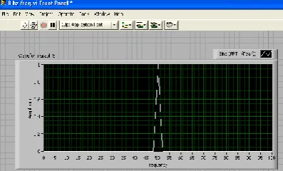
Fig. 3.3 Magnitude spectrum of Sinusoidal signal applied to arc furnace.
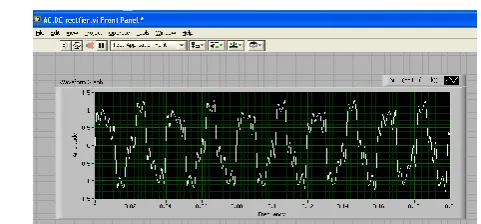
Fig 3.4 shows the Wave forms of AC-DC rectifier and DC-AC inverter the rectifier and inverter are coupled through a reactor or capacitor.
Fig. 3.4 Wave forms of AC-DC rectifier and DC-AC inverter the rectifier and inverter are coupled through a reactor or capacitor.
Chapter 4
IV. CONCLUSIONS
Interharmonic theory and modelling have been presented in this chapter. Starting from the basic definitions and concepts, attention has been taken for interharmonic sources. Then, give the particular attention to the problem of the frequency resolution and of the computational burden. Finally, modellings of different kind of interharmonic sources are done.Using adaptive window width the numerical method is for exact calculation of harmonics/interharmonics component. This method adaptively adjusts the window width based on correlation calculation. So eliminating the unwanted spectral leakage caused by truncation. The iterative algorithm does not require any knowledge about the system frequency and the interharmonic constituents. The only parameter needed is the signal sequence obtained by sampling the analog signal at equidistant sampling interval. Various case studies are done using LabVIEW programming simulation data, show that the proposed algorithm provides an ideal numerical solution to the problem of spectral leakage encountered in power system harmonics and interharmonics analysis and detection.
REFERENCES
[1] R. W. Ramirez, The FFT: Fundamentals and Concepts. Englewood Cliffs, NJ: Prentice-Hall, 1985. [2] E. O. Brigham, The Fast Fourier Transform and its Applications. Englewood Cliffs, NJ: Prentice-Hall,
1988.
[3] A. Testa, D. Gallo, and R. Langella, “On the processing of harmonics and interharmonics: Using Hanning window in standard framework,” IEEE Trans. Power Del., vol. 19, no. 1, pp. 28–34, Jan. 2004.
[4] Interharmonic Task Force Working Document – IH0101 20001, IEEE
[5] IEC 61000-2-1: 1990 - Electromagnetic compatibility (EMC) Part 2: Environment – Section 1: Description of the environment – Electromagnetic environment for low-frequency conducted disturbances and signalling in public power supply systems
[6] IEC 61000-2-2: 2002 - Electromagnetic compatibility (EMC) Part 2: Environment – Section 2: Compatibility levels for low-frequency conducted disturbances and signalling in public low-voltage power supply systems. (also materials used in preparation of the standard, obtained from the authors) [7] Arrillaga J, Watson N R, Chen S: Power system quality assessment, Wiley, 2000
[8] Gunther E W: Interharmonics in power systems, UIEPQ-9727
[9] IEC 61000-4-7: 2002 Electromagnetic compatibility (EMC) Part 4: Testing and measurement techniques Section 7: General guide on harmonics and interharmonics measurements and instrumentation for power supply systems and equipment connected thereto
[10] IEC 61000-4-13: 2002 Electromagnetic compatibility (EMC) Part 4: Testing and measurement techniques Section 13: Harmonics and interharmonics including mains signalling at ac power port, low frequency immunity tests (also materials used in preparation of the standard, obtained from the authors) [11] Kloss A: Oberschwingungen, vde Verlag, ISBN 3-8007-1541-4
[12] Materials used in preparation of standard IEC 61000-2-4 (obtained from the authors) [13] J. Arrillaga and N. R. Watson, Power System Harmonics, 2nd. New York: Wiley, 2004.
[14] C. Vilar, J. Usaola, and H. Amaris, “Frequency domain approach to wind turbines for flicker analysis,” IEEE Trans. Energy Convers., vol.18, no. 2, pp. 335–341, Jun. 2003.
[15] “Interharmonic in power system,” IEEE interharmonic task force, to be published.
[16] R. C. Dugan, M. F. McGranaghan, S. Santoso, and H. W. Beaty, Electrical Power Systems Quality. New York: McGraw-Hill, 2003.