Selecting the Right Cable System
for Your Environment
July 2010
White Paper
Abstract:
Cables are often the last component considered during system designs. In many situations, cables are really the system’s lifeline — if a cable goes down, the entire system can stop. For example, if the cable system used for data transmission in a spacecraft fails, the communication between the craft and mission control could be lost. Cable reliability is based on both durability and signal integrity, and the ideal cable system should be engineered to last the life of the product in any environment.
Selecting the Right Cable System
for Your Environment
Paul Warren, Lead Design Engineer
Contents
Page Number Topic
2 Introduction
2 Identifying Constraints
4 Designing the Cable System
4 Choosing the Right Material
8 Verifying the Cable Design
9 Understanding Total Cost of Ownership
Selecting the Right Cable System
for Your Environment
Cables are often the last component considered during system designs. In many situations, cables are really the system’s lifeline — if a cable goes down, the entire system can stop. For example, if the cable system used for data transmission in a spacecraft fails, the communication between the craft and mission control could be lost. Cable reliability is based on both durability and signal integrity, and the ideal cable system should be engineered to last the life of the product in any environment.
The environments in which cable systems are being used today are becoming more challenging. For example, cables are being exposed to such things as extreme temperatures, chemicals, abrasion, and extensive fl exing. A harsh environment can be considered any combination of conditions unique to an application that will compromise the reliability and performance of the cable system. Additional factors can include the need for smaller, lighter packaging for cable systems that last longer and cost less. Regardless of the application for which you are designing an electrical system, it is essential to identify all of the potential factors that can affect the electrical performance of the cable system. These variables have a direct impact on the materials used for cable insulation and jacketing as well as the construction of the cable. Using a systematic approach will help ensure that you select the best cable for your application — an approach that includes the following:
• List the constraints that will affect performance, including electrical, mechanical, environmental, and application-specifi c factors.
• Share this list with your cable manufacturers so they can select the best materials and construction; through testing and data analysis, the manufacturer should demonstrate that the cable will, in fact, perform in your environment.
• Understand your total cost of ownership. How much does it matter? What is the cost of a failure?
Many of today’s applications have environmental infl uences that require unique materials and mechanical properties to ensure reliable cable performance. First you need to consider the electrical, mechanical, and environmental stress that the cable will encounter in your application. In addition, most applications have unique issues that can stress a cable system, such as the need for extreme temperatures in a geophysical applica-tion or vibraapplica-tion in aerospace applicaapplica-tions.
Electrical performance is probably the fi rst and foremost consideration in a cable system, and many factors can potentially compromise signal integrity, such as • electromagnetic interference (EMI) from both sources inside the cable and
external sources;
• crosstalk, which results from unwanted coupling of signals between two transmission circuits;
Identifying Constraints Introduction
• attenuation, which ultimately determines the maximum length of a signal cable; and
• conductor resistance, which affects voltage drop over a power line. Electrical performance is typically very reliable when there are not other environmental factors; however, when you add mechanical, environmental, or application-specifi c stress, it can become very diffi cult to maintain reliable electrical performance.
Mechanical stress occurs when cable systems are exposed to movement, often in tight spaces at high speeds, such as in hand-held devices or
automation and aerospace applications. Movement includes random, rolling, and torsion types of motion. These types of fl exing create kinetic energy in the cable, which can cause severe damage if not properly managed. When cables move, they rub against each other, the cable chain, or other hardware in the system, generating friction that can result in jacket abrasion. One of the biggest causes of mechanical stress on cables is when the cable is part of equipment handled by a person. An operator can kink, pinch, or crush a cable by stepping on it or rolling equipment over it. Therefore, tensile strength is essential in overcoming mechanical stress. Also, when cables move in a harsh environment, they can come into contact with sharp surfaces that can cut cables or expose them to severe abrasion. When the complexities of compensating for extreme acceleration and vibration are added, mechanical stress can signifi cantly compromise signal integrity and cause premature failure of a cable.
Environmental stress results from the physical area in which the cables are used and exposed. Extreme temperatures affect cable materials, with low temperatures making them brittle and high temperatures causing them to become very soft. Like extreme temperatures, extreme pressures can have a signifi cant impact on cables. Vacuum, which is just a very low level of pressure, leaches oils and additives out of a cable, contaminating the work surface such as in a clean manufacturing process for semiconductor chips. On the other hand, hydrostatic pressure, like that found in geophysical exploration, causes gas or liquids to permeate insulation or cable jackets. Gases and liquids such as cleaning fl uids, fuel, lubricants, chemicals, and steam destroy some cable materials. Radiation can damage both insulation and jacket materials, depending on the type and dosage level. Friction, which is caused by cable movement, can compromise cable jackets by causing particulation, while contaminants such as mud, chemicals, or metal chips, can damage the cable jacket. Environmental stress can signifi cantly shorten the life of a cable, so these issues must be taken into account when designing a cable system.
Application-specifi c stress results from constraints that are unique to the application in which your product will be used. For example, aerospace applications need cables to be the lightest and smallest size possible in order to minimize mass during take-off. Network routers in high-speed computing applications require long cables that transmit large quantities of information at very high data rates, so cable size and attenuation are issues
for these applications. If you are plugging your cable into existing hardware, then you must ensure that your cable’s connector is compatible with those on the hardware. In addition, if the cables are used in areas where the general public may come in contact with them, such as transportation and automation applications, you need to consider such safety issues as
fl ammability, voltage, and the use of halogens.
One of the added complexities of designing a cable system for a harsh environment is that electrical, mechanical, and environmental performance are interwoven. Each has a direct impact on the other, so as you design a cable to ensure high performance in one area, you must evaluate the impact on the others.
Once you have identifi ed the operating and environmental issues that may have an impact on cable performance, the next step is to design a cable system that will withstand all of the factors of your environment. This process involves selecting the right materials for cable construction and ensuring that suffi cient testing has been done to verify that the cable will survive in your application. Selecting a manufacturer with extensive expertise in a variety of cable materials, harsh environments, and your specifi c industry ensures that the cable system will function reliably. Consider how different the issues are that can affect a cable’s performance in a spacecraft, aircraft, cleanroom, or oil exploration application.
Choosing the Right Material
Choosing the right materials for cable insulation and jacketing is a crucial decision. Ensuring high-quality signal integrity means evaluating the insula-tion and jacket materials for attributes that account for the harsh elements of your application. The dielectric materials used in signaling cables affect the signal integrity as well as robustness of the cable. The insulation material used in an outer jacket or in a hook-up wire application affects maximum voltage and resistance to abrasion. Jacket materials must survive most of the external factors (temperature, friction, liquids, and gases, for example) to protect the conductors inside the cable. The list of possible materials used in cable insulation and jacketing is very long, and many of these have been developed for specifi c applications such as transportation, power, and data transmission. Because these materials all have unique properties, some are more appropriate than others for harsh environments, including silicone, polyurethane, polyethylene, fl uoropolymers, and enhanced fl uoropolymers to name a few.
Silicone(Figure 1) is primarily used for jacket insulation and high-voltage conductor insulation. It has excellent dielectric strength, and it is well suited for high-voltage applications because it reduces corona discharge between the conductor and insulation layer. Silicone is very fl exible even at low temperatures; however, it cuts easily, and its sticky surface results in a high coeffi cient of friction, so it is not good for cleanroom environments and applications that require sterilization. Silicone’s tensile strength and tear resistance is low, therefore requiring a thicker insulation as compared to other insulation materials. Some surface treatments are available to reduce
the coeffi cient of friction, but these tend to wear off over time. Silicone has very good radiation resistance (up to 108 RADs), but the grades of silicone
used for wire and cable insulation are known to outgas silicone oil in vacuum applications. Silicone is available as a round and fl at cable jacket, but if weight is an issue, this is not your optimal choice. If you need a very
fl exible cable and weight is not a factor, silicone is a good choice, but it is more labor-intensive to gain access to the conductors, which results in higher costs for termination.
Figure 1: Properties of Silicone
pros cons
Electrical Dielectric strength Dielectric constant
Corona resistance
Mechanical Flexible at low Low cut-through resistance temperatures High coeffi cient of friction
High specifi c gravity
Environmental Radiation resistance to Outgases silicone oil
108 RADs Low resistance to oil
Tacky texture
Application Low-profi le packaging Weight
Constraints Thick insulation needed,
leading to large outer
diameter
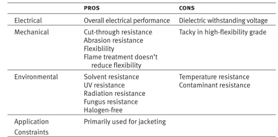
Polyurethane (Figure 2) is a good jacket material, but it is not used in insulation because its dielectric withstanding voltage is low when compared to other materials. Halogen-free grades are available. Mechanically, polyurethane is fl exible, and it is very resistant to cut-through and abrasion. Treatment for fl ame-resistance does not reduce its fl exibility; however, the more fl exible grades tend to be sticky or tacky, which results in a higher coeffi cient of friction. Environmentally, polyurethane is resistant to solvents, UV rays, radiation, and fungus. Polyurethane does not have a very broad temperature range; it becomes brittle around -40°C, and its upper temperature limit is around 100°C.
Figure 2: Properties of Polyurethane
pros cons
Electrical Overall electrical performance Dielectric withstanding voltage Mechanical Cut-through resistance Tacky in high-fl exibility grade
Abrasion resistance
Flexiblility
Flame treatment doesn’t reduce fl exibility
Environmental Solvent resistance Temperature resistance
UV resistance Contaminant resistance
Radiation resistance
Fungus resistance
Halogen-free
Application Primarily used for jacketing
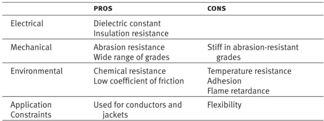
Polyethylene (Figure 3) is most appropriate for conductors, because polyethylene jackets tend to be stiff, which affects the fl exibility of the cable. Polyethylene has good dielectric constant properties when used in conjunction with foam. Mechanically, high-molecular weight polyethylene is abrasion-resistant and low-friction, but it is also stiff when compared to other materials. Like polyurethane, polyethylene’s temperature range is rather limited, and it is diffi cult to bond chemical boots to polyethylene cable jackets. Overall the mechanical properties of polyethylene are reduced by fl ame-retardant treatments.
Figure 3: Properties of Polyethylene
pros cons
Electrical Dielectric constant Insulation resistance
Mechanical Abrasion resistance Stiff in abrasion-resistant
Wide range of grades grades
Environmental Chemical resistance Temperature resistance Low coeffi cient of friction Adhesion
Flame retardance
Application Used for conductors and Flexibility Constraints jackets
Fluoropolymers and Enhanced Fluoropolymers (Figure 4) such as FEP, PFA, PTFE, and engineered PTFE are excellent as insulation and jacket materials, particularly in applications when the cost of system failure is high. The dielectric withstanding voltage of fl uoropolymers is among the highest of any insulation material. Fluoropolymers can withstand extreme tempera-tures, but each material has its own range: FEP can handle temperatures ranging from -250°C to 150°C, while PFA ranges from -250°C to 200°C. PTFE is suitable for temperatures from cryogenic to 260°C without losing fl exibility. Fluoropolymers can also withstand exposure to chemicals, acids, and aggressive solvents, and they are naturally non-fl ammable. PTFE and its co-polymers also have the benefi t of low outgassing, critical for ultra-high vacuum (UHV) environments. Most fl uoropolymers are fl exible, but like temperature-resistance, fl exibility varies depending on the specifi c material, with PFA being the stiffest, then FEP, PTFE, and engineered PTFE being the most fl exible. In addition, anything that is added to a cable’s insulation, jacket, conductors, or shield wires will outgas in a vacuum. Outgassing is not bad in itself; however, when materials outgas, they condense on cooler surfaces, which are typically the work surfaces in the application area. For example, in a satellite, optics can become fogged by silicone oil or other processing lubricants that outgas from a cable. PTFE is chemically inert and does not contain any process additives, oils, lubricants, or plasticizers, which makes it the best material for vacuum environments.
Figure 4: Properties of Fluoropolymers
pros cons
Electrical Dielectric withstanding
voltage
Dielectric constant
Mechanical Flexibility Abrasion and cut-through
Tensile strength resistance
Environmental Liquid and gas resistance Radiation resistance Temperature and UV resistance
No outgassing
Coeffi cient of friction
Application Used as insulation, dielectric, Additional processing required Constraints and jackets
Flame resistance
Performance standards
One of the few negatives of fl uoropolymers is that they are not very resistant to abrasion and cut-through. Certain fl uoropolymers can be engineered to enhance their physical, chemical, and electromagnetic attributes, which improves a cable’s ability to withstand the specifi c challenges of an application. For example, ethylene tetrafl uoroethylene (ETFE) can be irradiated to improve its mechanical properties and chemical resistance; however, irradiation increases stiffness, so there is a signifi cant decrease in fl exibility. On the other hand, PTFE is naturally thermal-resistant and chemically inert, so its excellent temperature and chemical properties are not altered when engineered to enhance electrical or mechanical attributes.
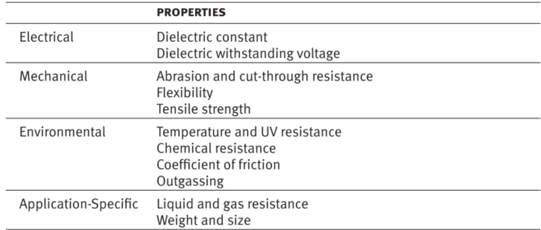
W. L. Gore & Associates has developed proprietary technologies that allow PTFE to be engineered so it can withstand a wide variety of environmental and mechanical challenges (Figure 5). For example, the dielectric materials used to insulate conductors can signifi cantly affect attenuation, cable size, and fl exibility. The lower the dielectric loss, the less attenuation the cable exhibits. Typical fl uoropolymers used in cable insulation have a dielectric loss of 2.1. If cable size is an issue, PTFE can be engineered to have a dielectric constant of 1.3 — the lowest dielectric constant of any material except air. At the same time, its dielectric withstanding voltage can be increased by a factor of 2.5 while achieving a very low loss tangent of 0.0004 at 10 GHz compared to PTFE’s standard construction. With these attributes, a conductor insulated with a 1/2000th-inch or 50-micron layer of ePTFE can be rated for use at 1,000 volts. Gore’s ePTFE is incredibly consistent, allowing for excellent impedance control, minimal impedance variation, and excellent signal balance, which reduce common mode conversion. Another version of engineered PTFE can be made semi-conductive and used to increase the effectiveness of a cable’s shield. For issues of abrasion or cut-through resistance, Gore has engineered PTFE to attain a tensile strength that is 50 times greater than standard PTFE. And for extreme temperatures, Gore has engineered PTFE to withstand temperatures from cryogenic to 300°C. This ability to engineer the physical and electromagnetic attributes of ePTFE results in Gore’s cables being smaller and more fl exible without compromising signal quality.
Figure 5: Enhanced Properties of Gore’s Engineered Fluoropolymers
properties
Electrical Dielectric constant
Dielectric withstanding voltage Mechanical Abrasion and cut-through resistance
Flexibility
Tensile strength
Environmental Temperature and UV resistance
Chemical resistance
Coeffi cient of friction
Outgassing
Application-Specifi c Liquid and gas resistance
Weight and size
Verifying the Cable Design
The second phase of designing a cable system is verifying that it is, in fact,
fi t for the intended application. At a minimum, you should make sure that your manufacturer understands the challenges of your environment and can provide suffi cient data to ensure that the cable will not be compromised. To avoid cable failure in harsh environments, it may be necessary for the manufacturer to develop tests that evaluate electrical performance while simulating mechanical and environmental stress similar to that in your application. At Gore, we have a core value that we call ‘fi tness for use,’ which means that our products do what we say they do. Therefore, we have developed state-of-the-art labs around the world where we test the electrical, mechanical, and environmental performance of cable systems. Most manufacturers perform some level of electrical testing on every cable design before it is approved for delivery, so your basic electrical requirements can be checked against the specifi cations for the cable. Some industries have defi ned safety, environmental, and performance-related standards for cables, but many applications in harsh environments force you to go beyond the standards. In these kinds of situations, you should fi nd out what level of performance testing, if any, the manufacturer has done to ensure that the cable will perform reliably in your application. For example, if the cable has 100 Ohm differential pairs that will be used in a fl exing application, then the cable’s impedance should be monitored while fl ex testing is performed. It is essential to monitor electrical performance and signal integrity throughout testing, and the specifi c type of testing that is needed depends on the environmental constraints of your application.
Mechanical testing verifi es electrical performance while the cable is working in the conditions of your application — conditions such as crushing, abrasion, potential cut-through, tight bending, continuous fl exing, shock, and vibration. For example, applications using hand held devices where cables use the critical motion of random fl exing, an operator may also be pulling it which then tensile strength is an issue. Random fl exing motion is very diffi cult to model in a test lab, so for this type of application, at Gore we run a tic-toc test with repeated bending of 180° or more to model the
worst-case scenario. Then we run a pull test to simulate the cable being used as a tether to pull the lab cart. During these tests, we monitor the controlled impedance as well as the conductor resistance on the shields. Only with this type of testing, can we be confi dent that the cable will handle the mechani-cal and operator stress without compromising signal integrity.
The cable’s electrical performance should also be measured while simulating the environmental conditions in which it will operate — conditions such as temperature, altitude, and pressure extremes; vibration and acceleration; exposure to liquids or gas; or humidity. For example, if you are designing a cable used in an aircraft, temperature cycling and altitude testing will simulate the environment in combination with several mechanical tests. Adding a clamp force during the temperature cycling test allows monitoring
of the insulation’s dielectric withstanding voltage to see how the jacket and conductor changes. Also, it is important to monitor impedance during altitude change, mechanical shock, and vibration tests. After the cable is put through these tests, the manufacturer should again verify the electrical performance, insulation, and jacket materials because you want to ensure that the cable will perform reliability throughout the life of the system.
Throughout the cable selection process, it is important to consider the total cost of ownership. For products that will be used in harsh environments, the consequences of the cable system being compromised or failing are usually high, and the total cost of ownership includes much more than the initial cost to purchase the cable. Total costs should include installation, mainte-nance, and replacement costs; manufacturing downtime and losses due to bad product; and most of all, safety issues. For example, in the aerospace industry reducing mass is a critical issue because every gram of weight adds an additional $60 to the cost of launching a spacecraft. Gore has developed extremely durable cable systems that bundle engineered PTFE with other materials specifi cally for lightweight applications. These systems have enabled aeronautical engineers to reduce cable size by as much as 40 percent, which directly relates to reductions in their launch costs. Another example is a semiconductor manufacturer that was losing millions of dollars in wasted product due to particulation in the production line. By switching to cables specifi cally designed to eliminate particulation, yield has signifi cantly increased and downtime has decreased, which has reduced total operating costs. Both of these examples illustrate the impact that cable systems have on total cost of ownership. Before selecting any cable system, you should do a similar cost analysis to ensure that you have considered the full impact of cable failure.
The following checklist will assist you in identifying the issues you need to discuss with your cable manufacturer when selecting the right cable for your specifi c application and environment. Although you may not be able to complete all of the sections, it will be helpful if you are as specific as pos-sible in the data you can provide.
Understanding Total Cost of Ownership
Type of Application
Military aircraft: Commercial aircraft:
In-fl ight space: Ground test space:
Military equipment: Cleanroom:
Geophysical: Other:
General Requirements
Cable length: Maximum cable diameter:
Total number of cables: Minimum cable diameter:
Data transmission: Digital Analog Protocol/data rate: Other:
Potential Electrical Issues
Voltage rating: Low noise requirements:
Impedance: Crosstalk: Yes No
EMI: Yes No Attenuation: Yes No
Electrostatic discharge: Yes No Other:
Potential Mechanical Issues
Flexing required: Yes No Flex type: Rolling Tic-toc
Cycles: Torsion Random
Bend radius/torsion angle: Stroke length:
Acceleration rate: Speed:
Type of strain relief: Etching/bonding:
Other:
Potential Environmental Issues
Cut-through: Yes No Abrasion: Yes No
Maximum temperature: Minimum temperature:
Humidity: Yes No Chemical exposure type:
Liquid exposure type: Gas exposure type:
Other contaminants: Outgassing: Yes No
Shock/vibration: Yes No Radiation: Yes No
Vacuum (Torr): Cleanroom class: I II III IV
Other:
Application-Specifi c Issues
Weight: Yes No Specifi c weight
requirement:
Routing: Yes No Cable track used:
Human manipulation: Yes No Crush protection: Yes No
Connector type: Regulatory requirements:
UL CSA NEC CE
Other:
Total Cost of Ownership
Installation costs: Impact on operating costs:
Maintenance frequency: Maintenance costs:
Replacement frequency: Replacement costs:
Manufacturing downtime frequency: Downtime costs:
Bad product percentage: Bad product costs:
Safety considerations: Safety costs:
Other:
Worldwide Sales and Support Contact Information China: Beijing +86 10 6408 8060 China: Shanghai +86 21 5172 8299 China: Shenzhen +86 755 8359 8262 Germany +49 9144 6010 India +65 6 733 2882 International +1 302 292 5100 Japan +81 3 6746 2582 Korea +82 2 393 3411 North America 1 800 445 4673 Singapore and ASEAN +65 6 733 2882 Taiwan
+886 2 8771 7799 United Kingdom +44 1382 561511
W. L. Gore & Associates, Inc.
380 Starr Road, Landenberg, PA 19350