Pub. 988-0151-171 www.lowrance.com
X125, X126DF, X135, X136DF
Fish-finding & Depth Sounding Sonars
Operation Instructions
Copyright © 2003 Lowrance Electronics, Inc. All rights reserved.
Lowrance® is a registered trademark of Lowrance Electronics, Inc. Navionics is a registered trademark of Navionics, Inc.
Lowrance Electronics may find it necessary to change or end our policies, regulations and special offers at any time. We reserve the right to do so without notice. All features and specifications subject to change without notice. All screens in this manual are simulated. On the cover: X136DF shown. Other models covered in the manual are similar.
For free owner's manuals and other information, visit our web site:
www.lowrance.com
Lowrance Electronics Inc.12000 E. Skelly Dr. Tulsa, OK USA 74128-2486
Table of Contents
Sec. 1: Read Me First! ... 1
Capabilities and Specifications: X125, X126DF, X135, X136DF.. 2
How Sonar Works ... 3
How to Use this Manual: Typographical Conventions... 4
Sec. 2: Installation & Accessories ... 7
Preparations... 7
Transducer Installation... 7
Recommended Tools and Supplies ... 8
Selecting a Transducer Location... 8
How Low Should You Go?... 9
Shoot-Thru-Hull vs. Transom Mounting ... 10
Transom Transducer Assembly and Mounting ... 10
Trolling Motor Bracket Installation (Single-Frequency only) .. 16
Transducer Orientation and Fish Arches ... 17
Shoot-Thru-Hull Preparation and Installation ... 17
Speed/Temperature Sensors ... 20
Sensor Chart ... 21
Optional Speed Sensor Installation ... 22
Power Connections... 23
Mounting the Unit: Bracket, In-Dash or Portable ... 25
Face Cover... 29
Sec. 3: Basic Sonar Operation... 31
Keyboard ... 31
Power/Lights (Turn Unit On and Off) ... 32
Menus ... 32
Main Menu ... 32
Sonar Menu ... 34
Pages ... 35
Basic Sonar Quick Reference ... 38
Sonar Operations ... 39
Fish Symbols vs. Full Sonar Chart ... 41
Other Free Training Aids ... 42
Sec. 4: Sonar Options & Other Features ... 43
ASP (Advanced Signal Processing) ... 43
Alarms ... 44
Depth Alarms ... 44
Zone Alarm ... 45
Fish Alarm... 46
Brightness ... 46
Calibrate Speed... 46
ii
Depth Cursor... 48
Depth Range - Automatic ... 48
Depth Range - Manual... 49
To Turn Auto Depth Range on Again: ... 49
Depth Range - Upper and Lower Limits ... 49
FasTrack... 51
Fish I.D. (Fish Symbols & Depths) ... 51
FishTrack... 53
FishReveal... 54
Frequency (Change Transducer Frequency) ... 56
Grayline... 57
HyperScroll... 59
Noise Rejection... 59
Overlay Data ... 59
To Change Displayed Data Font Size: ... 60
Ping Speed & HyperScroll... 61
Pop-Up Help ... 62
Reset Options ... 63
Reset Water Distance ... 63
Screen Contrast and Brightness ... 63
Sensitivity & Auto Sensitivity... 64
To Turn Auto Sensitivity Back on:... 66
Set Keel Offset ... 66
Set Language ... 67
Software Version Information... 67
Sonar Chart Mode... 68
Sonar Chart Display Options ... 68
Full Sonar Chart ... 69
Split Zoom Sonar Chart ... 70
Split Frequency Sonar Chart (X126DF and X136DF only) .. 70
Digital Data/Chart ... 71
Customizing the Digital Data/Chart Screen... 72
Flashgraf ... 73
Sonar Simulator... 73
Stop Chart ... 74
Surface Clarity ... 74
Transducer Type (X126DF and X136DF only) ... 75
Units of Measure... 76
Upper and Lower Limits ... 76
Zoom & Zoom Bar ... 76
Zoom Pan... 77
Sec. 5: Sonar Troubleshooting... 79
Section 1: Read Me First!
How this manual can get you out on the water, fast!
Welcome to the exciting world of digital sonar! We know you're anxious to begin finding fish, but we have a favor to ask. Before you grab your unit and begin installing it, please give us a moment or two to explain how our manual can help you get the best performance from your com-pact, wide-screen, fish finder.First, we want to thank you for buying a Lowrance sonar. Whether you're a first time user or a professional fisherman, you'll discover that your unit is easy to use, yet capable of handling demanding sonar tasks. You won't find another sonar unit with this much power and this many features for this price!
Our goal for this book is to get you on the water fast, with a minimum of fuss. Like you, we'd rather spend more time boating or fishing and less time reading the manual!
So, we designed our book so that you don't have to read the whole thing from front to back for the information you want. At the start (or end) of each segment, we'll tell you what content is coming up next. If it's a concept you're already familiar with, we'll show you how and where to skip ahead for the next important topic. We've also made it easy to look up any tips you may need from time to time. Here's how:
The manual is organized into 6 sections. This first section is an intro-duction to the sonar unit. It tells you the basics you need to know be-fore you can make the unit look below the surface to find some fish. Section 2 will help you install your unit and the transducer. We'll also tell you about some of the available accessories.
Section 3 covers Basic Sonar Operation. It will show you how easy it is to run your sonar, right out of the box. This section features a one-page Sonar Quick Reference. (If you've already jumped ahead and fig-ured out how to install the unit yourself, and you just can't wait any longer, turn to the Quick Reference on page 38 and head for the water with your sonar unit!)
After you've gained some experience with your sonar, you'll want to check out Section 4, which discusses more advanced Sonar Options and Other Features.
When you come to a sonar menu command on the unit's screen, you can look it up in the manual by skimming over the table of contents or index, just flipping through Section 3 or scanning through the sonar options in
2
If you're having difficulty with your sonar, you can find an answer to the most common problems in Section 5, Sonar Troubleshooting.
Finally, in Section 6, we offer Supplemental Material, including a list of warranty and customer service information.
Now, if you're into the fine details, glance over the next segment on specifications to see just how much sonar power your unit contains. It's important to us (and our power users), but, if you don't care how many watts of power the unit has, skip ahead to important information on how sonar works, on page 3.
Capabilities and Specifications: X125, X126DF, X135, X136DF General
Display:... 5.0" (12.7 cm) diagonal high contrast Film SuperTwist; programmable to viewing pref-erence.
Resolution:... 480 pixel x 480 pixel resolution ; 230,400 to-tal pixels. 16-level grayscale definition. Backlighting:...X136DF and X135:
White LED backlit screen and keypad. X126DF and X125:
Amber LED backlit screen and keypad. Input power:... 10 to 15 volts DC.
Case size:... 5.4" H x 6.9" W x 3.4" D (13.8 x 17.6 x 8.6 cm); sealed and waterproof; suitable for saltwater use.
Back-up memory:... Built-in memory stores sonar records for decades.
Languages:... 10; menu languages selectable by user. Sonar
Frequency:... 50/200 kHz for X126DF and X136DF; 200 kHz for X125 and X135.
Transducers:... A dual-frequency Skimmer transducer with built-in temperature sensor is packed with the X126DF and X136DF. It has 35°/12° cone angles. A single-frequency with built-in tem-perature sensor is packed with the X125 and X135. It has a 20° cone angle. Transducers operate at speeds up to 70 mph (61 kts).
Transmitter:...X136DF, X135 and X126DF:
4,000 watts peak-to-peak/500 watts RMS. X125:
2,400 watts peak-to-peak/300 watts RMS. Sonar sounding
depth capability:...X136DF: 2,500 feet (762 meters). X126DF: 1,700 feet (518 meters). X135: 1,000 feet (305 meters). X125: 800 feet (244 meters).
Actual capability depends on transducer con-figuration and installation, bottom composi-tion and water condicomposi-tions. All sonar units typically read deeper in fresh water than in salt water.
Depth display:... Continuous display . Audible alarms:... Deep/shallow/fish/zone.
Automatic ranging:... Yes, with instant screen updates. Auto bottom track:... Yes.
Zoom bottom track:... Yes. Split-screen zoom:... Yes. Surface water temp:... Yes.
Speed/distance log:... Optional (requires optional speed sensor). NOTICE!
The storage temperature range for your unit is from -4 degrees to +167 degrees Fahrenheit (-20 degrees to +75 degrees Celsius). Extended stor-age in temperatures higher or lower than specified will damstor-age the liq-uid crystal display in your unit. This type of damage is not covered by the warranty. For more information, contact the factory's Customer Service Department; phone numbers are listed on the last page.
How Sonar Works
Sonar has been around since the 1940s, so if you already know how it works, skip ahead to the next segment on the typographical conventions used in this manual. But, if you've never owned a sonar fish finder, this segment will tell you the under water basics.
Sonar is an abbreviation for SOund NAvigation and Ranging, a technol-ogy developed during World War II for tracking enemy submarines. (Lowrance developed the world's first transistorized sportfishing sonar in
4
1957.) A sonar consists of a transmitter, transducer, receiver and dis-play. In simple terms, here's how it finds the bottom, or the fish:
The transmitter emits an electrical impulse, which the transducer con-verts into a sound wave and sends into the water. (The sound frequency can't be heard by humans or fish.) The sound wave strikes an object (fish, structure, bottom) and bounces back to the transducer, which converts the sound back into an electrical signal.
The receiver amplifies this return signal, or echo, and sends it to the display, where an image of the object appears on the scrolling sonar chart. The sonar's microprocessor calculates the time lapse between the transmitted signal and echo return to determine the distance to the object. The whole process repeats itself several times each second.
How to use this manual: typographical conventions
Many instructions are listed as numbered steps. The keypad and arrow "keystrokes" appear as boldface type. So, if you're in a real hurry (or just need a reminder), you can skim the instructions and pick out what menu command to use by finding the boldface command text. The fol-lowing paragraphs explain how to interpret the text formatting for those commands and other instructions:
Arrow Keys
The arrow keys control a horizontal line depth cursor on the sonar screen. The arrow keys also help you move around the menus so you can execute different commands. They are represented by symbols like these, which denote the down arrow key, the up arrow, the left arrow and the right arrow: ↓↑ ← →.
Keyboard
The other keys perform a variety of functions. When the text refers to a key to press, the key is shown in bold, sans serif type. For example, the "Enter/Icons" key is shown as ENT and the "Menu" key is shown as MENU.
Menu Commands
A menu command or a menu option will appear in small capital letters, in a bold sans serif type like this: DEPTH CURSOR. These indicate that you are to select this command or option from a menu or take an action of some kind with the menu item. Text that you may need to enter or file names you need to select are show in italic type, such as data type.
Instructions = Menu Sequences
Most functions you perform with the sonar unit are described as a se-quence of key strokes and selecting menu commands. We've written them in a condensed manner for quick and easy reading.
For example, instructions for turning on the Fish ID feature would look like this:
1. From the Sonar Page, press MENU|↓ to SONAR FEATURES|ENT. 2. Press → to FISH SYMBOLS|ENT|EXIT|EXIT.
Translated into complete English, step 1 above would mean: "Start on the Sonar Page. Press the Menu key then repeatedly press (or press and hold) the down arrow key to scroll down the menu and select (highlight) the Sonar Features menu command. Then press the Enter key."
Step 2 would mean: "Press the right arrow key to select (highlight) the Fish ID symbols command. Next, press the Enter key, then press the Exit key twice."
6
Section 2:
Installation & Accessories
Preparations
You can install the sonar system in some other order if you prefer, but we recommend this installation sequence:
Caution:
You should read over this entire installation section before drill-ing any holes in your vessel!
1. Determine the approximate location for the sonar unit, so you can plan how and where to route the cables for the transducer and power. This will help you make sure you have enough cable length for the de-sired configuration.
2. Determine the approximate location for the transducer and its cable route.
3. Determine the location of your battery or other power connection, along with the power cable route.
4. Install the transducer and route the transducer cable to the sonar unit.
5. Install the power cable and route it to the sonar unit. 6. Mount the sonar unit.
Transducer Installation
These instructions will help you install your Skimmertransducer on a transom, on a trolling motor or inside a hull. These instructions cover both single- and dual-frequency Skimmer transducers. Please read all instructions before proceeding with any installation.
The smaller single-frequency Skimmers typically use a one-piece, stainless steel mounting bracket. The larger dual-frequency Skimmers typically use a two-piece, plastic mounting bracket. The trolling motor mount uses a one-piece plastic bracket with an adjustable strap.
These are all "kick-up" mounting brackets. They help prevent damage if the transducer strikes an object while the boat is moving. If the trans-ducer does "kick-up," the bracket can easily be pushed back into place without tools.
Read these instructions carefully before attempting the installation. Determine which of the mounting positions is right for your boat. Use
8
extreme care if mounting the transducer inside the hull, because once it is epoxied into position, the transducer usually cannot be removed. Remember, the transducer installation is the most critical part of a sonar installation.
Recommended Tools and supplies
If you prefer the option of routing the cable through the transom, you will need a 1" drill bit. A transom mount requires use of a high quality, marine grade above- or below-waterline caulking compound. The fol-lowing installation types also call for these recommended tools and re-quired supplies (supplies are not included):
Single-frequency transom installations
Tools include: two adjustable wrenches, drill, #29 (0.136") drill bit, flat-head screwdriver. Supplies: none.
Dual-frequency transom installations
Tools: two adjustable wrenches, drill, #20 (0.161") drill bit, flat-head screwdriver. Supplies: four, 1" long, #12 stainless steel slotted wood screws.
Single-frequency trolling motor installations
Tools: two adjustable wrenches, flat-head screwdriver. Supplies: plastic cable ties.
Shoot-through hull installations
Tools: these will vary depending on your hull's composition. Consult your boat dealer or manufacturer. Supplies: 100 grit sandpaper, good quality epoxy adhesive.
Selecting a Transducer Location
1. The transducer must be placed in a location that has a smooth flow of water at all times. If the transducer is to be mounted inside the hull, then the chosen location must be in the water at all times. If the transducer is not placed in a smooth flow of water, interference caused by bubbles and turbulence will show on the sonar's display in the form of random lines or dots whenever the boat is moving. NOTE:
Some aluminum boats with strakes or ribs on the outside of the hull create large amounts of turbulence at high speed. These boats typically have large outboard motors capable of propelling the boat at speeds faster than 35 mph. Typically, a good location on alumi-num boats is between the ribs closest to the engine.
2. The transducer should be installed with its face pointing straight down, if possible.
3. If the transducer is mounted on the transom, make sure it doesn't interfere with the trailer or hauling of the boat. Also, don't mount it closer than approximately one foot from the engine's lower unit. This will prevent cavitation (bubble) interference with propeller operation. 4. If possible, route the transducer cable away from other wiring on the
boat. Electrical noise from engine wiring, bilge pumps and aerators can be displayed on the sonar's screen. Use caution when routing the transducer cable around these wires.
Good and poor transducer locations. How low should you go?
For most situations, you should install your Skimmer transducer so that its centerline is level with the bottom of the boat hull. This will usually give you the best combination of smooth water flow and protec-tion from bangs and bumps.
Align transducer centerline with hull bottom.
However, there are times when you may need to adjust the transducer slightly higher or lower. (The slots in the mounting brackets allow you to loosen the screws and slide the transducer up or down.) If you
fre-CAUTION: Clamp the trans-ducer cable to transom near the transducer. This will help prevent the transducer from entering the boat if it is knocked off at high speed.
Good location
Good location Poor angle
Poor location Good
location
Transom
Hull bottom Transducer
10
quently lose bottom signal lock while running at high speed, the trans-ducer may be coming out of the water as you cross waves or wakes. Move the transducer a little lower to help prevent this.
If you cruise or fish around lots of structure and cover, your transducer may be frequently kicking up from object strikes. If you wish, you may move the transducer a little higher for more protection.
There are two extremes you should avoid. Never let the edge of the mounting bracket extend below the bottom of the hull. Never let the bottom – the face – of the transducer rise above the bottom of the hull. Shoot-thru-hull vs. Transom Mounting
Typically, shoot-thru-hull installations give excellent high speed opera-tion and good to excellent depth capability. There is no possibility of damage from floating objects. It can't be knocked off when docking or loading on the trailer.
However, the shoot-thru-hull installation does have its drawbacks. First, some loss of sensitivity does occur, even on the best hulls. This varies from hull to hull, even from different installations on the same hull. This is caused by differences in hull lay-up and construction. Second, the transducer angle cannot be adjusted for the best fish arches. This can be a problem on some hulls that sit with the bow high when at rest or at slow trolling speeds. Follow the procedure listed in the shoot-thru-hull installation section at the end of this lesson to de-termine if you can satisfactorily shoot through the hull.
TRANSOM TRANSDUCER ASSEMBLY AND MOUNTING
The best way to install these transducers is to loosely assemble all of the parts first, place the transducer's bracket against the transom and see if you can move the transducer so that it's parallel with the ground.
The following instructions sometimes vary depending on the mounting bracket that came with your transducer. Single-frequency Skimmers come with a one-piece stainless steel bracket, while dual-frequency Skimmers come with a two-piece plastic mounting bracket. Use the set of instructions that fits your model.
1. Assembling the bracket.
A. One-piece bracket: Press the two small plastic ratchets into the sides of the metal bracket as shown in the following illustration. Notice there are letters molded into each ratchet. Place each ratchet into the bracket with the letter "A" aligned with the dot stamped into the metal bracket. This position sets the transducer's coarse angle adjustment for a 14° transom. Most outboard and stern-drive transoms have a 14° angle.
Align plastic ratchets in bracket.
B. Two-piece bracket: Locate the four plastic ratchets in the trans-ducer's hardware package. Press two ratchets into the sides of the plas-tic bracket and two on either side of the transducer as shown in the fol-lowing illustrations. Notice there are letters molded into each ratchet. Place the ratchets into the bracket with the letter "A" aligned with the alignment mark molded into the bracket. Place the ratchets onto the transducer with the letter "A" aligned with the 12 o'clock position on the transducer stem. These positions set the transducer's coarse angle adjustment for a 14° transom. Most outboard and stern-drive tran-soms have a 14° angle.
Insert and align ratchets. Dot
Alignment letters Alignment
positions
Transducer bracket Transducer
12
Add ratchets to bracket and transducer. 2. Aligning the transducer on the transom.
A. One-piece bracket: Slide the transducer between the two ratch-ets. Temporarily slide the bolt though the transducer assembly and hold it against the transom. Looking at the transducer from the side, check to see if it will adjust so that its face is parallel to the ground. If it does, then the "A" position is correct for your hull.
If the transducer's face isn't parallel with the ground, remove the transducer and ratchets from the bracket. Place the ratchets into the holes in the bracket with the letter "B" aligned with the dot stamped in the bracket.
Reassemble the transducer and bracket and place them against the transom. Again, check to see if you can move the transducer so it's parallel with the ground. If you can, then go to step 3A. If it doesn't, repeat step 2A, but use a different alignment letter until you can place the transducer on the transom correctly.
Insert bolt and check transducer position on transom. Ratchets
Transducer bracket
Ratchet Ratchet
B. Two-piece bracket: Assemble the transducer and bracket as shown in the following figure. Temporarily slide the bolt though the transducer assembly but don't tighten the nut at this time. Hold the assembled transducer and bracket against the transom. Looking at the transducer from the side, check to see if it will adjust so that its face is parallel to the ground. If it does, then the "A" positions are correct for your hull. If the transducer's face isn't parallel with the ground, remove and disassemble the transducer and ratchets. Place the ratchets into the bracket holes with the letter "B" aligned with the bracket alignment mark. Place them on the transducer aligned with the 12 o'clock posi-tion on the transducer stem.
Reassemble the transducer and bracket and place them against the transom. Again, check to see if you can move the transducer so it's parallel with the ground. If you can, then go to step 3B. If it doesn't, repeat step 2B, but use a different alignment letter until you can place the transducer on the transom correctly.
Assemble transducer and bracket. 3. Assembling the transducer.
A. One-piece bracket: Once you determine the correct position for the ratchets, assemble the transducer as shown in the following fig-ure. Don't tighten the lock nut at this time.
Nut
Metal washer
Metal washer Bolt
Rubber washers
Flat washer Lock washer
Flat washer
Nut Bolt
14
B. Two-piece bracket: Once you determine the correct position for the ratchets, assemble the transducer as shown in the figure in step 2B. Don't tighten the lock nut at this time.
4. Drilling mounting holes.
Hold the transducer and bracket assembly against the transom. The transducer should be roughly parallel to the ground. The trans-ducer's centerline should be in line with the bottom of the hull. Don't let the bracket extend below the hull!
Mark the center of each slot for the mounting screw pilot holes. You will drill one hole in the center of each slot.
Drill the holes. For the one-piece bracket, use the #29 bit (for the #10 screws). For the two-piece bracket, use the #20 bit (for the #12 screws).
Position transducer mount on transom and mark mounting holes. Side view shown at left and seen from above at right. 5. Attaching transducer to transom.
A. One-piece bracket: Remove the transducer from the bracket and re-assemble it with the cable passing through the bracket over the bolt as shown in the following figures.
For single-frequency Skimmer, route cable over bolt and through bracket. Side view shown at left and seen from above at right.
Transom Transom
Both bracket types: Attach the transducer to the transom. Slide the transducer up or down until it's aligned properly with the bottom of the hull as shown in the preceding and following figures. Tighten the bracket's mounting screws, sealing them with the caulking compound. Adjust the transducer so that it's parallel to the ground and tighten the nut until it touches the outer washer, then add 1/4 turn. Don't over tighten the lock nut! If you do, the transducer won't "kick-up" if it strikes an object in the water.
Align transducer centerline with hull bottom and attach transducer to transom. Rear view of dual-frequency Skimmer shown.
6. Route the transducer cable through or over the transom to the sonar unit. Make sure to leave some slack in the cable at the transducer. If possible, route the transducer cable away from other wiring on the boat. Electrical noise from the engine's wiring, bilge pumps, VHF radio wires and cables, and aerators can be picked up by the sonar. Use cau-tion when routing the transducer cable around these wires.
WARNING:
Clamp the transducer cable to the transom close to the transducer. This can prevent the transducer from enter-ing the boat if it is knocked off at high speed.
If you need to drill a hole in the transom to pass the connector through, the required hole size will be 1".
Caution:
If you drill a hole in the transom for the cable, make sure it is lo-cated above the waterline. After installation, be sure to seal the hole with the same marine grade above- or below-waterline seal-ant used for the mounting screws.
Flat-bottom hull Deep-"vee" hull Bottom
of hull
16
7. Make a test run to determine the results. If the bottom is lost at high speed, or if noise appears on the display, try sliding the trans-ducer bracket down. This puts the transtrans-ducer deeper into the water, hopefully below the turbulence causing the noise. Don't allow the transducer bracket to go below the bottom of the hull!
TROLLING MOTOR BRACKET INSTALLATION (single-frequency only)
1. Attach the optional TMB-S bracket to the transducer as shown in the following figure, using the hardware supplied with the transducer. (Note: The internal tooth washer is supplied with the TMB-S.)
Attach motor mounting bracket to transducer.
2. Slide the adjustable strap supplied with the TMB-S through the slot in the transducer bracket and wrap it around the trolling motor. Po-sition the transducer to aim straight down when the motor is in the water. Tighten the strap securely.
3. Route the transducer cable alongside the trolling motor shaft. Use plastic ties (not included) to attach the transducer cable to the troll-ing motor shaft. Make sure there is enough slack in the cable for the motor to turn freely. Route the cable to the sonar unit and the trans-ducer is ready for use.
Transducer mounted on trolling motor, side view. TMB-S bracket Bolt
Internal tooth washer Nut
TRANSDUCER ORIENTATION AND FISH ARCHES
If you do not get good fish arches on your display, it could be because the transducer is not parallel with the ground when the boat is at rest in the water or at slow trolling speeds.
Transducer angles and their effects on fish arches.
If the arch slopes up – but not back down – then the front of the trans-ducer is too high and needs to be lowered. If only the back half of the arch is printed, then the nose of the transducer is angled too far down and needs to be raised.
NOTE:
Periodically wash the transducer's face with soap and water to re-move any oil film. Oil and dirt on the face will reduce the sensitivity or may even prevent operation.
SHOOT-THRU-HULL PREPARATION
The transducer installation inside a fiberglass hull must be in an area that does not have air bubbles in the resin or separated fiberglass
lay-Transducer aimed too far back
Transducer aimed too far forward
Proper transducer angle Partial fish arches
18
transducer installation can be made on hulls with flotation materials (such as plywood, balsa wood or foam) between layers of fiberglass if the material is removed from the chosen area.
Epoxy the transducer to a solid portion of the hull.
For example, some (but not all) manufacturers use a layer of fiberglass, then a core of balsa wood, finishing with an outer layer of fiberglass. Removing the inner layer of fiberglass and the balsa wood core exposes the outer layer of fiberglass. The transducer can then be epoxied di-rectly to the outer layer of fiberglass. After the epoxy cures, the hull is watertight and structurally sound. Remember, the sonar signal must pass through solid fiberglass. Any air bubbles in the fiberglass or the epoxy will reduce or eliminate the sonar signals.
WARNING:
Do not remove any material from your inner hull unless you know the hull's composition. Careless grinding or cutting on your hull can result in damage that could sink your boat. Contact your boat dealer or manufacturer to confirm your hull specifications.
To choose the proper location for thru-hull mounting, anchor the boat in 60 feet of water. Add a little water to the sump of the boat. Plug the transducer into the sonar unit, turn it on, then hold the transducer over the side of the boat. Adjust the sensitivity and range controls until a sec-ond bottom echo is seen on the display. (You will need to turn off both automatic and ASP.) Don't touch the controls once they've been set. Next, take the transducer out of the water and place it in the water in the sump of the boat. Observe the sonar signal to see if there is a no-ticeable decrease in sensitivity. The second bottom signal may disap-pear and the bottom signal may decrease in intensity.
Move the transducer around to find the best location. If the sensitivity control must be increased greatly to compensate, then the transducer should be mounted on the outside of the hull. If not, then mark the
lo-Fill with polyester resin
Inner hull
Epoxy to hull first
Outer hull Flotation material
cation that shot through the hull the best and follow the instructions on the following pages for a shoot-thru-hull mounting.
Shoot-thru-hull transducer locations for high speed or trolling speed operation. Shoot-thru-hull Installation
1. Make sure the area is clean, dry and free of oil or grease, then sand both the inside surface of the hull and the face of the transducer with 100 grit sandpaper. The surface of the hull must be flat so the entire transducer face is in contact with the hull prior to bonding.
Epoxy transducer to hull.
2. Follow the instructions on the epoxy package and mix it thoroughly. Do not mix it too fast, because it will cause bubbles to form in the ep-oxy. Apply a small amount on the face of the transducer as shown above, then spread a small amount onto the sanded area on the hull.
Transducer location (trolling speed) Transducer location
(high speed)
Spread epoxy here
20
Place the transducer into the epoxy, twisting and turning it to force any air bubbles out from under the transducer face. The face of the transducer should be parallel with the hull, with a minimum amount of epoxy between the hull and transducer. After the epoxy dries, route the cable to the sonar unit.
Speed/Temperature Sensors
This unit accepts up to three temperature sensors which can monitor surface water, live well, bait well and virtually any other temperature. If you want to use more than one temperature sensor or a speed sensor, you must purchase the optional MY-4X adapter cable. You also need to be careful when purchasing the temperature sensors, because each temperature sensor has its own fixed electronic "address." The sensors are labeled "Water," "T-2" (or Temp-2) and "T-3" (or Temp-3).
The first "Water" temperature sensor is built into the transducer. This is the sensor that measures surface water temperature. If you want two (or more) temperature readings from other locations, you'll need to use the proper sensors. For example, you can't use two additional T-3 sen-sors. The sensors that fit this unit are:
• TS-1X This sensor will over-ride the temperature sensor built into the transducer and over-ride the tem-perature sensor in a ST-TGY combination sen-sor. (This sensor is not recommended.)
• TS-2X One sensor for "T-2" temperature display. • TS-3X One sensor for "T-3" temperature display. • SP-X One speed sensor for "Speed" display.
• ST-TGY This combination sensor will provide speed and temperature readings, but the temperature reading will be displayed as the "Water" tem-perature because it will over-ride the tempera-ture sensor in the transducer. (This sensor is not recommended.)
See the wiring diagram on the following page for temperature and speed sensor combinations.
Sensor Chart
Two-temperature sensor installation
Three-temperature sensor installation with speed Three-temperature sensor installation
TS-3X
temperature sensor
SP-X speed sensor MY-4X
Cable TS-2X
temperature sensor Temperature
sensor built into transducer Sonar unit
22
Optional Speed Sensor Installation
All the units in this series can display speed and distance traveled, but only the X126DF and X136DF come packed with a speed sensor. If you wish to purchase an optional additional sensor for your unit, refer to the accessory ordering information inside the back cover of this man-ual. The following instructions describe how to install the speed sensor. Recommended tools for this job include: drill, 7/8" drill bit, 1/8" drill bit for pilot holes, screwdriver. Required supplies for this job include: four #8 stainless steel wood screws (3/4" long), high quality, marine grade above-or below-waterline caulking compound.
First find a location on the boat's transom where the water flow is smooth-est. Don't mount the sensor behind strakes or ribs. These will disturb the water flow to the speed sensor. Make sure the sensor will remain in the water when the boat is on plane. Also make sure the location doesn't inter-fere with the boat's trailer. Typically, the sensor is mounted about one foot to the side of the transom's centerline.
Once you've determined the proper location for the unit, place the sen-sor on the transom. The bottom of the bracket should be flush with the hull's bottom. Using the sensor as a template, mark the hull for the screws' pilot holes. Drill four 1/8" holes, one in each end of the slots. Mount the sensor to the hull using #8 stainless steel wood screws (not included). Use a high quality, marine grade above- or below-waterline caulking compound to seal the screws. Make sure the sensor is flush with the bottom of the hull and tighten the screws.
Stern view showing good location for mounting sensor on transom.
Speed sensor mounting configuration: side view (left) and rear view (right.) Good location
Transom
Bottom of hull Bottom of hull
If the base of the transom has a radius, fill the gap between the tran-som and the sensor with the caulking compound. This will help ensure a smooth water flow.
Route the sensor's cable through or over the transom to the sonar unit. If you need to drill a hole in the transom to pass the connector through, the required hole size is 7/8".
Caution:
If you drill a hole in the transom for the cable, make sure it is lo-cated above the waterline. After installation, be sure to seal the hole with the same marine grade above- or below-waterline seal-ant used for the screws.
The sensor is now ready for use. Connect the sensor to the in-line con-nector on the MY-4X adapter cable. If you have any questions concern-ing the installation of the sensor, please contact your local boat dealer.
Power Connections
The unit works from a 12-volt battery system. For the best results, at-tach the power cable directly to the battery. You can atat-tach the power cable to an accessory or power buss, however you may have problems with electrical interference. Therefore, it's safer to go ahead and attach the power cable directly to the battery.
CAUTION:
When using the unit in a saltwater environment, we strongly rec-ommend that you shut off the power supply to the power cable when the unit is not in use. When the unit is turned off but still connected to a power supply, electrolysis can occur in the power cable plug. This may result in corrosion of the plug body along with the electri-cal contacts in the cable and the unit's power socket.
In saltwater environments we recommend you connect the power cable to the auxiliary power switch included in most boat designs. If that results in electrical interference, or if such a switch is not available, we recommend connecting direct to the battery and in-stalling an inline switch. This will let you shut off power to the power cable when the unit is not in use. When you are not using the unit, you should always shut off power to the power cable, es-pecially when the power cable is disconnected from the unit.
If possible, keep the power cable away from other boat wiring, espe-cially the engine's wires. This will provide the best isolation from elec-trical noise. If the cable is not long enough, splice #18 gauge wire onto it. The power cable has two wires, red and black. Red is the positive
24
lead, black is negative or ground. Make sure to attach the in-line fuse holder to the red lead as close to the power source as possible.
For example, if you have to extend the power cable to the battery or power buss, attach one end of the fuse holder directly to the battery or power buss. This will protect both the unit and the power cable in the event of a short. It uses a 3-amp fuse.
Power connections for the sonar unit. CAUTION:
Do not use this product without a 3-amp fuse wired into the power cable! Failure to use a 3-amp fuse will void your warranty.
This unit has reverse polarity protection. No damage will occur if the power wires are reversed. However, the unit will not work until the wires are attached correctly.
An optional 8-foot, CA-4 external power cable with a cigarette lighter adapter is available from Lowrance.
12 volt battery
Black wire Red wire with
3 amp fuse To unit
Optional power off switch for saltwater installations
Sonar unit cable connections.
Mounting the Unit: Bracket, In-Dash or Portable
You can install the sonar unit on the top of a dash with the supplied gimbal bracket. It can also be installed in the dash or mounted on a portable power supply.
If you use the supplied bracket, you may be interested in the optional R-A-M bracket mounting system. This converts the unit's gimbal bracket to a swivel mount, which can be used on the dash or overhead mounting positions. Installation instructions are supplied with the R-A-M mounting kits.
Sonar unit rear view
Power socket
Power wires
Sonar socket
26
Optional R-A-M mounting system. Bracket Installation
Mount the unit in any convenient location, provided there is clearance behind the unit when it's tilted for the best viewing angle. You should also make sure there is enough room behind the unit to attach the power and transducer cables. (A drawing on the next page shows the dimensions of a gimbal-mounted sonar unit.)
Holes in the bracket's base allow wood screw or through-bolt mounting. You may need to place a piece of plywood on the back side of thin fiber-glass panels to reinforce the panel and secure the mounting hardware.
Install the gimbal bracket. Orient the bracket so the arms slope toward the front of your unit.
Drill a 1-inch (25.4 mm) hole in the dash for the power and transducer cables. The best location for this hole is immediately under the gimbal
bracket location. This way, the bracket can be installed so that it covers the hole, holds the cables in position and results in a neat installation. Some customers, however, prefer to mount the bracket to the side of the cable hole — it's a matter of personal preference.
Front view (left) and side view (right) showing dimensions of the sonar unit when mounted on gimbal bracket.
After drilling the hole, pass the transducer connector up through the hole from under the dash. Pass the power cable's bare-wire end down though the hole from the top.
If you wish, you can fill in the hole around the cables with a good ma-rine caulking compound. (Some mama-rine dealers stock cable hole covers to conceal the opening.) No matter what type of installation you prefer, be sure to leave enough slack in the cables to allow tilting or swiveling the unit. If you choose to fill in the hole, be sure to position the cables against the rear edge of the hole as you apply the fill material.
Before positioning the bracket, be sure to hold the cables against the rear edge of the hole. Then, slide the bracket over the hole and butt the rear of the bracket base firmly against the cables, thus pinning them in place against the side of the hole. Finally, fasten the bracket to the dash. Attach the unit to the gimbal bracket using the supplied gimbal knobs and washers.
Millimeter [Inch]
23.4 [0.92] 72.9 [2.87]
137.9 [5.43]
56.9 [2.24] 157.9
[6.22] 173.9
28
In-Dash Installation
You can mount the unit in the dash with an optional FM-5 In-Dash Adapter Kit. The kit includes mounting hardware, a template for cut-ting the hole and an instruction sheet, part 988-0147-43.
In-dash mounting template for the sonar unit, showing dimensions. NOTE: The figure above is not printed to scale. A scaled template (FM-5 In-Dash Adapter Kit instructions) is available for free
download from our web site, www.lowrance.com. Portable Installation
Like many Lowrance products, this sonar unit is capable of portable operation by using the optional PPP-11 portable power pack. The power pack and an optional portable transducer expand the uses for your so-nar unit. The PPP-11 makes it easy to use the unit on your boat or take it to the dock, on a float tube, on an ice fishing trip or use it as a second sonar in a friend's boat.
The PPP-11 Portable Power Pack can be used with eight "D" cell alka-line batteries or an optional sealed, rechargeable battery. For set-up directions, refer to the pack's instruction sheet, part 988-0147-46.
113.5 [4.46]
Millimeters [Inches]
ALWAYS VERIFY DIMENSIONS
In-Dash
Template
R 7.9 [0.31] 146.5
[5.76]
Install batteries in power pack battery adapter.
Face Cover
Your unit comes with a white protective cover that snaps on and off the front of the unit. This cover is intended for use when your unit and the vehicle it's mounted in are idle.
WARNING:
When the unit is mounted in an unprotected area, such as an open boat cockpit, the protective face cover must be removed when the vehicle is moving at high speed. This includes towing a boat on a trailer at highway speeds. Otherwise, wind blast can pop off the cover.
30
Section 3: Basic Sonar Operation
This section addresses the unit's most basic sonar operations. The in-structions presented here in Sec. 3 follow a chronological order. Sec. 4, Sonar Options & Other Features, will discuss options and other more advanced functions and utilities. The material in Sec. 4 is arranged in alphabetical order.
Before you turn on the unit, it's a good idea to learn about the different keys, the Main Menu, the Sonar Menu, the five Page options and how they all work together. BUT, if you just can't wait to get on the water, turn to the one-page Quick Reference on page 38.
Keyboard
Sonar unit, front view, with keyboard. X136DF shown.
1. PWR/LIGHT (Power & Light) – The PWR key turns the unit on and off and activates the backlight.
2. PAGES – Pressing this and the ↑↓ arrow keys switches the unit be-tween the five different page options. (Full Sonar Chart, Split Zoom So-nar Chart, Split Frequency SoSo-nar Chart, Digital Data and FlashGraf .) 3. MENU – Press this key to show the menus and submenus, which
5
4
2 8
7 9
6 3
32
4. ARROW KEYS – These keys are used to navigate through the menus, make menu selections, move the sonar chart cursor and enter data. 5. ENT (Enter) – This key allows you to accept values or execute menu commands.
6. EXIT – The Exit key lets you return to the previous screen, clear data or erase a menu.
7. ALARM – The Alarm key is a quick shortcut to the sonar alarms menu. It allows you to choose which alarms to use and when.
8. ZOUT – (Zoom Out) – This key lets you zoom the screen out. This key returns you to a full sonar chart display, showing the entire water column from surface to bottom.
9. ZIN – (Zoom In) – This key lets you zoom the screen in. It enlarges fish signals, bottom detail and other sonar returns.
Power/lights on and off
To turn on the unit, press PWR.
To change the backlight, press PWR again. The X125 and X126DF have two backlight levels to select from. The X135 and X136DF have three backlight levels. Repeatedly pressing PWR will cycle through the back-light settings, turn off the backback-light, then turn it back on again.
Turn off the unit by pressing and holding the PWR key for about 3 seconds.
Menus
Your sonar unit will work fine right out of the box with the factory de-fault settings. You only need to learn a few basic functions to enhance your viewing. We'll discuss them briefly here, then talk about them and all the other commands in more detail in the next section, which begins on page 43.
Your unit has three primary menus that control its operation. They are the Main Menu, the Sonar Menu and the Pages Menu.
Main Menu
The Main Menu contains some basic function commands and some setup option commands. You access the Main Menu by pressing MENU|MENU. You run a command by using the ↑ or ↓ to highlight the command and then pressing ENT. To clear the Main Menu screen and return to the Page display, press EXIT. (Remember, our text style for "MENU|MENU" means "press the Menu key twice." See a full explanation of our instruc-tion text formatting on page 5, Instrucinstruc-tions = Menu Sequences.)
Main Menu. Main Menu Commands
There are four "basic" Main Menu commands that you'll really want to read more about. They are:
• Screen command: changes the contrast or brightness of the display screen. Use this command to adjust how the screen looks under various lighting conditions.
• Sounds command: enables or disables the sounds for key strokes and alarms, controls the volume and sets the alarm style. If you don't like to hear a beep each time you press a key, you can turn this off, or select tunes or sound effects instead. The sounds are especially useful when used with the Fish I.D. fish symbol feature and fish alarm feature. • Sonar Alarms command: turns alarms on or off and changes alarm thresholds. The fish alarm, used with Fish I.D., is the most popular use. It tells you when the sonar sees a fish. You can also set deep or shallow depth alarms and zone alarms.
• Popup Help command: turns the pop-up help boxes on or off. When you select a menu command, these information boxes appear to tell you what the command does or how to use the command. The default set-ting is on, which is really handy while you're learning.
The remaining Main Menu commands are for more advanced functions, mostly setting various sonar options. (They're all detailed in Sec. 4.) • Units of Measure command: selects the units of measure used for showing speed/distance, depth and temperature.
• Set Keel Offset command: calibrates the unit to show depth under the keel or actual depth from the surface.
34
• Reset Water Distance command: resets water distance log to zero. • Sonar Simulator command: turns the simulator feature on and off. Useful for learning how to operate the unit and all its functions.
• Transducer Type command (dual-frequency units only): sets the type of transducer plugged into the unit.
• Reset Options command: returns all options and auto functions to their original factory settings. It's a great safety net while you're learning and experimenting with various settings.
• Set Language command: your unit has menus in 10 different lan-guages. This command switches from one language to another.
• Software Information command: tells you which version of the op-erating software is loaded in your unit.
Sonar Menu
The Sonar Menu contains commands for the major sonar features and options. You access the Sonar Menu by pressing the MENU key one time. You run a command by using the ↑ or ↓ to highlight the command and then pressing ENT. To clear the menu screen and return to the Page display, press EXIT.
Sonar Page Menu. Most of these functions are discussed in Sec. 4. Sonar Menu Commands
The Sonar Menu contains commands for the major sonar features and options. Most of them are only described in detail in Sec. 4, but Sensitiv-ity and Auto SensitivSensitiv-ity are important basic functions that are discussed both here and in Sec. 4. The other Sonar Menu commands include: • Grayline command: separates fish and structure near the bottom from the actual bottom, and defines bottom composition/hardness. • Depth Range command: manually sets the depth range shown on the sonar chart.
• Auto Depth Range command: automatically sets the depth range shown on the sonar chart to always keep the bottom in view.
• Upper and Lower Limits command: sets the upper and lower depth limits of the sonar chart. Lets you zoom in on a specific portion of the water column.
• Stop Chart command: stops the sonar chart from scrolling. Used when you want to "freeze" the image for closer study.
• Chart Speed command: sets the scrolling speed of the sonar chart. • Depth Cursor command: displays a cursor line on the sonar chart which allows you to accurately measure the depth of a sonar target. • Overlay Data command: chooses what types of information (such as water temperature) to show overlaid on the sonar chart screen.
• Sonar Features command: launches the Sonar Features menu which controls many functions and options, including frequency selection, screen color mode, auto depth and sensitivity, surface clarity, noise re-jection, Fish I.D. symbols, the zoom bar and zone bar.
• Ping Speed command: sets the rate at which sonar pings are made.
Pages
The Pages Menu controls the five major display options. They are the Full Sonar Chart, Split Zoom Sonar Chart, Split Frequency Sonar Chart, Digital Data and the flasher-style FlashGraf.
You access the Pages Menu by pressing the PAGES key. You select a display option by using ↑ or ↓ to highlight the option and then pressing ENT. (You can clear the Pages Menu by pressing EXIT.)
36
The Full Sonar Chart is the main display option. This is a "cross-section" view of the water column beneath the boat. The chart moves across the screen, displaying sonar signal echoes that represent fish, structure and the bottom.
Sonar Page, showing full sonar chart mode.
Sonar chart display options (from left) split zoom (all models) and split frequency (X126DF and X136DF only).
Surface clutter
Structure
Bottom signal Fish arches
In FasTrack, fish arches show as horizontal bars.
Depth scale Digital data
overlay (depth & temperature)
Surface signal
Zoom bar
FasTrack bar graph
Sonar chart display options (from left) digital data and FlashGraf. You can customize how the Sonar Page pictures and other data are dis-played in many ways. We'll discuss all of those features and options in Section 4, but to show you how easy the sonar unit is to operate, the fol-lowing page contains a simplified, 10-step quick reference that will cover most fish finding situations. The quick reference describes how your unit will operate with all the sonar features in their automatic modes, which are set at the factory.
38
Basic Sonar Quick Reference
1. Mount the transducer and unit. Connect the unit to electric power and the transducer.
2. Launch your boat.
3. To turn on the unit, press and release PWR key.
4. Head for your fishing grounds. Your unit automatically displays digi-tal depth and surface water temperature in the corner of the screen. The auto settings will track the bottom, displaying it in the lower por-tion of the screen. The full sonar chart will scroll from right to left, showing you what's under the boat as you cruise across the water. 5. As you're watching the sonar returns, you can change the display by: Zoom in to enlarge the chart for more detail: press ZIN.
Zoom out to return to full chart mode: press ZOUT.
6. If necessary, adjust sensitivity to improve chart readability. Press MENU|ENT and the Sensititvy Menu will appear on the left of your screen. Use ↑ and ↓ to change the setting.
Boosting sensitivity will show more information on your screen, which may cause clutter. Reducing sensitivity will filter out some information, but could omit important images. We recommend adjusting sensitivity until the background is lightly "peppered" — that is, scattered dots ap-pear, but individual objects (like fish arches or bottom structure) can be easily picked out of the background.
7. Watch the display for the appearance of fish arches. When you see arches, you've found fish! Stop the boat and get your lure or bait into the water at the depth indicated on the sonar chart.
8. Gauge the fish depth by visually comparing the fish arches with the depth scale on the right side of the screen, or get a more accurate measure with the Depth Cursor. Press MENU|↓ to DEPTH CURSOR|ENT. Press ↓ (or ↑) to align the cursor line with the fish arch. The exact depth appears in a box at the right end of the cursor line. To clear the cursor, press EXIT.
9. If you are drifting at a very low speed or anchored, you are not mov-ing fast enough for a fish to return the tell-tale fish arch signal. As you drift over a fish, or as a fish swims through the transducer's signal cone, the fish echo will appear as a straight line suspended between the surface and the bottom.
Sonar Operations
As you can see from the quick reference on the previous page, basic operation is pretty easy, right out of the box. If you are a sonar novice, try operating the unit with the factory defaults until you get a feel for how it's working.
As you're learning the basics, there is one setting you might want to tinker with from time to time — Sensitivity.
Sensitivity controls the unit's ability to pick up echoes. If you want to see more detail, try increasing the sensitivity, a little at a time. There are situa-tions when too much clutter appears on the screen. Decreasing the sensitivity can reduce the clutter and show the strongest fish echoes, if fish are present. As you change the sensitivity setting, you can see the difference on the chart as it scrolls.
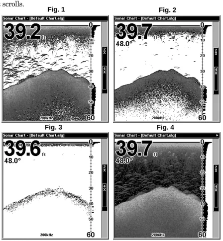
These figures show results of different sensitivity levels on the same location. Fig. 1: Sensitivity at 88 percent, determined by Auto
Sensitiv-ity. Typical of full auto mode. Fig. 2: Sensitivity set at 75 percent. Fig. 3: Sensitivity set at 50 percent. Fig. 4: Sensitivity set at 100 percent.
Fig. 1 Fig. 2
40
You can change the sensitivity level whether you are in Auto Sensitiv-ity mode or Manual SensitivSensitiv-ity mode. The adjustment method works the same in both modes, but it gives you slightly different results. Adjusting sensitivity in Auto Sensitivity Mode is similar to manually ad-justing a car's speed with the accelerator pedal while cruise control is on. You can tell the car to run faster, but when you let off the gas the cruise control automatically keeps you from running slower than the minimum speed setting. In the sonar unit, auto mode will let you increase sensitiv-ity to 100 percent, but the unit will limit your minimum setting. This pre-vents you from turning sensitivity down too low to allow automatic bot-tom tracking. When you change the setting with auto turned on, the unit will continue to track the bottom and make minor adjustments to the sen-sitivity level, with a bias toward the setting you selected.
Adjusting sensitivity in Manual Sensitivity Mode is similar to driving a car without cruise control — you have complete manual control of the car's speed. In the sonar unit, manual mode allows you to set sensitiv-ity at 100 percent (maximum) or zero percent (minimum.) Depending on water conditions, the bottom signal may completely disappear from the screen when you reduce sensitivity to about 50 percent or less! Try adjusting sensitivity in both auto and manual modes to see how they work.
To adjust sensitivity: 1. Press MENU|ENT.
2. The Sensitivity Control Bar appears. Press ↓ to decrease sensitivity; press ↑ to increase sensitivity. When it's set at the desired level, press EXIT. (When you reach the maximum or minimum limit, a tone sounds.)
At left, Sonar Menu with Sensitivity command selected. At right, the Sensitivity Control Bar.
NOTE:
If you want to change the sensitivity in Manual Mode, first turn off Auto Sensitivity: from the Sonar Page, press MENU|↓ to AUTO SENSITIVITY|ENT|↑ to SENSITIVITY|ENT. Press ↓ or ↑ to pick a different sensitivity setting. When it's set at the desired level, press EXIT.
Important Tip:
While you are experimenting and learning, it's possible to scramble the settings so that the sonar picture disappears from your screen. If that happens, remember that it's easy to switch back to full automatic operation by simply restoring the factory auto settings. Here's how:
To Restore Factory Settings
1. Press MENU|MENU|↓ to RESET OPTIONS|ENT.
2. The unit asks if you want to reset all the options. Press ← to YES|ENT. All options are reset, and the unit reverts back to the original settings.
Fish Symbols vs. Full Sonar Chart
You may have noticed in the quick reference that we used fish arches in full sonar chart mode for our example, and not the popular Fish I.D. fish symbol feature. Here's why.
Fish I.D. is an easier way for a sonar novice to recognize a fishy signal return when he sees it. However, locating fish by symbol only has some limitations.
Your sonar unit's microprocessor is remarkably powerful, but it can be fooled. Some of the echoes calculated to be fish could be tree limbs or turtles! To see what's under your boat in maximum detail, we recom-mend you turn off Fish I.D. and begin learning to interpret fish arches. Fish I.D. is most handy when you're in another part of the boat or per-forming some task that prevents you from watching the sonar screen. Then, you can turn on Fish I.D. and the audible fish alarm. When that lunker swims under your boat, you'll hear it!
Fish I.D. can also be useful when you want to screen out some of the sonar detail gathered by your unit. For example, in one case fishermen in San Francisco Bay saw clouds of clutter in the water but no fish arches. When a down rigger was pulled up, it brought up several small jellyfish. The fishermen switched their Lowrance sonar to Fish I.D., which screened out the schools of jellyfish and clearly showed the game fish there as fish symbols.
42
Other Free Training Aids
The sonar options section discusses Fish I.D., fish alarms and other features in greater detail. If you or a friend has Internet access, you can also learn more about interpreting what you see on your sonar screen. Visit our web site, WWW.LOWRANCE.COM. Be sure to check out the free Sonar Tutorial, which includes animated illustrations and more pic-tures of actual sonar returns, all described in detail. There's even a "printer friendly" version of the tutorial available on our web site…it makes a great supplement to this operation manual!
For the ultimate training aid, be sure to download the free emulator software for your unit. Aside from being just plain fun, this program can help you learn both basic and advanced operations without burning boat fuel! Lowrance is the first sonar manufacturer to provide this type of training tool for customers.
This PC application simulates the actual sonar unit on your computer. You can run it from your computer keyboard or use your mouse to press the virtual keys. Easy download and installation instructions are avail-able on our web site.
Section 4: Sonar Options & Other Features
Material in this section is arranged in alphabetical order. ASP (Advanced Signal Processing)
The ASP feature is a noise rejection system built into the sonar unit that constantly evaluates the effects of boat speed, water conditions and interference. This automatic feature gives you the best display pos-sible under most conditions.
The ASP feature is an effective tool in combating noise. In sonar terms, noise is any undesired signal. It is caused by electrical and mechanical sources such as bilge pumps, engine ignition systems and wiring, air bubbles passing over the face of the transducer, even vibration from the engine. In all cases, noise can produce unwanted marks on the display. The ASP feature has four settings — Off, Low, Medium and High. If you have high noise levels, try using the "High" ASP setting. However, if you are having trouble with noise, we suggest that you take steps to find the interference source and fix it, rather than continually using the unit with the high ASP setting.
There are times when you may want to turn the ASP feature off. This allows you to view all incoming echoes before they are processed by the ASP feature.
At left, Sonar Menu with Sonar Features selected. In the Sonar Features menu, Noise Rejection is selected with ASP in the default low
setting (center, dual-frequency menu; at right, single-frequency menu). To change the ASP level:
1. From the Sonar Page, press MENU|↓ to SONAR FEATURES|ENT. 2. Press ↓ to NOISE REJECTION|ENT.
3. Press ↓ or ↑ to select a setting, then press ENT. 4. To return to the previous page, press EXIT|EXIT.
44
Alarms
This unit has three different types of sonar alarms. The first is the Fish Alarm. It sounds when the Fish I.D. feature determines that an echo is a fish.
Another alarm is the Zone Alarm, which consists of a bar on the side of the screen. Any echo on the chart that appears inside this bar triggers this alarm.
The last alarm is the Depth Alarm, which has both a Shallow and a Deep setting. Only the bottom signal will trigger this alarm. This is useful as an anchor watch, a shallow water alert or for navigation. Depth Alarms
The depth alarms sound a tone when the bottom signal goes shallower than the shallow alarm's setting or deeper than the deep alarm's set-ting. For example, if you set the shallow alarm to 10 feet, the alarm will sound a tone if the bottom signal is less than 10 feet. It will continue to sound until the bottom goes deeper than 10 feet.
The deep alarm works just the opposite. It sounds a warning tone if the bottom depth goes deeper than the alarm's setting. Both depth alarms work only off the digital bottom depth signals. No other targets will trip these alarms. These alarms can be used at the same time or individually.
At left, Main Menu and Sonar Alarms command. At right, the Sonar Alarms menu.
To adjust and turn on the shallow alarm: 1. Press ALARM.
2. Press → to SHALLOW ALARM DEPTH|ENT.
3. Press ↑ or ↓ to change the first number, then press → to move the cursor to the next number and repeat until the depth is correct, then press ENT.
5. To turn off the alarm, press ALARM|ENT|EXIT.
To switch to a different depth setting, open the Sonar Alarms menu and repeat the instructions in step 3 above.
To adjust and turn on the deep alarm: 1. Press ALARM.
2. Press ↓ to DEEP ALARM ENABLED|→ to DEEP ALARM DEPTH|ENT.
3. Press ↑ or ↓ to change the first number, then press → to move the cursor to the next number and repeat until the depth is correct, then press ENT.
4. Press ← to DEEP ALARM ENABLED|ENT|EXIT.
5. To turn off the alarm, press ALARM|↓ to DEEP ALARM E N-ABLED|ENT|EXIT.
To switch to a different depth setting, open the Sonar Alarms menu and repeat the instructions in step 3 above.
Zone Alarm
The zone alarm is triggered when any echo passes inside the zone alarm bar, shown on the right side of the screen.
To adjust and turn on the zone alarm: 1. Press ALARM.
2. Press ↓ to ZONE ALARM ENABLED|→ to ADJUST ZONE|ENT.
At left, Sonar Alarms menu, with Adjust Zone command selected. At right, Adjust Zone Alarm selection box, with Upper selected. 3. To set the upper boundary for the Zone Alarm, use ← or→ to select UPPER, then press ↑ or ↓ to move the top of the bar to the desired depth. 4. To set the lower boundary for the Zone Alarm, use ← or→ to select LOWER, then press ↑ or ↓ to move the bottom of the bar to the desired depth. 5. Press EXIT|← to ZONE ALARM ENABLED|ENT|EXIT. Now, any echo —
46
ger the zone alarm.
6. To turn off the alarm, press ALARM|↓ to ZONE ALARM E N-ABLED|ENT|EXIT.
To switch to a different depth setting, open the Sonar Alarms menu and repeat the instructions in steps 3 and 4 above.
Fish Alarm
Use the fish alarm for a distinctive audible alarm when fish or other suspended objects are detected by the Fish I.D. feature (Fish I.D. must be turned on for the Fish Alarm to work). a different tone sounds for each fish symbol size shown on the display.
Sonar Alarms menu with Fish Alarm selected. The check box to the left is blank, indicating the alarm is turned off.
To turn the fish alarm on: 1. Press ALARM.
2. Press ↓ to FISH ALARM|ENT|EXIT.
3. To turn off the alarm, press ALARM|↓ to FISH ALARM|ENT|EXIT.
Brightness
See the entry in this section for Screen Contrast and Brightness.
Calibrate Speed
The speed sensor can be calibrated to compensate for inaccuracies. Be-fore you change the setting, first calculate the percentage that the speed is off. You will enter this percentage in a moment.
For example, if you figure the sensor is reading 10 percent faster than actual speed, you will enter – 10 in the calibration window. If the sen-sor is reading 5 percent slower than true speed, you will enter + 5 in the window.
Perform your test in relatively calm water free of current, if possible. (Unless, of course, you are taking the current speed into consideration
when making your calculation.) After you have a correction figure, here's how to enter it:
1. Press MENU|MENU|↓ to CALIBRATE WATER SPEED|ENT.
2. Enter the number you calculated earlier: press ↑ or ↓ to change the first character (+ or –), then press → to move the cursor to the next number and repeat until the percentage is correct, then press EXIT.
Chart Speed
The rate that echoes scroll across the screen is called the chart speed. The default is maximum; we recommend that you leave the speed set there for virtually all fishing conditions.
However, you might consider experimenting with chart speed when you are stationary or drifting very slowly. You may sometimes achieve bet-ter images as you slow down the chart speed to match how fast you are moving across the bottom.
If you are at anchor, ice fishing or fishing from a dock, experiment with a chart speed around 50 percent. If you are drifting slowly, try a chart speed around 75 percent. When you are stationary and a fish swims through the sonar signal cone, the image appears on the screen as a long line instead of a fish arch. Reducing the chart speed may result in a shorter line that more closely resembles a regular fish return.
At left, Sonar Page menu with Chart Speed command selected. At right, Chart Speed Control Bar.
If you do experiment with chart speed, remember to reset it to maxi-mum when you resume trolling or moving across the water at higher speed. To change chart speed:
1. From the Sonar Page, press MENU|↓ to CHART SPEED|ENT.