sp. z o.o. ul. Raciborskiego 51/3, 80-215 Gdańsk
tel. 058-345 39 22, 058-345 39 23, fax 058-345 39 15
strona 1z1
Installation and operation manual
Converter I-7188En-MGTCP
Modbus TCP to Modbus RTU Gateway
and
Router I-7188En-MRTCP
Modbus RTU to Modbus TCP Router.
GDAŃSK 09.2006
sp. z o.o. ul. Raciborskiego 51/3, 80-215 Gdańsk
TABLE OF CONTENTS
GENERAL DESCRIPTION ...3
INTRODUCTION...3
APPLICATION...3
MODBUS GATEWAY INSTALLATION BLOCK DIAGRAM. ...3
MODBUS GATEWAY OPERATION PRINCIPLE...3
MODBUS ROUTER INSTALLATION BLOCK DIAGRAM...4
MODBUS ROUTER OPERATION PRINCIPLE...4
BLOCK DIAGRAM OF MODBUS ROUTER AND GATEWAY IN ONE SYSTEM. ...4
ACCESORIES SUPPLIED WITH CONVERTER...5
CONFIGURATION ...6
LOCAL CONFIGURATION - RS232 ...6
CONNECTING CONVERTER TO PC COMPUTER...6
OPERATOR CONSOLE “7188XW.EXE” ... 7
AVAILABLE COMMANDS FOR ETHERNET NETWORK PROTOCOL CONFIGURATION... 8
EXAMPLES OF CORRECT AND INCORRECT CONFIGURATION OF NETWORK ADDRESS (IP,MASK, GATEWAY) ... 9
AUXILIARY COMMANDS, AVAILABLE IN “7188XW.EXE” CONSOLE... 10
REMOTE CONFIGURATION – TCP/ETHERNET...11
GENERAL NOTES... 11
USED TCP COMMUNICATION PORTS... 12
”TELNET.EXE” CONSOLE START IN CONVERTER CONFIGURATION MODEA... 12
CONFIGURATION COMMANDS, AVAILABLE THROUGH “TELNET.EXE” ... 14
sp. z o.o. ul. Raciborskiego 51/3, 80-215 Gdańsk
tel. 058-345 39 22, 058-345 39 23, fax 058-345 39 15
strona 3z3
General description
Introduction
This documentation contains the description of basic functionality of converters and does not exhaust all possible technical parameters and application of those devices. Converters may be equipped, according to the requirements, with the additional data recorder module or mini WWW server, allowing for preview of Modbus registries in online mode.
If You are looking for such devices with non-typical functions, please contact our company by e-mail [email protected] or phone +48 58 345 39 22.
Application
Converters of Gateway or Router type are designed for conversion between Modbus TCP and Modbus RTU protocol, and vice versa. Below three most typical installation methods are presented.
Modbus Gateway installation block diagram.
Modbus Gateway operation principle
Converter from the Ethernet side operates as Modbus TCP Slave. This allows for receiving incoming TCP connections from Modbus TCP master. Received query is converted to Modbus RTU standard and sent through the serial port to Slave RTU device. Then converter switches into waiting mode on the serial port for the response. If in the
sp. z o.o. ul. Raciborskiego 51/3, 80-215 Gdańsk preset time (1000 ms by default) Slave RTU returns the answer, it is converted by the converter into Modbus TCP standard and sent back to the TCP Master.
Modbus Router installation block diagram.
Modbus Router operation principle
Converter from the RS-232 or RS-485 serial port side operates as Modbus RTU Slave. This allows for receiving communication frames of Modbus RTU protocol, coming from Modbus RTU master. Received query is converted into Modbus TCP standard, and the destination device IP address is determined upon the basis of so called Modbus Routing Table, connecting Modbus RTU address with IP address. Then the Modbus TCP query is sent through the serial port to the Modbus Slave TCP device. Then converter switches into waiting mode on the Ethernet port for the response. If in the preset time (1000 ms by default) Slave TCP returns the answer, it is converted by the converter into Modbus RTU standard and sent back to the RTU Master.
sp. z o.o. ul. Raciborskiego 51/3, 80-215 Gdańsk
tel. 058-345 39 22, 058-345 39 23, fax 058-345 39 15
strona 5z5
Accesories supplied with Converter
Full set of I-7188En-MxTCP Converter includes:
1. Converter with symbol I-7188E1 (one serial communication port COM1-RS232) or 7188E2 (two serial communication ports COM1-RS232 i COM2-RS485)
2. There is software installed in Converter, adjusting it to realizing proper Gateway functions from Modbus TCP to Modbus RTU (I-7188En-MGTCP) or Router from Modbus RTU to Modbus TCP (I-7188En-MRTCP).
3. Cable for Converters configuration from PC computer through port RS232.
4. FDD 1,44” or CD, containing software “7188xw.exe”, allowing for converter configuration through serial port RS232.
5. DIN installation strip, approximately 15 cm long. 6. Set of clamped pipe ends.
sp. z o.o. ul. Raciborskiego 51/3, 80-215 Gdańsk
Configuration
Converters configuration procedure is divided into two stages.
In the first stage it is necessary to configure Ethernet network interface parameters through serial port RS232.
In the second stage, if necessary, it is possible to configure other Converter parameters. However configured default parameters usually allow for proper Converter operation.
Local configuration - RS232
Connecting Converter to PC computer
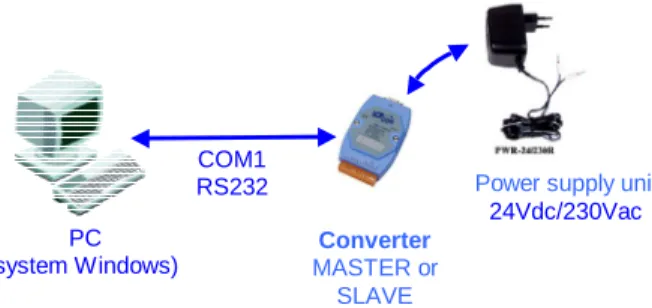
To start Converter local configuration procedure, connect supplied RS232 cable to Converter COM1 port according to terminals description on cable ends. Connect DB9 plug to serial port RS232 of PC computer. It is very important to connect terminal “INIT*” to power supply ground (GND).
Details of individual connections are shown below.
After all above connections turn on Converter power supply.
Fig. Block diagram of connections for Converter configuration
Fig. Detailed diagram of connections for Converter configuration
COM1 RS232 Converter MASTER or SLAVE PC (system Windows) RS232 cable
Converter 7188E1 or 7188E2
Ethernet interface
Power supply unit10-30Vdc
Power supply unit
sp. z o.o. ul. Raciborskiego 51/3, 80-215 Gdańsk
tel. 058-345 39 22, 058-345 39 23, fax 058-345 39 15
strona 7z7 Operator console “7188xw.exe”
Converter in configured with use of “7188xw.exe” program, included on supplied CD. It is communication interface in form of text terminal between master PC computer and Converter. Through serial port RS232 it is possible to configure controller and perform software update.
7188xw.exe program is designed for operation in Windows 2000/NT system. In case of Windows 98 system use it is necessary to use 7188x.exe program.
sp. z o.o. ul. Raciborskiego 51/3, 80-215 Gdańsk
Available commands for Ethernet network protocol configuration
From operator console level user may assign network configuration static parameters to controller:
- IP number using “setip” command example: „setip 192.168.5.56”+’Enter’
- subnet mask (MASK) using “setmask” command example: „setmask 255.255.255.0”+’Enter’ - gate (GATEWAY) using “setgateway” command
example: „segateway 192.168.5.1”+’Enter’
Result of exemplary entering of configuration procedure is shown below:
NOTES:
1. IP number and default gate (GATEWAY) MUST be configured as addresses of the same Ethernet network segment. If they are programmed as addresses of different subnets, it may cause improper operation of 7188E1 controller.
2. If in Ethernet network, where 7188E1 devices are installed, the is no computer with GATEWAY function, e.g. when communication within the same network segment is realized, then it is necessary to configure default gate as IP number of any computer of the same network segment.
It is important, because 7188E1 device during restart performs communication test through triple sending ICMP packet to address configured as GATEWAY. If computer with that address is not available in network, then 7188E1 device restart procedure may
be prolonged of 3 to 4 . seconds
In particular for case described in that paragraph it is possible to program IP address of another 7188E1 device from mutually communicating pair as GATEWAY.
sp. z o.o. ul. Raciborskiego 51/3, 80-215 Gdańsk
tel. 058-345 39 22, 058-345 39 23, fax 058-345 39 15
strona 9z9 Examples of correct and incorrect configuration of network address (IP,MASK,
GATEWAY)
Below there are examples of correct and incorrect configuration of network addresses
Example of CORRECT configuration of IP and GATEWAY numbers: - IP = 192.168.1.175
- GATEWAY = 192.168.1.1 or 192.168.1.156 or 192.168.1.x or .... - MASK = 255.255.255.0
Example of INCORRECT configuration of IP and GATEWAY numbers: - IP = 10.0.1.5
- GATEWAY = 10.0.45.1 or 192.168.0.1 or 192.168.5.5 or ... - MASK = 255.255.255.0
- Converter does not accept IP and GATEWAY from different subnets.
Below there is message presented, which appears in console window “7188xw.exe” after command “cp”+’Enter’ in case of incorrectly configured network interface parameters (IP, MASK, GATEWAY).
sp. z o.o. ul. Raciborskiego 51/3, 80-215 Gdańsk
Auxiliary commands, available in “7188xw.exe” console
Besides Ethernet network interface parameters configuration, from “7188xw.exe” console level it is possible to:
Check Converter MAC address
Command: “mac”+’Enter’
After its execution in console window Current Convertr MAC address is displayed. Example of this command execution is shown below:
sp. z o.o. ul. Raciborskiego 51/3, 80-215 Gdańsk
tel. 058-345 39 22, 058-345 39 23, fax 058-345 39 15
strona 11z11
Remote configuration – TCP/Ethernet
After initial configuration of network interface parameters (IP, MASK, GATEWAY) through port RS232, Converter may be connected to Ethernet network and configured through that interface with use of Telnet console.
Brand new Converter has default parameters configured. Usually such configuration is sufficient for correct Converter operation. The only exception is the necessity of current updating of Modbus Routing Table in the Converter operating as Modbus Router I-7188En-MRTCP.
Remote configuration may be also performed after Converter installation in place of destination.
General notes
7188En device may be configured with use of Telnet console, available as standard tool is Windows2000/NT/XP system.
Program is started by clicking “Start” button in Windows taskbar, and selecting “Run” command. In window type: telnet nnn.nnn.nnn.nnn TCPport, where:
nnn.nnn.nnn.nnn – IP number of 7188E1 device to connect with TCPport –TCP port number
Used TCP ports numbers are described in further paragraph of this manual.
sp. z o.o. ul. Raciborskiego 51/3, 80-215 Gdańsk
Used TCP communication ports
The following TCP ports numbers are implemented in the device:
1. 502 – ModbusTCP communication – sending of communication frames between MASTER and SLAVE Converters.
2. 10500 – port used for communication correctness tracking 3. 10750 – port used for Converter configuration
4. 11000 – SATCHWELL communication – sending of communication frames for SATCHWELL controllers. Protocols SNP and NCP.
”Telnet.exe” console start in Converter configuration modea
To start Telnet console for remote Converter configuration, use the following command ‘telnet nnn.nnn.nnn.nnn 10750’
Access to Converter configuration is protected by default with password: ‘1234 5678’. Enter that password from keyboard, when window shown below appears:
Finish password entering with ‘Enter’ key.
sp. z o.o. ul. Raciborskiego 51/3, 80-215 Gdańsk
tel. 058-345 39 22, 058-345 39 23, fax 058-345 39 15
strona 13z13
Operator may then enter further devices configuration commands.
sp. z o.o. ul. Raciborskiego 51/3, 80-215 Gdańsk
Configuration commands, available through “Telnet.exe” 1. Reading of current configuration:
Description command causes displaying of current configuration parameters
in console window
Syntax GETCONF Parameters
(description) None Performed operation
result Displaying of current configuration parameters on screen Example of use Getconf
“Telnet.exe” console view after getconf command:
After that command all available configuration parameters are displayed. User should however modify only parameters described in this manual.
CAUTION: all configuration parameters do not fit in one console window. To view all of them, use scroll bar on the console right side.
sp. z o.o. ul. Raciborskiego 51/3, 80-215 Gdańsk
tel. 058-345 39 22, 058-345 39 23, fax 058-345 39 15
strona 15z15 2. Introducing Modbus Routing Table
This command allows for defining IP SLAVE Converter addresses pairs and Modbus RWS address.
Description this command allows for setting IP address of remote device
7188E1
Syntax SETADDR [ADDR] [NNN.NNN.NNN.NNN] Parameters
(description) [ADDR] – address Modbus [NNN.NNN.NNN.NNN] – IP address for remote SLAVE Converter Performed operation
result Writing of new configuration of IP and Modbus Address in the EEPROM memory Notes Restart 7188E1 devices after configuration parameters
modification.
Example of use setaddr 1 192.168.1.175
CAUTION! Maximum Modbus address, serviced by the MASTER converter
63
sp. z o.o. ul. Raciborskiego 51/3, 80-215 Gdańsk
3. Configuration of serial port COM1 parameters
Description command allows to configure parameters of the first serial port
COM1
Syntax SETCOM [PORT] [BAUD] [DATA_FORMAT] [PARITY] [STOPBITS] Parameters
(description) [port] –COM port number – in this case 1 [baud] – transmission rate
[data_format] - data format [parity] – parity
[stopbits] – stop bits number
Performed operation
result Saving new COM1 configuration in EEPROM memory Notes Restart 7188E1 devices after configuration parameters
modification.
Example of use setcom 1 2400 8 0 1
4. Setting timeout (response time) for communication through serial port COM1
Description command allows to set timeout (response time) in TCP communication through serial port.
Syntax SETTIMEOUTRS [TIMEOUT] Parameters
(description) [TIMEOUT] –timeout in [ms] Performed operation
result Saving new timeout value in EEPROM memory
Notes Restart 7188E1 devices after configuration parameters modification.
Example of use settimeoutrs 900
5. Setting interruption time in transmission through the serial port, considered as Modbus RTU frame end
Description this command allows for setting interruption time in transmission
through the serial port, considered as Modbus RTU frame end
Syntax SETPAUSE [TIME] Parameters
(description) [TIME] –timeout in [ms] Performed operation
result Saving new timeout value in EEPROM memory
Notes Restart 7188E1 devices after configuration parameters modification.
sp. z o.o. ul. Raciborskiego 51/3, 80-215 Gdańsk
tel. 058-345 39 22, 058-345 39 23, fax 058-345 39 15
strona 17z17 6. Checking of configured IP address for remote device 7188E1
Description this command displays in the console window the currently
configured Modbus addresses and the corresponding IP addresses
Syntax GETADDR Parameters
(description) none Performed operation
result Displaying of current addresses values on the screen
Notes For the solution dedicated for Energomats of APATOR production
always the last Modbus address and the corresponding IP number is taken into consideration.
Example of use getaddr
Telnet console view after the getaddr command:
sp. z o.o. ul. Raciborskiego 51/3, 80-215 Gdańsk 7. Setting timeout (response time) for communication through Ethernet network
Description command allows to set timeout (response time) in TCP
communication session in Ethernet network
Syntax SETTIMEOUTTCP [TIMEOUT] Parameters
(description) [TIMEOUT] –timeout in [ms] Performed operation
result Saving new timeout value in EEPROM memory
Notes Restart 7188E1 devices after configuration parameters
modification.
sp. z o.o. ul. Raciborskiego 51/3, 80-215 Gdańsk
tel. 058-345 39 22, 058-345 39 23, fax 058-345 39 15
strona 19z19 Recommended configuration for MASTER and SLAVE Converters
The configuration shown below is set by default in each MASTER or SLAVE Converter.
Serial port COM 1 :
CV: COM1_Port =[ 1] .... EEPROM: COM1_Port =[ 1]
CV: COM1_Baud =[ 9600] .... EEPROM: COM1_Baud =[ 9600]
CV: COM1_Data =[ 8] .... EEPROM: COM1_Data =[ 8]
CV: COM1_Parity =[ 0] .... EEPROM: COM1_Parity =[ 0]
CV: COM1_Stop =[ 1] .... EEPROM: COM1_Stop =[ 1]
Serial port COM 2 : CV: COM2_Port =[ 2] .... EEPROM: COM2_Port =[ 2]
CV: COM2_Baud =[ 9600] .... EEPROM: COM2_Baud =[ 9600]
CV: COM2_Data =[ 8] .... EEPROM: COM2_Data =[ 8]
CV: COM2_Parity =[ 0] .... EEPROM: COM2_Parity =[ 0]
CV: COM2_Stop =[ 1] .... EEPROM: COM2_Stop =[ 1]
TCP/IP ports : CV: ModbusPort =[ 502] .... EEPROM: ModbusPort =[ 502]
CV: ConfigPort =[ 10750] .... EEPROM: ConfigPort =[ 10750]
CV: DebugPort =[ 10500] .... EEPROM: DebugPort =[ 10500]
CV: SatchPort =[ 11000] .... EEPROM: SatchPort =[ 11000]
Main config settings : CV: Pause =[ 4] .... EEPROM: Pause =[ 4]
CV: MoadbusID =[ 1] .... EEPROM: MoadbusID =[ 1]
CV: ModAtStart =[ 1] .... EEPROM: ModAtStart =[ 1]
CV: EnPassword =[ 1] .... EEPROM: EnPassword =[ 0]
CV: HostEnable =[ 0] .... EEPROM: HostEnable =[ 0]
CV: EnFirConfig =[ 0] .... EEPROM: EnFirConfig =[ 0]
CV: EnAcceptBroadcast =[ 0] .... EEPROM: EnAcceptBroadcast =[ 0]
CV: NumberConnectTrials =[ 3] .... EEPROM: NumberConnectTrials =[ 3]
CV: ConnectingTimeout =[ 500] .... EEPROM: ConnectingTimeout =[ 500]
CV: CloseSocketTimeout =[ 10] .... EEPROM: CloseSocketTimeout =[ 10]
CV: DisconectModbus =[ 0] .... EEPROM: DisconectModbus =[ 0]
CV: TimeoutRS =[ 900] .... EEPROM: TimeoutRS =[ 900]
CV: TimeoutTCP =[ 1000] .... EEPROM: TimeoutTCP =[ 1000]
CV: AlwaysFirstIp =[ 0] .... EEPROM: AlwaysFirstIp =[ 0]
CV: _CHK_CRC_ =[ 0] .... EEPROM: _CHK_CRC_ =[ 0]
CV: MaxTimeSocketLive =[ 0] .... EEPROM: MaxTimeSocketLive =[ 0]
CV: MaxTimeSocketIdle =[ 45] .... EEPROM: MaxTimeSocketIdle =[ 45]
CV: MaxTimeCommSocketIdle=[ 0] .... EEPROM: MaxTimeCommSocketIdle=[ 0]
CV: MinFreeSockets =[ 5] .... EEPROM: MinFreeSockets =[ 5]
CV: TimeoutNetExchg =[ 60] .... EEPROM: TimeoutNetExchg =[ 60]
CV: TimeoutCOMExchg =[ 0] .... EEPROM: TimeoutCOMExchg =[ 0]
TCP upload settings : CV: RequestForUpdate =[ 0] .... EEPROM: RequestForUpdate =[ 0]
CV: StatusUpdateDone =[ 0] .... EEPROM: StatusUpdateDone =[ 0]
CV: CountUpdates =[ 0] .... EEPROM: CountUpdates =[ 0]
CV: CountReset =[ 0] .... EEPROM: CountReset =[ 0]
CV: EnTCPMod =[ 1] .... EEPROM: EnTCPMod =[ 1]
CV: MaxResetCount =[ 0] .... EEPROM: MaxResetCount =[ 0]
CV: TCPUpdateTimeout =[ 60] .... EEPROM: TCPUpdateTimeout =[ 60]
CV: TimeAutoClearReqForUpdate=[ 15] .... EEPROM: TimeAutoClearReqForUpdate=[ 15]
DHCP settings : CV: EnDHCP =[ 0] .... EEPROM: EnDHCP =[ 0]
CV: TimeoutDHCP =[ 10] .... EEPROM: TimeoutDHCP =[ 10]
CV: DHCPLeaseTime =[4294967295] .... EEPROM: DHCPLeaseTime =[4294967295]
CV: EnAutoDisableDHCP =[ 0] .... EEPROM: EnAutoDisableDHCP =[ 0]
CV: EnDHCPAfterPWROn =[ 0] .... EEPROM: EnDHCPAfterPWROn =[ 0]
CV: EnDHCPAfterModFail =[ 0] .... EEPROM: EnDHCPAfterModFail =[ 0]
CV: EnDHCPDebug =[ 0] .... EEPROM: EnDHCPDebug =[ 0]
CV: Password1 =[1234] .... EEPROM: Password1 =[1234]
sp. z o.o. ul. Raciborskiego 51/3, 80-215 Gdańsk
CV: CryptIdent =[no crypt] .... EEPROM: CryptIdent =[no crypt]
In most cases set configuration parameters are sufficient for correct Converters operation and should not be modified.
Technical support for these devices may be obtained directly from the producer:
TechBase Sp. z o.o.
www.a2s.pl
[email protected] tel. +48 58 345 39 22