O R I G I N A L R E S E A R C H
Open Access
Integrated protection based on
multi-frequency domain information for UHV
half-wavelength AC transmission line
Qingping Wang
*, Zhiqian Bo, Xiaowei Ma, Ming Zhang, Yingke Zhao, Yi Zhu and Lin Wang
Abstract
Half-wavelength AC Transmission (HWACT) can improve capability of AC transmission significantly. According to the basic principle of HWACT, the electromagnetic transient model of HWACT is built to analyze the fault transient process of transmission line. Based on fault characteristics of HWACT, the adaptability of traditional protections for transmission lines is analyzed briefly, such as current differential protection, distance protection and over current protection. In order to solve the problems of conventional protection caused by HWACT, a novel integrated protection based on multi-frequency domain information is proposed in this paper, which uses both the power frequency information and transient information. The integrated protection based on multi-frequency domain information takes advantages of power frequency and transient protections, which can not only improve the performance of traditional protection of AC transmission line but also realize fast fault judgment by transient travelling wave protection.
Keywords:Half-wavelength AC transmission, Relaying protection, Electromagnetic transient simulation, Travelling wave
Introduction
In order to support UHV long-distance transmission, the Half-wavelength AC Transmission (HWACT) is pre-sented to improve capability of AC transmission, whose electric transmission distance is close to a half of the power frequency wavelength. It is a three-phase AC transmission technology used for extremely long dis-tance, such as three thousand kilometers at 50Hz or two kilometers and five hundred kilometers at 60Hz. In a vast country, HWACT technology is very attractive be-cause it’s a way of long distance, large capacity transmis-sion. In recent years, many countries have launched the positive research on it, such as Brazil and Korea. Under the development strategy of Global Energy Internet of China, long distance, large capacity transmission is an inevitable way, but the relay protection technology is one of problems troubling the engineering application of HWACT technology all the time [1].
Voltage and current distribution of half-wavelength line is very different from the characteristic of short line [2–6]. The voltage and current of two terminals don’t follow the Kirchhoff’s law based on the lumped parame-ters no longer, the measured impedance are no longer monotonic with distance [7–10]. The traditional protec-tion principle cannot be used on half-wavelength line. In a word, the traditional relay protection principle cannot be directly applied on half-wavelength line. HWACT technology is proposed by the Soviet scholars in the 1940s [11], but research on relay protection of half-wavelength power system, is very less at home and abroad. A line current differential protection principle based on Bergeron model for half-wavelength AC trans-mission line is proposed in [7] and [10], based on the measured values and calculated values with Bergeron model on one side of the line, but it is impressionable by the line parameter. Paper [8] analyzes the applicability of current differential protection and distance protection, and proposes compensation algorithms of differential current calculation and interphase impedance
calcula-tion, but don’t involve ground impedance calculation.
* Correspondence:[email protected]
Corporate R&D Center, XJ group, State Grid Corporation of China, Beijing, China
Overall, the research on relay protection technology of half-wavelength transmission is in the initial stage. It need much deeper research on a large number of technical problems about protection principle and algorithm, the protection configuration and setting, and so on [12–16].
According to the basic principle of HWACT, the elec-tromagnetic transient model of HWACT is built to sup-port fault transient process analysis. Based on fault characteristics of HWACT, the adaptability of traditional protections for transmission lines is analyzed briefly, such as current differential protection, distance protec-tion and over current protecprotec-tion. A novel integrated protection based on multi-frequency domain informa-tion is proposed in this paper, which uses both the power frequency information and transient information. The advantages and implementation of integrated pro-tection for UHV half-wavelength AC transmission line are described in this paper at last.
Methods
Principle of half-wavelength AC transmission
Structure & principle of half-wavelength AC transmission The transmission distance of half-wavelength AC trans-mission is close to a half of the power frequency wave-length, which is 3000 km at 50Hz. The half-wavelength power system researched is show in Fig. 1. The length of line MN is 3000 km, and the left side is connected to a power station group, the right side is connected to a big power grid. The direction of power flow is from M to N at normal operation.
When the line is equal to or longer than 250 km, we must consider the influence of the distributed parame-ters, to get more precise model of the line. The distrib-uted parameter model of HVAC transmission line is shown in Fig. 2.
Set line series impedance of per length unit is equal to z, shunt admittance is equal to y, then z = r + jωL, y = g
+ jωC. The voltage and current of any point on the
transmission line with x far from the end is as follows:
Vð Þ ¼x coshγx VRþZcsinhγxIR ð1Þ
I xð Þ ¼Z1
c sinhγx VRþ coshγxIR ð2Þ
Zcis the characteristic impedance, be equal to
ffiffi
z y
q .γis the propagation constant, be equal to αþjβ¼pffiffiffiffiffizy ¼pðffiffiffiffiffiffiffiffiffiffiffiffiffiffiffiffiffiffiffiffiffiffiffiffiffiffiffiffiffiffiffiffiffiffiffiffiffiffiffirþjωLÞðgþjωCÞ , and the real part α is the
attenuation constant, the imaginary part β is the phase
constant. Under lossless situation, the relation of voltage and current at the head and end is:
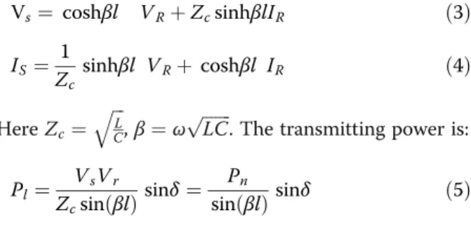
Vs¼ coshβl VRþZcsinhβlIR ð3Þ
IS ¼Z1
c sinhβl VRþ coshβl IR ð4Þ
HereZc¼
ffiffiffi
L C
q
,β¼ωpffiffiffiffiffiffiffiLC. The transmitting power is:
Pl¼ZVsVr
csinð Þβl sinδ¼
Pn
sinð Þβl sinδ ð5Þ
Vsand Vr are the voltages of the head and end, Pnis
natural power,δ is the angleVsahead ofVr. It thus
ap-pears that, when βl is equal to 180°, length of line is half-wavelength line, and Pl can reach infinity in ideal
conditions. Because β¼ωpffiffiffiffiffiffiffiLC¼ω=ð3108Þlis equal to 3000 km at 50Hz.
Characteristics of half-wavelength AC transmission
As a kind of super long distance transmission scheme, half-wavelength AC transmission technology has unique economic and technical advantages.
1. Half-wavelength transmission line needn’t reactive power compensator. Regardless of how power flow changes, the voltages of sending end and receiving end are always consistent.
2. Transmission capacity of half-wavelength transmis-sion line is bigger, can reach infinity in ideal conditions.
3. Half-wavelength transmission needn’t add switching station on the line, because it needn’t reactive compensation and has high stability margin.
4. The economy of half-wavelength transmission is better. According to preliminary estimates by Brazil, 1000 kV HWACT’s transmission cost of per unit length and per unit power is 29.8% of 500 kV EHV’s[6].
Although half-wavelength AC transmission technology has so many advantages, it still has some technical
Fig. 1System structure of half-wavelength AC transmission
difficulties in the engineering application, described as follows:
1. Overvoltage problem. It includes steady overvoltage and fault overvoltage.
2. Secondary arc current problem. When single-phase earth fault occurrd, secondary arc current of half-wavelength transmission line is bigger than the con-ventional line.
3. Security and stability problems. When half-wavelength line suffers from a large disturbance, it will appear power angle stability problem and dy-namic stability problem.
4. Protection problem. The fault electrical characteristics of voltage and current are very different from the short line’s, due to the long line and large distributed capacitance, it will have a large effect on tranditional protection principle and setting principle.
Electromagnetic transient model of half-wavelength AC transmission
In order to analyze the fault transient process, the elec-tromagnetic transient model of half-wavelength AC transmission line is built in this paper. The normal elec-tromagnetic transient models of transmission line
in-clude π-sections model, Bergeron model and frequency
dependent model.
π-section model
Aπ-section model will give the correct fundamental im-pedance, but cannot accurately represent other frequen-cies unless many sections are use, shown in Fig. 3. It is suitable for very short lines where the travelling wave models cannot be used, due to time step constraints. It is definitely unsuitable to the half-wavelength AC trans-mission line which is the extra long distance transmis-sion system about 3000 km.
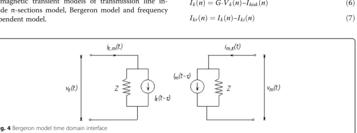
Bergeron model
The Bergeron model represents the system L and C in a distributed manner, shown in Fig. 4. In fact, it is roughly equivalent to using an infinite number of series-connected p-sections except that the total system
resist-ance R is lumped. As with π-sections, the Bergeron
model accurately represents system parameters at the fundamental frequency.
Because the Bergeron model is not frequency-dependent (calculates at a single frequency), it is suitable for studies where frequencies other than the fundamen-tal are of little or no concern. The Bergeron model is ac-curate enough to research the protection based on fundamental frequency, but cannot be used to analyze transient travelling waves.
Frequency dependent model
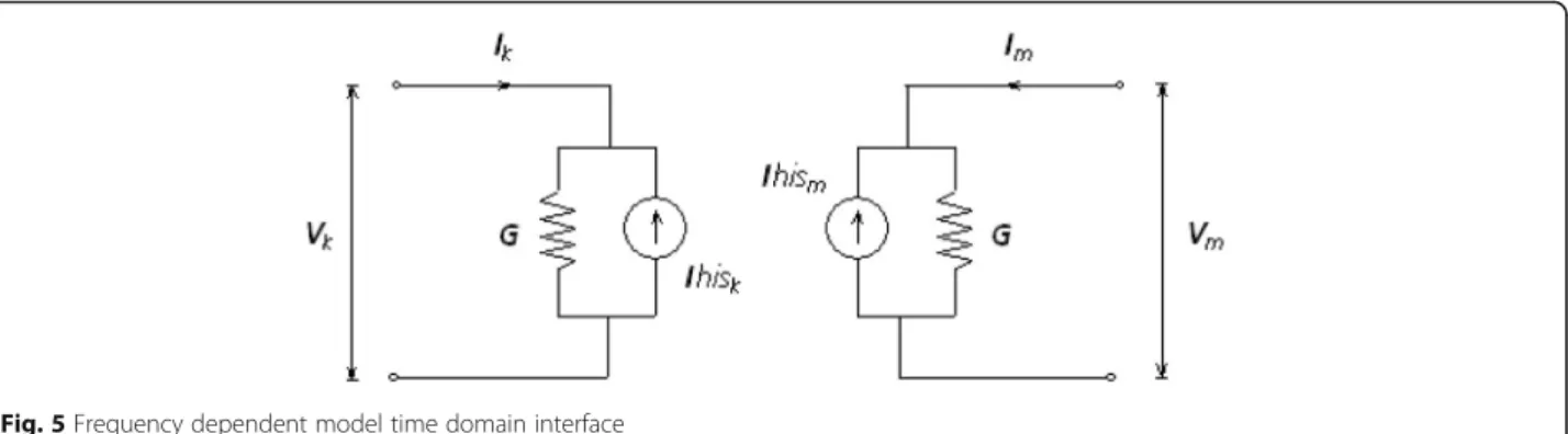
The frequency dependent model is a type of distributed traveling wave model. The system resistance R is distrib-uted across the system length instead of lumped at the end points. The Frequency Dependent Phase model is interfaced to the electric network by means of a Norton equivalent circuit, shown in Fig. 5.
The history current source injectionsIhiskandIhismare
updated each time step, given the node voltages Vkand
Vm. The steps by which this is accomplished by the
Fre-quency Dependent Phase Model time-domain interface routine is as given in below:
Ikð Þ ¼n G⋅Vkð Þ−n Ihiskð Þn ð6Þ
Ikrð Þ ¼n Ikð Þ−n Ikið Þn ð7Þ
Fig. 3π-section equivalent circuit
Ikiðnþ1Þ ¼HImrðn−τÞ ð8Þ
Ihiskðnþ1Þ ¼Y′cVkð Þ−n 2⋅Ikiðnþ1Þ ð9Þ
The frequency dependent models are solved at a num-ber of frequency points, which considers the frequency dependence of internal transformation matrices. Unlike the Bergeron model, these models also represent the total system resistance R as a distributed parameter (along with a distributed system L and C), providing a much more accurate representation of attenuation. It is the ideal electromagnetic transient model for half-wavelength AC transmission lines, which can be used to research transient protection based on travelling wave.
Fault transient analysis for half-wavelength AC transmission
In order to analyze the adaptability of traditional protec-tion for the half-wavelength transmission line, the fault characteristics at different fault points are researched in this paper. The three-phase short circuit characteristics are shown as an example. It can be seen from the figures that, when faults happen along the line, the short circuit characteristics of the half-wave length AC transmission line is totally different from normal transmission line.
Voltage & current characteristics of short circuit
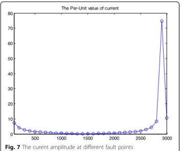
When the fault happens on arbitrary position along the Half-Wave transmission line, the amplitude of voltages and current at different fault point is shown in Figs. 6 and 7.
As shown in Fig. 6, the voltages increase when the distance between the beginning and the fault position in-creases until the distance reaches 2900 km. Then the measured voltage decreases quickly when the fault hap-pens in the last 100 km.
The current decreases firstly with distance increasing shown in Fig. 7, until the distance reaches 1500 km. Then the current increases until the distance reaches 2900 km, and then decreases as quickly as the voltage.
By analyzing the short circuit characteristics, the short circuit current is similar to load current when fault oc-curs at the middle of the line. It might be the dead zone of the current protection which installed on the begin-ning of the line.
Impedance characteristics of short circuit
The measuring impedance is quite different to normal AC transmission line, shown in Fig. 8. If the fault occurs within 1500 km from the beginning, the impedance amplitude increases until the middle of transmission line. Once the distance is more than 1500 km, the im-pedance amplitude will decrease quickly.
The locus in the complex plane of measured imped-ance is shown in Fig. 9. With the increase of the distimped-ance between the beginning and the fault position, the imped-ance will switch from the first quadrant to the fourth quadrant at 1500 km and its amplitude reaches the maximum.
When the fault occurs at the middle of half-wavelength, the distance protection will mis-operate. And the distance protection might mal-operate when the external fault occurs at adjacent lines or buses.
Fig. 5Frequency dependent model time domain interface
Differential current characteristics of short circuit
The differential current at different fault points is also different to normal AC transmission, shown in Fig. 10. When fault occurs at both ends of the line, the differen-tial current is very high. But the fault occurs in the range of 500 km to 2500 km, the amplitude of the differential current is closed to zer0. Therefore, the range of 500 km to 2500 km might be the dead zone of the conventional current differential protection.
Results
Principle of integrated protection based on multi-frequency domain information
Adaptability analysis of conventional protection
According to characteristic of half-wavelength AC trans-mission, the conventional protection principle line is not suitable to the half-wavelength AC transmission line anymore. The reasons are shown as follow,
1) Mis-operation caused by fault at the middle of line
According to the analysis of the short circuit characteristics above, the conventional protection principles, including current differential protection, distance protection, over current protection and under voltage protection, have a large range of dead zone at the middle of the half-wavelength transmis-sion line. It might cause mis-operation of the con-ventional protection when the fault point is located from 500 km to 2500 km.
2) Mal-operation caused by adjacent external fault
On the other hand, the short circuit characteristics of both the end of line and the beginning of adjacent line are similar to the fault characteristics at the initial point of the half-wavelength transmis-sion line. It is difficult to distinguish internal fault and external fault only based on existing protection principle. The conventional protection might mal-Fig. 7The curent amplitude at different fault points
Fig. 8The impedance amplitude at different fault points
Fig. 9The impedance locus at different fault points
operate in condition of external fault at the begin-ning of adjacent line.
3) Influence of fault transient process
In addition, it can be found during the
electromagnetic transient simulated calculation that the duration of transient process will be up to 60 ms or even 100 ms because of distributed capacitor of extra long-distance transmission line, after the fault occurs. Therefore, in order to avoid mal-operation caused by transient process, the pro-tection must be delayed accordingly, which cannot meet requirement of fast fault isolation for UHV transmission.
4) Time delay caused by long-distance communication
The protections based on two terminals
information, such as current differential protection and pilot protection, the time delay of the
communication will be at least 10 ms, because the length of the half-wavelength transmission line is about 3000 km. Therefore, the fast
non-communication protection is necessary to be researched to improve the operation speed of line protection for the half-wavelength transmission.
The integrated protection principle based on both power frequency and transient information
On the adaptability analysis of existing protection, we have the following conclusion: the conventional protection
based on the power frequency information is not com-pletely adaptive to the half-wavelength AC transmission line. In order to improve the performance of the conven-tional protection to meet new requirements for half-wavelength transmission line, the integrated protection based on both power frequency and transient information is presented in this paper.
According to the electromagnetic theory, the energy transmits in the form of travelling wave. In process of the fault transient, there will be traveling wave of voltage and current on the transmission line. The transient in-formation of the traveling wave can be used to imple-ment the high-speed transient protection. The transient protection is not influenced by the special fault charac-teristics of the half-wavelength AC transmission line, which cause mal-operation or mis-operation of the con-ventional protection. It is not only faster to trip then the conventional protection, but also more sensitive without being affected by distributed capacitor. However, the power frequency protection principles are still valid when the faults occurred in the dead zone of the transi-ent protection. Therefore, the integrated protection principle which combined the power frequency protec-tion principles and the transient protecprotec-tion principles is proposed for the protection of the half-wave length AC transmission line, shown in Fig. 11.
The integrated protection implements calculation with the input signals, including voltages and currents of two terminals. The configurable principles based on power frequency include distance protection, differential pro-tection and directional propro-tection. The configurable principles based on transient information include
boundary protection, location protection, signal
synchronization protection. The configuration should follow the following principles.
1. Multiple protection principles coordinate according to protected area and different fault types.
2. The operation speed can be improved by applying the transient protection principle based on the local information.
3. The design of trip logic should be designed based on the coordination of multiple protection principles.
Fig. 11The basic concept of the integrated protection
4. The transient protection is designed to cover the faults at the middle and far-end of the line, including the high impedance fault.
5. The influence of the surge arrester to the transient protection should be taken in to account.
Implementation of integrated protection for UHV half-wavelength AC transmission line
The integrated protections based on multi-frequency do-main information are installed on both ends of line, shown in Fig. 12.
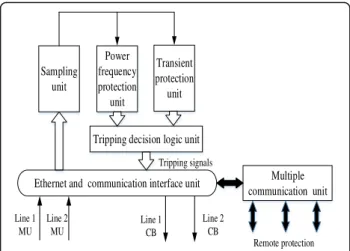
The design of integrated protection is shown in Fig. 13. The sampling unit of power frequency and transient protection adopts the integrated design. The input sig-nals of sampling unit are from the process bay equip-ment, communicated by Ethernet and communication interface unit.
Power frequency protection unit and transient protec-tion unit work respectively, and transfer their results into the tripping decision logic unit. The tripping deci-sion logic unit coordinates the outputs of two protec-tions and decides the final tripping signals, and trips the corresponding circuit breaker. In addition, the integrated protection can communicate with other remote protec-tion by multiple communicaprotec-tion unit.
Conclusion
A new integrated protection principle based on multi-frequency domain information is proposed to solve the protection problems of UHV half-wavelength AC trans-mission line. Fault transient characteristics of half-wavelength AC transmission is quite different from the characteristics of the normal transmission line. The inte-grated protection proposed in this paper can improve the protection performances of the half-wavelength AC transmission line. The essential benefits are shown as follow,
1) To protect the full line of the half-wavelength AC transmission line for different fault types;
2) To improve reliability and sensitivity;
3) To implement high speed protection for full line;
4)To avoid the time delay caused by communication and transient process.
Authors’contributions
QW carried out the system design, participated in the simulation analysis and drafted the manuscript. ZB participated in the design of the study and coordination. XM and MZ carried out the simulation and helped to draft the manuscript. YZ, YZ and LW participated in its design and coordination and helped to perform the statistical analysis. All authors read and approved the final manuscript.
Competing interests
The authors declare that they have no competing interests.
Received: 17 June 2016 Accepted: 15 November 2016
References
1. Zheng, J. C. (2009). Smart power devices and half-wave-length AC transmission technology[J].Power and Electrical Engineers, 3, 12–15. 2. Qin, X. H., Zhang, Z. Q., Xu, Z. X., Zhang, D. X., & Zheng, J. C. (2011). Study
on the steady state characteristic and transient stability of UHV AC half-wave-length transmission system based on quasi-steady model[J]. Proceedings of the CSEE, 31(31), 66–75.
3. Portela, C., & Tavares, M. C. (2002).“Modeling simulation and optimization of transmission lines[C].”Applicability and limitations of some used procedures IEEE(pp. 1–38). Recife: IEEE.
4. Dias, R., Santos, G., & Aredes, M. (2005).“Analysis of a series tap for half-wavelength transmission lines using active filters[C].”IEEE 36th Power Electronics Specialists Conference(pp. 1894–1900). Recife: IEEE. 5. Sokolov, N. I., & Sokolova, R. N. (1999). The feasibility of using half-wave
power transmission lines at higher frequencies[J].Electrical Technology Russia, 1, 66–84.
6. Wang, G., Li, Q. M., & Zhang, L. (2010).“Research status and prospects of the half-wavelength transmission lines[C].”Power and Energy Engineering Conference(pp. 1–5). Chengdu: PEEC.
7. Xiao, S. W., Cheng, Y. J., & Wang, Y. (2011). A Bergeron model based current differential protection principle for UHV half-wavelength AC transmission line[J].Power System Technology, 35(9), 46–50.
8. Liu, J. H. (2013). Study on protection Principle for Half Wavelength AC Transmission Line Based on Distributed Parameters[D]. Beijing: North China Electric Power University.
9. Wang, Y. (2011). Research on longitudinal differential protection principle for half wavelength AC transmission line[D]. Beijing: North China Electric Power University.
10. Cheng, Y. J. (2012). Analysis of the fault and the relay protection for half wavelength AC transmission line[D]. Beijing: North China Electric Power University.
11. WOLF, A. A., & SHCHERBACHEV, O. V. (1940). On normal working conditions of compensated lines with half-wave characteristics (in Russian) [J]. Elektrichestvo, 1, 147–158.
12. Fang, Y. (2013). Research on half wave-length AC transmission line protection principle[J].Science & Technology Information, 5, 390–392. 13. Li, B., He, J. L., Yang, et al. (2007). Improvement of distance protection
algorithm of UHV long transmission line[J].Automation of Electric Power Systems, 31(1), 43–46.
14. Li, B., He, J. L., Chang, W. H., et al. (2010). Bergeron model based distance protection for long transmission lines[J].Automation of Electric Power Systems, 34(23), 52–55.
15. Duan, J. D., Zhang, B. H., Li, P., et al. (2007). Principle and algorithm of non-unit transient-based protection for EHV transmission lines[J].Proceedings of the CSEE, 27(7), 45–51.
16. Zhang, W. J., He, B. T., & Shen, B. (2007). Traveling-wave differential protection on UHV transmission line with shunt reactor[J].Proceedings of the CSEE, 27(10), 56–61.
Ethernet and communication interface unit
Line 1 MU Line 2 MU Line 1 CB Line 2 CB Multiple communication unit Sampling unit Power frequency protection unit Transient protection unit
Tripping decision logic unit
Tripping signals
Remote protection