Rectangular Microstrip Patch Antenna Arrays With Inset for Cellular Phones
Application
Adnan M. Affandi , Abdullah M Dobaie, Navin Kasim, Nawaf A. Al-Zahrani Electrical and Computer Engineering
King Abdulaziz University Jeddah, Saudi Arabia
ABSTRACT: In this paper, the microstrip line fed rectangular patch antenna with inset has been designed and simulated by
using ADS software in order to study the effects of various parameters on the antenna’s radiation characteristics. Also, two-by-two, four-by-four, eight-by-eight and sixteen-by-sixteen microstrip patch antenna arrays has been discussed. The effect on the antenna parameters due to increasing the antenna elements (array) is observed clearly on antenna gain, directivity. This type of antenna can be used for cellular phones application.
Keywords: Microstrip Antennas, Linear Polarization, Antenna Arrays, Corporate Feeding Networks, Cellular Phones
Received: 10 December 2014, Revised 11 January 2015, Accepted 17 January 2015
© 2015 DLINE. All Rights Reserved
1. Introduction
Microstrip patch antennas are increasing in popularity for use in wireless applications due to their low-profile structure. Therefore they are extremely compatible for embedded antennas in handheld wireless devices such as cellular phones, pagers etc... The telemetry and communication antennas on missiles need to be thin and conformal and are often Microstrip patch antennas. Another area where they have been used successfully is in cellular phones communication [1].
2. Antenna Design
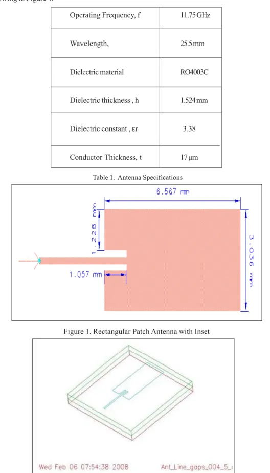
A rectangular patch antenna with inset has been designed[ in single layer of RO4003C dielectric material with dielectric constant, μr = 3.38. Table 1 shows the antenna specifications [1].
Figure 1 shows the rectangular patch antenna with inset dimensions along with single microstrip line feeding method.
Operating Frequency, f 11.75 GHz
Wavelength, 25.5 mm
Dielectric material RO4003C
Dielectric thickness , h 1.524 mm
Dielectric constant , εr 3.38
Conductor Thickness, t 17 μm
Table 1. Antenna Specifications
Figure 1. Rectangular Patch Antenna with Inset
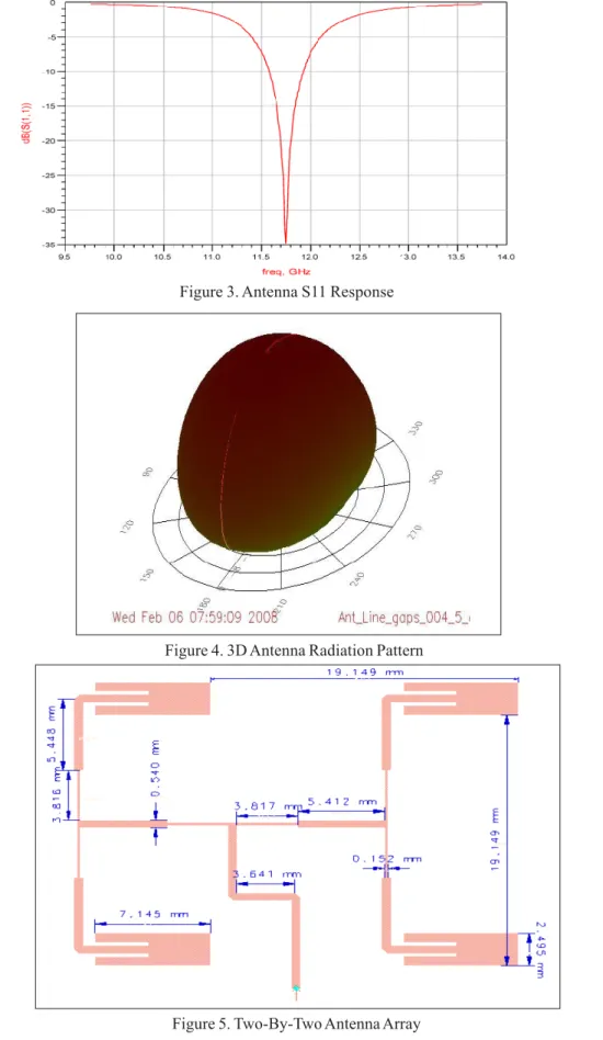
Figure 3. Antenna S11 Response
Figure 4. 3D Antenna Radiation Pattern
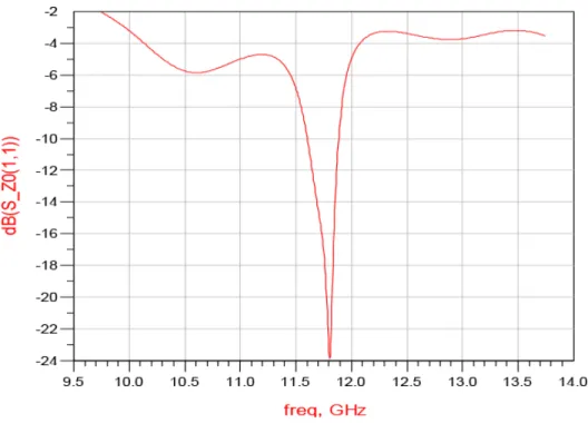
3. Two-by-two Antenna Array
This design is used as an element to generate a 2x2 array in order to improve the antenna efficiency, directivity and gain for the radiating system. The 2x2 rectangular patch antenna with inset array is shown in the Figure 5 [2].
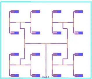
S11 response of the antenna and radiation pattern are showing in Figures 6 and 7 respectively.
Figure 10. 3D Antenna Radiation Pattern of 4x4 Antenna Array Figure 9. S11 Response of 4x4 Antenna Array
4. Four-by-four Antenna Array
Further design is used as an element to generate a 4x4 array in order to improve more the antenna efficiency, directivity and gain for the radiating system. The 4x4 rectangular patch antenna with inset array is shown in the Figure 8.
Figure 13. 3D Antenna Radiation Pattern of 16x16 Antenna Array Figure 12. Sixteen-By-Sixteen Antenna Array
Figure 11. 8×8 Antenna Array 5. Eight-by- Eight Antenna Array
6. Sixteen-by-Sixteen Patch Antenna Array
The largest level of antenna array designed is sixteen by sixteen elements to get the best possible improvement of antenna parameters. The 8x8 rectangular patch antenna with inset array is shown in the Figure 12.
The antenna gain increased up to 24.01 dB with the dual bandwidth = 300 MHz.
The antenna radiation pattern is shown in Figures 13.
7. Simulation Results Discussion
From comparison results summary Table 2, we can observed clearly the improvement in the antenna gain as well as directivity by using the antenna arrays and increasing the size of the arrays up to 16x16 arrays and improvement is around 314%. However, there is no effect on the bandwidth although the return loss is increased. Linear polarization is obtained from this kind of antenna and phase shift has been occurred too.
Furthermore, we got dual bandwidth in 16x16 antenna arrays which can be utilize in different frequency bands applications such as Direct Broadcast satellite and cellular phones communication.
8. Conclusion
In this paper, a new microstrip antenna element and its integration into 2-by-2, 4-by-4, 8-by-8 and 16-by-16 planar array are introduced. This array can be used in cellular phones application. The proposed element consists of only one single dielectric material with two metal layers, which makes it cheaper than other elements of more layers usually used for this application.
Acknowledgments
The authors acknowledge Engineering Faculty in King AbdulAziz University (KAU), Saudi Arabia, for supporting the research work
References
[1] Balanis., Constantine. (1997). Antenna theory-Analysis and Design, John Wiley & Sons Ltd, Reprinted.
[2] Al-Harbi, Samir., Al-Sayed, Ahmad., Al-Grani, Othman. (2008). Design and Optimization of Multilayer Microstrip Antennas, KAU, Bacholer Thesis, p. 5-31.
[3] Gao, S, C., Li, L, W., Yeo, T, S., Leong, M, S. (2001). A dual frequency Compact Microstrip patch Antenna , Radio Science, 36 (6) 1669-1682. Nov-Dec.
[4] IEEE AEROSPACE AND ELECTRONIC SYSTEM, March 2007.
[5] Saunders, Simon R. (2003). Antennas and Propagation for Wireless Communication Systems, John Wiley & Sons Ltd., October.