THE MORPHOLOGICAL PYRAMID AND ITS APPLICATIONS TO
REMOTE SENSING: MULTIRESOLUTION DATA ANALYSIS AND
FEATURES EXTRACTION
L
APORTERIEF
LORENCE1,2, F
LOUZATG
UY2 ANDA
MRAMO
LIVIER31
CESBIO, 18 avenue Edouard Belin 31401 Toulouse cedex 4, France, 2ENSAE, 10 avenue Edouard Belin 31055 Toulouse, France, 3Université Paul Sabatier, Mission Formation Continue et Apprentissage, 118 route de Narbonne, 31062 Toulouse, France
e-mail: [email protected], [email protected], [email protected] (Accepted February 16, 2002)
ABSTRACT
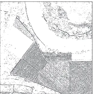
In remote sensing, sensorsare more and more numerous, and their spatial resolution is higher and higher. Thus, the availability of a quick and accurate characterisation of the increasing amount of data is now a quite important issue. This paper deals with an approach combining a pyramidal algorithm and mathematical morphology to study the physiographic characteristics of terrestrial ecosystems. Our pyramidal strategy involves first morphological filters, then extraction at each level of resolution of well-known landscapes features. The approach is applied to a digitised aerial photograph representing an heterogeneous landscape of orchards and forests along the Garonne river (France). This example, simulating very high spatial resolution imagery, highlights the influence of the parameters of the pyramid according to the spatial properties of the studied patterns. It is shown that, the morphological pyramid approach is a promising attempt for multi-level features extraction by modelling geometrical relevant parameters.
Keywords: mathematical morphology, multiresolution analysis, pyramid algorithms, remote sensing.
INTRODUCTION
Aerial and satellite data provide information about large areas. Satellite image resolution is usually coarser than aerial resolution, even if the difference is about to be filled in. Metric satellite data give access to a wider range of object sizes for a more accurate survey of land surfaces and create new challenges that we propose to address using here numerical aerial images simulating high resolution satellite data. In order to detect and extract the corresponding multiresolution components of these images, we propose a pyramid multiresolution analysis based on mathematical morphology. The paper begins with a review of pyramid algorithms followed by the description of the morphological pyramid. An application is last presented using object reconstructions at several levels of the pyramid.
THE MORPHOLOGICAL PYRAMID
Background and review
The concept of the pyramid, due to Tanimoto and Pavlidis (1975), was further developed by Marr (1982) in the field of vision and by Mallat (1989) in
the context of Multi Resolution Analysis. Then, the number of different pyramids increased along with the diversity of their applications. In this respect, it is difficult to give a universal definition of the pyramid concept. However, two definitions have been proposed by Eichmann et al. (1988) and Goutsias and Heijmans (2000): “1) The pyramid consists of a (finite or infinite) number of levels such that the information content decreases toward higher levels and 2), each step toward a higher level is implemented by an (information-reducing) analysis operator, whereas each step toward a lower level is implemented by an (information-preserving) synthesis operator.” Pyramid algorithms have been used in numerous applications such as compression, objects segmentation or features extraction (Mallat, 1989). A
more complete account of those methods can be
found in Lindenberg (1994).
There are several advantages to combining pyramidal algorithms and mathematical morphology.
First of all, multiresolution analysis enables the decomposition of a landscape into a set of landscapes at different spatial resolutions. This point is crucial because it is related to the concept of overlapped elements that are significant at several scales. Applying a morphological filter, or more generally a non linear one, at all those resolutions enables to characterise landscape objects by their geometrical features. Next, the property of idempotence of the morphological filter ensures the extraction of all features at a given scale with only one application. Finally, this type of filter enables the differentiation of clear elements on a dark background from dark ones on a clear background, which is very significant for reflectance measurements interpretation in remote sensing imagery.
In that case, the extraction of the local reflectance variations is performed by local comparison. It is consequently robust whatever the radiometric quality of the image.
At each level of the pyramid, the extracted information describes image characteristic patterns and can be used also for the reconstruction of isolated objects.
The morphological pyramid algorithm
The scheme of our pyramid algorithm is performed by the recursive application of a basic process made up of the following operations (Fig. 1) (Laporterie et al., 2000; Flouzat et al., 2001):
1. morphological filtering,
2. computation of the difference (initial image -filtered image),
3. sampling.
Those operations are iterated, with every iteration yielding a level of the pyramid. Thus, at level i, mathematically, the transformations are:
1. IFi = MT(Ii) (1)
where MT represents the Morphological Transform and IFi the filtered image at level i.
The step 1 performs the filtering of the image. This low-pass filter is composed of combinations of opening and closing.
The objects extracted are characterised in terms of level of reflectance. For instance, beginning the process by an opening (respectively a closing) may favour the extraction of clear (respectively dark) components. Consequently, the non-linear filter is chosen to correspond with the geometry of the extracted features.
The structuring element (SE) defines the size and shape of the neighbourhood on which the filter is applied, and accordingly the size and shape of the objects extracted at the level i. The choice of the SE is crucial for directional structure extraction and is based on the morphological properties of the patterns of interest. So, according to the SE, the extracted objects will have a priori known size, shape and orientation that are meaningful at a given scale.
2. Dsup, filter, i = sup(Ii,IFi) - IFi and
Dinf, filter, i = sup(Ii,IFi) - Ii (2)
where Dsup, filter, i and Dinf, filter, i represents the details (non
linear equivalent of high frequencies) at the level i.
The second step consists in evaluating the information extracted at step 1. The characterisation of the extracted structures enables the analysis of the image. Dsup, filter, i represents clear structures on dark
background whereas Dinf, filter, i represents dark structures
on clear background at level i. If MT is an opening (resp. a closing), IFi≤ Ii (resp Ii≤ IFi) then Dinf, filter, i = 0
(resp. Dsup, filter, i = 0). Consequently, Dsup, filter, i is a
clear (resp. dark) top hat. Otherwise, neither Dinf, filter, i
nor Dsup, filter, i are ‘empty’ images nor correspond to top
hats. From a general point of view, any morphological filters (Serra, 1988) can separate details as done in the Dsup and the Dinf images". The choice of the
morphological filter depends on the objective.
Consequently, at each level, we are able to characterise two kinds of structures. The non-linearity of the filter induces a physical characterisation of objects. It preserves the most important property at this step, the different repartition of details (i.e. landscape components) between the Dsup and Dinf
images which corresponds to a realistic description of the landscape.
3. Ii+1 = sampling(IFi) (3)
Step 3 is the sampling which permits the
progression in the levels of the pyramid and characterises the resolution change from one level to the next. The sampling ratio is crucial as it determines the transition into the resolution space and leads to the multiresolution analysis. Thus, the resolution and size of the extracted elements can be chosen at each level of the pyramid. The choice of both size and sampling algorithm is important, since the size defines the resolution ratio between two consecutive levels and the dyadic sampling allows to reduce continuously successive images resolutions.
The process begins thus at the 0-level, where I0 is
I0 I1 ... Ii Ii+1 ...
Image Ii
Image IFi
Image Ii+1 Morphological Transform (step 1)
Sampling (step 3)
Difference (step 2)
Dsup,filter,i
Dinf,filter,i
Int. Ii+1,int Difference
Dsup,sampling,i
Dinf,sampling,i
-(Optional Step 4)
IRi+1
+ Dsup, sampling, i - Dinf, sampling, i
Interpolation IRFi
IRi
+ Dsup, filter, i - Dinf, filter, i
IR0 IR1 ... IRi IRi+1 ...
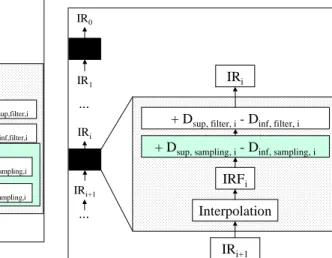
Fig. 1. Morphological pyramid decomposition flowchart. Fig. 2. Morphological pyramid reconstruction flowchart.
4. An inverse transformation can be performed (Fig. 2) allowing the reconstruction of the initial image. The necessary additional step concerns the calculation of the information lost at the sampling step and requires the computation of the difference (filtered image - sampled image).
This step is mathematically expressed by:
Dsup, sampling,i = sup(IFi, interpolation(Ii+1))
– interpolation(Ii+1) (4)
and
Dinf, sampling,i = sup(IFi, interpolation(Ii+1)) - IFi (5)
where interpolation(Ii+1) is the interpolation of Ii+1 to
the size of IFi, and thus at the size of images at the
level i of the pyramid.
The set of details are calculated by:
sup, , inf, ,
sup, , inf, ,
1
1
interpolation( )
interpolation( )
i filter i filter i
sampling i sampling i
i i i i
i i
D D D
D D
I IF IF I
I I + + = − + + − = − + − = − (6)
Let N be the number of levels performed. The reconstruction begins with:
1 1
1 1
interpolation( )
= interpolation( )
interpolation( )
N N N
N
N N N
IR I D
I
I I I
− − − − = + + + − = (7)
Then, the reconstruction is performed by (cf. fig. 2):
i i i
interpolat
ion
IR
D
IR
−1=
(
)
+
(8)Using a recursive loop,
1
1
interpolation( )
i i i
i
IR I D
I
−
−
= +
= (9)
Finally,
IR
0=
I
0, and the inverse transform is exact.In the following, Dsup, i (resp. Dinf, i) represents
Dsup, filter, i (resp. Dinf, filter, i).
If the pattern characteristics of the observed objects in the spatial domain are a priori known, we can determine a suitable parameterisation of the morphological pyramid to compute object extraction. Consequently, the choices of the filter, the structuring element, and the sampling ratio, determine the shape, size and orientation of the extracted objects. Whatever the components of the image, the characterisation of a structured image can be done the same way. This methodology is therefore physically determined by the knowledge of the spatial characteristics of the searched features. Once extracted, these features can be treated if necessary as markers, as shown in the following paragraph.
APPLICATION TO FEATURES
EXTRACTION IN REMOTE SENSING
extracted at different resolutions. In all cases, a filter is chosen to be symmetric between opening and closing not to favour either clear or dark structures.
Mathematically, it can be expressed by ( )
2 ) ( 2 1
I F 1 I
O + ,
where O(I) and F(I) are the opening and closing of the image I.
In Fig. 3, orchards show a high contrast compared to soils and an almost equivalent frequency. Consequently, the first level of details (Dsup, 0 and Dinf, 0)
extracts tree lines and fields borders corresponding to the first structural and textural level. For example, Fig. 4 is Dsup, 0, obtained by a 1-radius SE and binarised.
Of course, characterising accurately a component requires further processing, and the Dsup and Dinf
images must then be treated as markers. For instance, a threshold is applied to Dsup, 0 and is thus binarised.
Then, the marker obtained this way is used to select the corresponding area within the initial image. Finally, a conditional dilation of the marker into the initial image is performed. This reconstruction is done through the marker propagation through two steps: i) extraction of some pixels by intersection with the initial image, ii) propagation of this set of pixels until the selected pixels values are lower than the values of their neighbours. The result is shown in Fig. 5 where field borders are separated from field furrows in a binary representation.
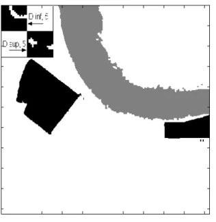
In the last levels of the pyramid, Fig. 6 illustrates the effect of a decreased resolution obtained after the fifth level. This figure represents Dsup, 5 and Dinf, 5
after two reconstructions. The computation of the fifth level of the pyramid is crucial for the extraction of bare soil fields and river markers. After binarisation, the bare soil field markers appear in the Dsup, 5 details because its reflectance is higher than
most of the landscape elements in the neighbourhood. The river marker is contained in the Dinf, 5 because
water absorption of solar incident radiation is higher than in the neighbouring elements. The small squares in Fig. 6 show the markers. The reconstruction process can be summarised as: i) over sampling of the detail image to the size of the initial image, ii) binarisation of the resulting image to determine the markers, iii) selection of the marker areas in the initial image, iv) conditional dilation of these markers into the initial image. This reconstruction is done by the marker propagation inside a boundary corresponding to a local variability of the signal lower than a given threshold. This threshold is chosen to be equal to the local standard deviation of the values of the image in the neighbourhoods of the propagating pixel. Such parameterisation is justified at the lowest levels of the pyramid because the markers refer to large and homogeneous objects. The result shown in Fig. 6 represents the open fields in black and the river in grey.
Fig. 5. Green band Dsup,0, after reconstruction. Fig. 6. Green band Dsup,5, and Dinf, 5 after reconstruction.
CONCLUSION
This method enables the extraction of objects from images. This kind of extraction is determined by the physical properties of the objects and modelled by the parameters of the pyramid. Even if Dsup or Dinf do
not characterise objects by themselves, further simple processing enables their characterisation. In most cases, one class of patterns is not exactly extracted at a given level, and details must be generally considered as markers for the objects of interest.
The morphological pyramid decomposition enables a kind of band-pass filtering explicitly performed in the image domain and extracts elements according to their sizes.
REFERENCES
Eichmann G, Lu C, Zhu J, Li Y (1988). Pyramidal Image Processing using morphology, Applications of digital image processing XI. Proceedings of the SPIE, 974:30-7.
Flouzat G, Amram O, Laporterie F, Cherchali S (2001). Multiresolution analysis and reconstruction by a morphological pyramid in the remote sensing of terrestrial surfaces. Signal Processing 81(10):2171-85. Goutsias J, Heijmans H (2000). Non Linear multiresolution
signal decomposition schemes - Part I: Morphological pyramids. IEEE Transactions on image processing 9(11):1862-76.
Laporterie F, Amram O, Flouzat G, Pilich E, Gay M (2000). Data fusion thanks to an improved morphological pyramid approach: comparison loop on simulated images and application to SPOT 4 data. IEEE/IGARSS’00. Lindeberg T (1994). Scale-space theory: a basic tool for
analysing structures at different scales, in Advances in Appl. Stat., Statistics and Images:2, chap. 11, 225-270, K. V. Mardia ed., a supplement to Journ. of Appl. Stat. 21(1/2).
Mallat S (1989). A theory for multiresolution signal decomposition: the wavelet representation. IEEE Trans. on PAMI 11(7):674-93.
Marr D (1982). Vision, a computational investigation into the human representation and processing of visual representation. Freeman.
Pohl C, Van Genderen G (1998). Multisensor image fusion in remote sensing: concepts, methods and applications. International Journal of Remote Sensing 19(5):823-54. Rosenfeld A (1982). Some useful properties of pyramids.
Multiresolution Symposium 2-5.
Serra J (1988). Image analysis and mathematical morphology V2: theoretical advances. Academic Press.
Serra J, Salembier P. (1993). Connected operators and pyramids. Proc. of SPIE Conf. on Visual communication and image processing, SPIE, 2030:65-76.
Tanimoto S, Pavlidis T (1975). A hierarchical data structure for image processing. Computer Graphics and Images Processing 4(2):104-19.