A Novel Three-Port Converters For Solar Power System
B.Surendra1, B.Srinivasulu, SK.Meera shareef2,
1PG Scholar,2Asst. Prof. ,3Asst. Prof. , Dept. Of EEE ,Prakasam Engineering College, JNTUK,India,
[email protected]; [email protected]; [email protected]
Abstract: The conventional three-port power converters with bridge rectifiers are inefficient and may not be practical for the low-voltage micro generators. This paper presents an efficient ac-to-dc power converter that avoids the bridge rectification and directly converts the low ac input voltage to the required high dc output voltage at a higher efficiency. The proposed converter consists of a boost converter in parallel with a buck– boost converter, which are operated in the positive half cycle and negative half cycle, respectively. Detailed analysis of the converter is carried out to obtain relations between the power, circuit parameters, and duty cycle of the converter. Based on the analysis, control schemes are proposed to operate the converter. Design guidelines are presented for selecting the converter component and control parameters. A self-starting circuit is proposed for independent operation of the converter. Detailed loss calculation of the converter is carried out. Simulation results are presented to validate the proposed converter topology and control schemes. Keywords: AC–DC conversion, boost converter, energy harvesting, low power, low voltage, power converter control.
Introduction: The future of this earth and mankind substantially depends on our ability to slow down the population increase in the “Third World” by civilized means. The key is to increase the standard of living, to overcome the inhumane poverty and deprivation. Development requires mechanization and energy. Energy consumption increases proportionally to the gross national product or prosperity while simultaneously the population growth will decrease exponentially. Many developing countries possess hardly any energy sources and their population doubles every 15- 30 years. The result of which are commonly known that is civil wars and
fundamentalism. If these developing countries are provided with only a humane and viable minimum of energy the global energy consumption will drastically increase. The sun is the only source which can supply such an enormous amount of energy without an ecological breakdown and without safety hazards and without a rapid depletion of natural resources at the expenses of future generations. Solar chimneys are such devices which can generate energy up to large extent by use of the simple device that is greenhouse collector, Vertical chimney and turbine and produce electricity continuously at minimum cost. It is very necessary to adopt this technology in every part of the world like other conventional sources which we are using regularly.
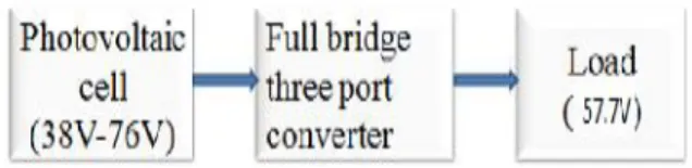
Figure 1: Block Diagram
input source and energy storage element is a step-up or step-down converter With limited voltage conversion ratio, they are not flexible enough for applications where the voltage of the source port, such as solar, fuel cells and thermoelectricgenerator, varies over a wide range. We focus on full bridge three port converter which is buck boost integrated for both Buck and boost operations. It uses fewer components thereby achieves higher system efficiency.
A three port converter must features single-stage conversion between any two of the three ports, higher system efficiency, fewer components, faster response, compact packaging, and unified power management among the ports with centralized control. For renewable energy harvesting systems, one of the toughest challenges for the power management circuits is that, the converter must be able to efficiently function witch all egging wide source voltage conditions. This motivates the need of buck-boost integrated full bridge three port converters with wide input voltage range, higher system efficiency, and small physical size. ZVS of all the primary side
Switches can also be achieved with this FB-TPC. 2. Derivation OF the FB-TPC From a Full-Bridge DC-DC Converter
A systematic method for generating Three Port Converter topologies from Full Bridge Converters are described here. This systematic method is used to find a novel full bridge TPC(FB-TPC). This method splits the two switching legs of the FBC into two switching cells with different sources and allows a dc bias current in the transformer. A buck boost converter is integrated in the FB-TPC and used to configure the power flow path between the two ports on the primary side of the converter, which is aimed to handle a wide range of source voltage. ZVS of all the primary-side switches can also be achieved with this FB-TPC.
Referring to Fig.2, the primary side of the FBC consists of two switching legs, composed of SA1 , SA2 and SB1 , SB2 in parallel, connected to a common input source Vs. For the primary side of the FBC, the constraint condition of the operation of the FBC is the voltage-second balance principle of the magnetizing inductor Lm. This means that, from a topological point of view, the two switching legs of the FBC can also be split into two symmetrical parts, cells A and B, if only Lm satisfies the voltage-second balance principle, as shown in Fig.3.
The two cells can be connected to different sources, Vsa &V sb respectively, as shown in Fig.4, and then a novel FB-TPC is derived. The voltage of the two sources of the FB-TPC cans be arbitrary. Specially, if Vsa always equals V sb , the two cells can be paralleled directly and then the conventional FBC is derived. Therefore, the FBC can be seen as a special case of the FB-TPC as shown in Fig.4.
Vsa and Vsb freely. The unique characteristics of the FB-TPC are analyzed and summarized as follows. 1) The FB-TPC has two bidirectional ports and one isolated output port. Single-stage power conversion between any two of the three ports is achieved. The FB-TPC is suitable for renewable power systems and can be connected within input source and an energy storage element, such as the photovoltaic (PV) with a battery backup or with two energy storage elements, such as the hybrid battery and the super capacitor power system.
2) A buck-boost converter is integrated in the primary side of the FB-TPC. With the integrated converter, the source voltage Vsa can be either higher or lower than Vsb advice versa. This indicates that the converter allows the sources voltage varies over a wide range.
3) The devices of the FB-TPC are the same as the FBC and no additional devices are introduced which means high integration is achieved.
4) All four active switches in the primary side of the FBTPC can be operated with ZVS by utilizing the energy stored in the leakage inductor of the transformer, who seprinciple is similar to the phase-shift FBC.
3. FB-TPC for the Stand-Alone Renewable Power System
The FB-TPC, as shown in Fig.3, is applied to a stand-alone PV power system with battery backup to verify the topology. To better analyze the operation principle, the FB-TPC topology is redrawn in Fig.5, the two source ports are connected to a PV source and a battery respectively, while the output port is connected to a load.
There are three power flows in the standalone PV power system 1) from PV to load 2) from PV to battery and 3) from battery to load. As for the FB-TPC, the load port usually has to be tightly regulated to meet the load requirements, while the input port from the PV source should implement the maximum power tracking to harvest the most energy. Therefore, the mismatch in power between the PV source and load has to be charged into or discharged from the battery port, which means that in the
FB-TPC, two of the three ports should be controlled independently and the third one used for power balance. As a result, two independently controlled variables are necessary
A. Switching state analysisIgnoring the power loss in the conversion, we have
Ppv=pb+po
Where ppv, pb,and poare the power flows through the
PV,battery and load port, respectively. The FB-TPC has three possible operation modes 1) dual-output (DO) mode, with ppv≥ po the battery absorbs the
surplus solar power and both the load and battery take the power from PV (2) dual-input (DI)mode with ppv≤ poand ppv> po , the battery discharges to
feed the load along with the PV and (3) single-input single-output(SISO) mode with ppv = 0, the battery supplies the load power alone. When ppv= 0 exactly,
the solar supplies the load power alone and the converter operate in a boundary state of DI and DO modes. This state can either be treated as DI or` DO mode. Since the FB-TPC has a symmetrical structure, the operation of the converter in this state is the same as that of SISO mode, where the battery feeds the load alone. The operation modes and power flows of the converter are listed in Table I. The power flow paths/directions of each operation mode have been illustrated in Fig.6.The switching states in different operation modes are the same and the difference between these modes are the value and direction of
iLm as shown in Fig.5, which is dependent on the
Table 1: Operation Modes of the FB-TPC
Operation modes
Power of
PV Power of battery
Dual-output mode
Ppv>po Battery
charging,pb≥0
Dual-input mode
Ppv<po,
Ppv>o
Battery discharging,pb<o
Single-input single-output
mode
Ppv=o Battery discharging,
Pb=po
In the DO mode, iLmis positive, in the SISO mode, iLm
is negative and in the DI mode, iLm can either be
positive or negative. Take the DO mode as an example to analyse.
For simplicity, the following assumptions are made: 1) Cpv, Cband Co are large enough and the
voltages of the three ports,Vpv, Vband Vo are constant
during the steady state and 2) theVpv ≥ Vb case is
taken as an example for the switching state analysis.
There are four switching states in one switching cycle. Thekey waveforms are shown in Fig.11.
State I [ 0 t - 1 t ]
Before t0, SA2and SB2 are ON and SA1 and SB1 are
OFF, while iLmfreewheels through SA2and SB2. At t0
, SA1turns ON and SA2turns OFF. A positive voltage
is applied across the transformer’s primary winding
State II [ 1 t - 2 t ]
State III [ 2 t - 3 t ]
At t2, SA1 turns OFF and SA2 turns ON. A negative voltage is applied on the primary winding of the transformer
At t3, SB1 turns OFF and SB2 turns ON. The voltage across the primary winding is clamped at zero and iLm
freewheels through SA2 and SB2.
4. Simulation Results
Full bridge three port converter is simulated usingMATLAB/SIMULINK. Simulink model of the Full Bridge Three Port Converter operating in dual output mode is shown in Fig.12.Simulation of the full bridge three port converter operating in dual output mode is done by using 38V DC from PV array as input. A regulated voltage, 57.7V DC is obtained at the output side. The magnetizing inductor of the transformer performs buck operation. In closed loop system, the output will be feedback through the controller to the input. Carrier based PWM is used for the closed loop operation. Here R load is used as the load in the closed loop circuit. Hence if there is any over distortion or variation in results, the PWM technique will given the feedback to input according input varied. It gives better result compared to the open loop R load, because of stable result.
Fig.12 Proposed model
voltage, current and power of theconverter are 42V, 4.3A and180W respectively.
Input Voltage Vin = 38V DC
Output voltage Vout = 57.7V
Output power
5. Conclusion
A Full-bridge converter generated with Three-port Fullbridgeshas been presented in this paper. A carrier basedPWM control method is applied to the Three-port Full-bridge converter. This converters offer the advantages of simple topologies and control, reduced number of devices and a Single-stage power conversion between any two of the three ports. They are suitable for renewable power systems that are sourced by solar, thermoelectric generator etc with voltages varying over a wide range. Full bridge three port converter is simulated using MATLAB/SIMULINK validating the effectiveness of the converter and its control scheme. A 57.7VDC constant output is obtained for input voltage range 38V DC.
References
[1] W. Jiang and B. Fahimi, “Multi-port power electric interface for renewable energy sources,” in
Proc. IEEEAppl. Power Electron. Conf., 2009, pp.
347–352.
[2] W. Jiang and B. Fahimi, “Multiport power electronic interface—Concept, modeling and design,”
IEEE Trans.Power Electron., vol. 26, no. 7,pp. 1890– 1900, Jul. 2011.
[3] H. Tao, J. L. Duarte, and M. A. M. Hendrix, “Multiport converters for hybrid power sources,”
IEEE Proc. Power Electron. Spec. Conf., pp. 3412– 3418, 2008.
[4] H. Tao, A. Kotsopulos, J. L. Duarte, and M. A. M.Hendrix, “Family of multiport bidirectional dc-dcconverters,” Inst. Electr. Eng. Proc. Elect. Power Appl.,vol. 153, no. 15, pp. 451–458, May 2006. [5] Z. Qian, O. Abdel-Rahman, H. Al-Atrash, and I.Batarseh, “Modeling and control of three-port DC/DCconverter interface for satellite applications,”
IEEETrans. Power Electron., vol. 25, no. 3, pp. 637– 649, Mar.2010.
[6] Z. Qian, O. Abdel-Rahman, H. Hu, and I. Batarseh, “Anintegrated threeport inverter for stand-alone PVapplications,”presented at the IEEE Energy Convers.Congr. Expo, Atlanta, GA,2010.
[7] H.Wu, R. Chen, J. Zhang, Y. Xing, H. Hu, and H. Ge, “Afamily of threeport half-bridge converters for a standalonerenewable power system,” IEEE Trans. PowerElectron., vol. 26, no.9,pp. 2697–2706, Sep. 2011.
[8] C. Zhao, S. D. Round, andW. Johann, “An isolated threeportbidirectional DC-DC converter with decoupledpower flow management,” IEEE Trans. Power Electron.,vol. 23, no. 5, pp. 24432453, Sep.
2008
[9] J. L. Duarte, M. A. M. Hendrix, and M. G. Simoes,“Three-port bidirectional converter for hybrid fuelcellsystems,”IEEE Trans. Power Electron., vol.