Free Range VHDL
Release: 1.21
Date: 4 January 2018
Book size: 160 mm by 240 mm Pages: 194
The electronic version of this book can be downloaded free of charge from:
http://www.freerangefactory.org
The authors have taken great care in the preparation of this book, but make no expressed or implied warranty of any kind and assume no responsibility for errors or omissions. No liability is assumed for incidental or consequential damages in connection with or arising out of the use of the information or programs contained in this book.
This book is licensed under the Creative Commons Attribution-ShareAlike Unported License, which permits unrestricted use, distribution, adaptation and reproduction in any medium, provided the original work is properly cited. If you build upon this work, you may distribute the resulting work only under the same, similar or a compatible license. To view a copy of this license, visit:
http://creativecommons.org/licenses/by-sa/3.0/
Feedback and Contribution
We are more than happy to consider your contribution in improving, extending or correcting any part of this book. For any communication or feedback that you might have about the content of this book you can contact the authors using the form at the following address:
http://www.freerangefactory.org
Table of Contents
Acknowledgments v
Purpose of this book 1
1 Introduction To VHDL 5
1.1 Golden Rules of VHDL 8
1.2 Tools Needed for VHDL Development 8
2 VHDL Invariants 11
2.1 Case Sensitivity 11
2.2 White Space 11
2.3 Comments 12
2.4 Parentheses 12
2.5 VHDL Statements 13
2.6 if,caseand loop Statements 13
2.7 Identifiers 14
2.8 Reserved Words 15
2.9 VHDL Coding Style 15
3 VHDL Design Units 17
3.1 Entity 18
3.3 Architecture 23
3.4 Signal and Variable Assignments 23
3.5 Summary 25
3.6 Exercises 26
4 VHDL Programming Paradigm 29
4.1 Concurrent Statements 30
4.2 Signal Assignment Operator “<=” 33
4.3 Concurrent Signal Assignment Statements 34
4.4 Conditional Signal Assignment when 38
4.5 Selected Signal Assignmentwith select 42
4.6 Process Statement 46
4.7 Summary 47
4.8 Exercises 48
5 Standard Models in VHDL Architectures 51
5.1 Data-flow Style Architecture 52
5.2 Behavioral Style Architecture 53
5.3 Process Statement 53
5.4 Sequential Statements 55
5.4.1 Signal Assignment Statement 57
5.4.2 ifStatement 57
5.4.3 caseStatement 62
5.5 Caveats Regarding Sequential Statements 66
5.6 Summary 67
5.7 Exercises: Behavioral Modeling 68
6 VHDL Operators 71
6.1 Logical Operators 72
6.2 Relational Operators 72
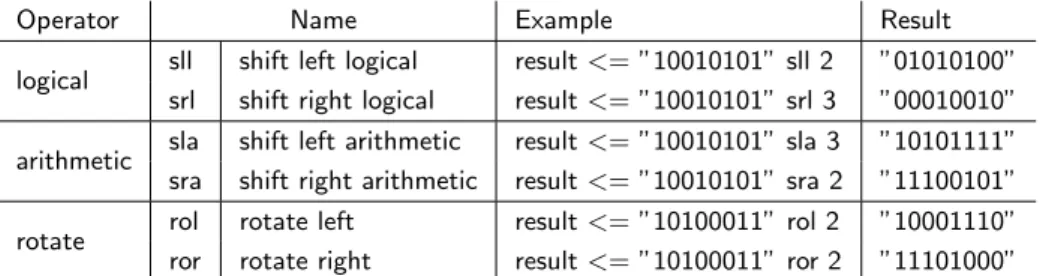
6.3 Shift Operator 72
6.4 Other Operators 73
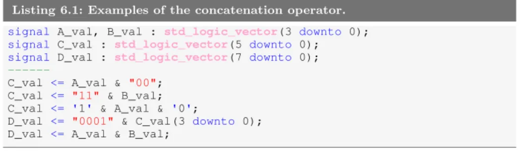
6.5 Concatenation Operator 74
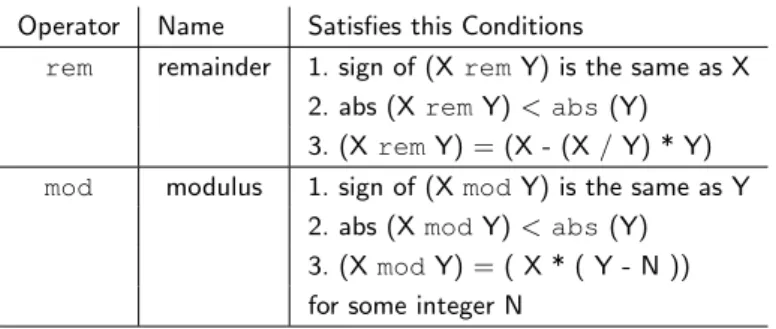
6.6 Modulus and Remainder Operators 74
iii
7 Using VHDL for Sequential Circuits 77
7.1 Simple Storage Elements Using VHDL 77
7.2 Inducing Memory: Data-flow vs. Behavioral Modeling 84
7.3 Important Points 85
7.4 Exercises: Basic Memory Elements 86
8 Finite State Machine Design Using VHDL 89
8.1 VHDL Behavioral Representation of FSMs 91
8.2 One-Hot Encoding for FSMs 101
8.3 Important Points 106
8.4 Exercises: Behavioral Modeling of FSMs 107
9 Structural Modeling In VHDL 119
9.1 VHDL Modularity with Components 121
9.2 Generic Map 129
9.3 Important Points 130
9.4 Exercises: Structural Modeling 131
10 Registers and Register Transfer Level 133
10.1 Important Points 140
10.2 Exercises: Register Transfer Level Circuits 140
11 Data Objects 143
11.1 Types of Data Objects 143
11.2 Data Object Declarations 144
11.3 Variables and Assignment Operator “:=” 145
11.4 Signals vs. Variables 145
11.5 Standard Data Types 147
11.6 User-Defined Types 147
11.7 Commonly Used Types 148
11.8 Integer Types 148
11.9 signedand unsignedTypes 150
11.10std logic Types 151
12 Looping Constructs 155
12.1 for and while Loops 155
12.1.1 for Loops 156
12.1.2 whileLoops 158
12.1.3 Loop Control:next and exit Statements 158
13 Standard Digital Circuits in VHDL 161
13.1 RET D Flip-flop - Behavioral Model 162
13.2 FET D Flipflop with Activelow Asynchronous Preset
-Behavioral Model 162
13.3 8-Bit Register with Load Enable - Behavioral Model 163 13.4 Synchronous Up/Down Counter - Behavioral Model 163 13.5 Shift Register with Synchronous Parallel Load - Behavioral
Model 164
13.6 8-Bit Comparator - Behavioral Model 165
13.7 BCD to 7-Segment Decoder - Data-Flow Model 165
13.8 4:1 Multiplexer - Behavioral Model 166
13.9 4:1 Multiplexer - Data-Flow Model 166
13.10 Decoder 167
Appendix A VHDL Reserved Words 169
Appendix B Standard VHDL Packages 171
B.1 IEEE Standard Libraries 173
B.2 Non-standard Libraries 173
Appendix C VHDL Reference Cards 175
Acknowledgments
Purpose of this book
subjects at hand.
The intent of this book is to present topics to someone familiar with digital logic design and with some skills in algorithmic programming languages such as Java or C. The information presented here is focused on giving a solid knowledge of the approach and function of VHDL. With a logical and intelligent introduction to basic VHDL concepts, you should be able to quickly and efficiently create useful VHDL code. In this way, you will see VHDL as a valuable design, simulation and test tool rather than another batch of throw-away technical knowledge encountered in some forgotten class or lab.
Lastly, VHDL is an extremely powerful tool. The more you understand as you study and work with VHDL, the more it will enhance your learning experience independently of your particular area of interest. It is well worth noting that VHDL and other similar hardware design languages are used to create most of the digital integrated circuits found in the various electronic gizmos that overwhelm our modern lives. The concept of using software to design hardware that is controlled by software will surely provide you with endless hours of contemplation. VHDL is a very exciting language and mastering it will allow you to implement systems capable of handling and processing in parallel ns-level logic events in a comfortable software environment.
This book was written with the intention of being freely available to everybody. The formatted electronic version of this book is available from the Internet. Any part of this book can be copied, distributed and modified in accordance with the conditions of its license.
3
1
Introduction To VHDL
VHDL has a rich and interesting history1. But since knowing this history is probably not going to help you write better VHDL code, it will only be briefly mentioned here. Consulting other, lengthier texts or search engines will provide more information for those who are interested. Regarding the VHDL acronym, the V is short for yet another acronym: VHSIC or Very High-Speed Integrated Circuit. The HDL stands for Hardware Description Language. Clearly, the state of technical affairs these days has done away with the need for nested acronyms. VHDL is a true computer language with the accompanying set of syntax and usage rules. But, as opposed to higher-level computer languages, VHDL is primarily used to describe hardware. The tendency for most people familiar with a higher-level computer language such as C or Java is to view VHDL as just another computer language. This is not altogether a bad approach if such a view facilitates the understanding and memorization of the language syntax and structure. The common mistake made by someone with this approach is to attempt to program in VHDL as they would program a higher-level computer language. Higher-level computer languages are sequential in nature; VHDL is not.
VHDL was invented to describe hardware and in fact VHDL is a con-current language. What this means is that, normally, VHDL instructions are all executed at the same time (concurrently), regardless of the size of
1
your implementation. Another way of looking at this is that higher-level computer languages are used to describe algorithms (sequential execution) and VHDL is used to describe hardware (parallel execution). This inherent difference should necessarily encourage you to re-think how you write your VHDL code. Attempts to write VHDL code with a high-level language style generally result in code that nobody understands. Moreover, the tools used to synthesize2 this type of code have a tendency to generate
circuits that generally do not work correctly and have bugs that are nearly impossible to trace. And if the circuit does actually work, it will most likely be inefficient due to the fact that the resulting hardware was unnecessarily large and overly complex. This problem is compounded as the size and complexity of your circuits becomes greater.
There are two primary purposes for hardware description languages such as VHDL. First, VHDL can be used to model digital circuits and systems. Although the word “model” is one of those overly used words in engineering, in this context it simply refers to a description of something that presents a certain level of detail. The nice thing about VHDL is that the level of detail is unambiguous due to the rich syntax rules associated with it. In other words, VHDL provides everything that is necessary in order to describe any digital circuit. Likewise, a digital circuit/system is any circuit that processes or stores digital information. Second, having some type of circuit model allows for the subsequent simulation and/or testing of the circuit. The VHDL model can also be translated into a form that can be used to generate actual working circuits. The VHDL model is magically3 interpreted by software tools in such a way as to create actual digital circuits in a process known assynthesis.
There are other logic languages available to model the behavior of digital circuit designs that are easy to use because they provide a graphical method to model circuits. For them, the tendency is to prefer the graphical approach because it has such a comfortable learning curve. But, as you can easily imagine, your growing knowledge of digital concepts is accompanied
2
Synthesis: the process of interpreting VHDL code and outputting a definition of the physical circuit implementation to be programmed on a device such as an FPGA.
3
7
by the ever-increasing complexity of digital circuits you are dealing with. The act of graphically connecting a bunch of lines on the computer screen quickly becomes tedious. The more intelligent approach to digital circuit design is to start with a system that is able to describe exactly how your digital circuit works (in other words, modeling it) without having to worry about the details of connecting large quantities of signal lines. Having a working knowledge of VHDL will provide you with the tools to model digital circuits in a much more intelligent manner.
Finally, you will be able to use your VHDL code to create actual func-tioning circuits. This allows you to implement relatively complex circuits in a relatively short period of time. The design methodology you will be using allows you to dedicate more time to designing your circuits and less time “constructing” them. The days of placing, wiring and troubleshooting multiple integrated circuits on a proto-board are gone.
VHDL is a very exciting language that can allow the design and imple-mentation of functions capable of processing an enormous amount of data by employing a relatively low-cost and low-power hardware. Moreover, what is really impressive is that, via simple VHDL modules, you can have direct access to basic ns-level logic events as well as communicate using a USB port or drive a VGA monitor to visualize graphics of modest complexity.
Modeling digital circuits with VHDL is a form of modern digital design distinct from schematic-based approaches. The programmer writes a loose description of what the final logic circuit should do and a language compiler, in this case called a synthesizer, attempts to “infer” what the actual final physical logic circuit should be. Novice programmers are not always able to convince the synthesizer to implement something that seems very clear in their minds. A somehow old-fashioned alternative to a descriptive language such as VHDL is one in which the programmer simply interconnects a finite number of digital blocks that he has pooled from a library in an attempt to reach the same objective. This approach is not only very time consuming but also inherently limiting and very error prone.
now is to learn how to properly use VHDL to describe what you want to implement.
1.1 Golden Rules of VHDL
Before you start, here are a couple of points that you should never forget when working with VHDL.
VHDL is a hardware-design language. Although most people have probably already been exposed to some type of higher-level computer language, these skills are only indirectly applicable to VHDL. When you are working with VHDL, you are not programming, you are “designing hardware”. Your VHDL code should reflect this fact. What does this mean? It means that unless you are inside certain constructs, your code lines will be executed almost all at once. If your VHDL code appears too similar to code of a higher-level computer language, it is probably bad VHDL code. This is vitally important.
Have a general concept of what your hardware should look like.
Although VHDL is vastly powerful, if you do not understand basic digital constructs, you will probably be unable to generate efficient digital circuits. Digital design is similar to higher-level language programming in that even the most complicated programming at any level can be broken down into some simple programming constructs. There is a strong analogy to digital design in that even the most complicated digital circuits can be described in terms of basic digital constructs. In other words, if you are not able to roughly envision the digital circuit you are trying to model in terms of basic digital circuits, you will probably misuse VHDL, thus angering the VHDL gods. VHDL is cool, but it is not as magical as it initially appears to be.
1.2 Tools Needed for VHDL Development
1.2 Tools Needed for VHDL Development 9
implementations. If you want to do VHDL coding for FPGAs you will have to play within the rules that current major FPGA manufacturers have drawn up to help you (rules which also ensure their continued existence in the market).
The successful implementation of a VHDL-based system roughly calls for the following steps: VHDL code writing, compiling, simulation and synthesis. All major FPGA manufacturers have a set of software and hardware tools that you can use to perform the mentioned steps. Most of these software tools are free of charge but are not open-source. Nevertheless, the same tools follow a license scheme, whereby paying a certain amount of money allows you to take advantage of sophisticated software features or get your hands on proprietary libraries with lots of components (e.g. a 32-bit processor) that you can easily include in your own project.
If your have no interest in proprietary libraries you can use open-source solutions (e.g. GHDL4 or BOOT5) which will allow you to compile and simulate your VHDL code using the open-source tool gcc6. At the time of writing, no open-source solution is available for the synthesis process. However synthesis can be accomplished using a free-license version of any major FPGA manufacturer’s software tool (e.g. Xilinx Vivado).
Thanks to the open-source community, you can write, compile and simulate VHDL systems using excellent open-source solutions. This book will show you how to get up and running with the VHDL language. For further tasks such as synthesis and upload of your code into an FPGA, the free of charge Xilinx Vivado7 or the Altera equivalent tool Quartus, can be employed.
4
VHDL simulator GHDL:http://ghdl.free.fr
5VHDL software tool BOOT:http://www.freerangefactory.org 6
Multi-language open-source compiler GCC:http://gcc.gnu.org
7
2
VHDL Invariants
There are several features of VHDL that you should know before moving forward. Although it is rarely a good idea for people to memorize anything, you should memorize the basic concepts presented in this section. This should help eliminate some of the drudgery involved in learning a new programming language and lay the foundation that will enable you to create visually pleasing and good VHDL source code.
2.1 Case Sensitivity
VHDL is not case sensitive. This means that the two statements shown in Listing 2.1 have the exact same meaning (don’t worry about what the statement actually means though). Keep in mind that Listing 2.1 shows an example of VHDL case sensitivity and not good VHDL coding practices.
Listing 2.1: An example of VHDL case insensitivity.
Dout <= A and B; doUt <= a AnD b;
2.2 White Space
VHDL is not sensitive to white space(spaces and tabs) in the source document. The two statements in Listing 2.2 have the exact same meaning. Once again, Listing 2.2 is not an example of good VHDL coding style. Note that Listing 2.2 once again indicates that VHDL is not case sensitive.
Listing 2.2: An example showing VHDL’s indifference to white space.
2.3 Comments
Comments in VHDL begin with the symbol “--” (two consecutive dashes). The VHDL synthesizer ignores anything after the two dashes and up to the end of the line in which the dashes appear. Listing 2.3 shows two types of commenting styles. Unfortunately, there are no block-style comments (comments that span multiple lines but do not require comment marks on
every line) available in VHDL.
Listing 2.3: Two typical uses of comments.
-- This next section of code is used to blah-blah
-- This type of comment is the best fake for block-style commenting.
PS_reg <= NS_reg; -- Assign next_state value to present_state
Appropriate use of comments increases both the readability and the understandability of VHDL code. The general rule is to comment any line or section of code that may not be clear to a reader of your code besides yourself. The only inappropriate use of a comment is to state something that is patently obvious. It is hard to imagine code that has too few comments so don’t be shy: use lots of comments. Research has shown that using lots of appropriate comments is actually a sign of high intelligence.
2.4 Parentheses
2.5 VHDL Statements 13
Listing 2.4: Example of parentheses that can improve clarity.
if x = '0' and y = '0' or z = '1' then
blah; -- some useful statement
blah; -- some useful statement
end if;
if ( ((x = '0') and (y = '0')) or (z = '1') ) then
blah; -- some useful statement
blah; -- some useful statement
end if;
2.5 VHDL Statements
Similar to other algorithmic computer languages, every VHDL statement is terminated with a semicolon. This fact helps when attempting to re-move compiling errors from your code since semicolons are often omitted during initial coding. The main challenge then is to know what constitutes a VHDL statement in order to know when to include semicolons. The VHDL synthesizer is not as forgiving as other languages when superfluous semicolons are placed in the source code.
2.6 if, case and loop Statements
As you will soon find out, the VHDL language contains if, case and
loop statements. A common source of frustration that occurs when learn-ing VHDL are the classic mistakes involvlearn-ing these statements. Always remember the rules stated below when writing or debugging your VHDL code and you will save yourself a lot of time. Make a note of this section as one you may want to read again once you have had a formal introduction to these particular statements.
Everyifstatement has a correspondingthen component
Eachifstatement is terminated with anend if;
If you need to use anelse ifconstruct, the VHDL version iselsif
Eachcase statement is terminated with anend case;
snippets (namely Gedit1). A good programmer distinguishes himself by other means than perfectly remembering code syntax.
2.7 Identifiers
An identifier refers to the name given to various items in VHDL. Examples of identifiers in higher-level languages include variable names and function names. Examples of identifiers in VHDL include variable names, signal names and port names (all of which will be discussed soon). Listed below are the hard and soft rules (i.e. you must follow them or you should follow them), regarding VHDL identifiers.
Identifiers should be self-describing. In other words, the text you apply to identifiers should provide information as to the use and purpose of the item the identifier represents.
Identifiers can be as long as you want (contain many characters). Shorter names make for better reading code, but longer names present more information. It is up to the programmer to choose a reasonable identifier length.
Identifiers can only contain a combination of letters (A-Z and a-z), digits (0-9) and the underscore character (“ ”).
Identifiers must start with an alphabetic character.
Identifiers must not end with an underscore and must never have two consecutive underscores.
The best identifier for a function that calculates the position of the Earth isCalcEarthPosition or calc earth position. Try to be consistent.
The best identifier for a variable that stores the age of your car is
AgeMyCarorage my car. Again, try to be consistent.
Remember, intelligent choices for identifiers make your VHDL code more readable, understandable and more impressive to coworkers, superiors, family and friends. A few examples of both good and bad choices for identifier names appear in Listing 2.5 and in Listing 2.6.
1
2.8 Reserved Words 15
Listing 2.5: Valid identifiers.
data_bus --descriptive name
WE --classic write enable
div_flag --real winner
port_A --provides some info
in_bus --input bus
clk --classic clock
clk_in clk_out mem_read_data
--Listing 2.6: Invalid identifiers.
3Bus_val -- begins with a number
DDD -- not self commenting
mid_$num -- illegal character
last__val-- consec. underscores
str_val_ -- ends with underscore
in -- uses VHDL reserved word
@#$%% -- total garbage
it_sucks -- try to avoid
Big_vAlUe-- valid but ugly
pa -- possibly lacks meaning
sim-val -- illegal character(dash)
DDE_SUX -- no comment
2.8 Reserved Words
There is a list of words that have been assigned special meaning by the VHDL language. These special words, usually referred to as reserved words, cannot be used as identifiers when writing VHDL code. A partial list of reserved words that you may be inclined to use appears in Listing 2.7. A complete list of reserved words appears in the Appendix. Notably missing from Listing 2.7 are standard operator names such as AND, OR, XOR, etc.
Listing 2.7: A short list of VHDL reserved words.
access after alias all attribute block
body buffer bus constant exit file
for function generic group in is
label loop mod new next null
of on open out range rem
return signal shared then to type
until use variable wait while with
2.9 VHDL Coding Style
identifiers and providing proper comments when and where necessary. Instead of stating here a bunch of rules for you to follow as to how your code should look, you should instead strive to simply make your source code readable. Listed below are a few thoughts on what makes readable source code.
Chances are that if your VHDL source code is readable to you, it will be readable to others who may need to peruse your document. These other people may include someone who is helping you get the code working properly, someone who is assigning a grade to your code, or someone who signs your paycheck at the end of the day. These are the people you want to please. These people are probably very busy and more than willing to make a superficial glance at your code. Nice looking code will slant such subjectivity in your favor.
If in doubt, your VHDL source code should be modeled after some other VHDL document that you find organized and readable. Any code you look at that is written down somewhere is most likely written by someone with more VHDL experience than a beginner such as yourself. Emulate the good parts of their style while on the path to creating an even more readable style.
Adopting a good coding style helps you write code without mistakes. As with other compilers you have experience with, you will find that the VHDL compiler does a great job of knowing a document has an error but a marginal job at telling you where or what the error is. Using a consistent coding style enables you to find errors both before compilation and after the compiler has found an error.
3
VHDL Design Units
The “black-box” approach to any type of design implies a hierarchical structure in which varying amounts of detail are available at each of the different levels of the hierarchy. In the black-box approach, units of action which share a similar purpose are grouped together and abstracted to a higher level. Once this is done, the module is referred to by its inherently more simple black-box representation rather than by the details of the circuitry that actually performs that functionality. This approach has two main advantages. First, it simplifies the design from a systems standpoint. Examining a circuit diagram containing appropriately named black boxes is much more understandable than staring at a circuit containing a countless number of logic gates. Second, the black-box approach allows for the reuse of previously written code.
architecture. Familiarity with the entity will hopefully aid in your learning of the techniques to describe the architecture.
3.1 Entity
The VHDL entity construct provides a method to abstract the functionality of a circuit description to a higher level. It provides a simple wrapper for the lower-level circuitry. This wrapper effectively describes how the black box interfaces with the outside world. Since VHDL describes digital circuits, the entity simply lists the various inputs and outputs of the underlying circuitry. In VHDL terms, the black box is described by an entity declaration. The syntax of the entity declaration is shown in Listing 3.1.
Listing 3.1: The entity declaration in VHDL. entity my_entity is
port(
port_name_1 : in std_logic ;
port_name_2 : out std_logic;
port_name_3 : inout std_logic ); --do not forget the semicolon
end my_entity; -- do not forget this semicolon either
my entity defines the name of the entity. The next section is nothing
more than the list of signals from the underlying circuit that are available to the outside world, which is why it is often referred to as an interface specification. The port name x is an identifier used to differentiate the various signals. The next keyword (the keyword in) specifies the direction of the signal relative to the entity where signals can either enter, exit or do both. These input and output signals are associated with the keywordsin,
outandinout1 respectively. The next keyword (the keywordstd logic) refers to the type of data that the port will handle. There are several data types available in VHDL but we will primarily deal with the std logic
type and derived versions. More information regarding the various VHDL data types will be discussed later.
When you attempt to write fairly complicated VHDL code, you will need to split your code into different files, functions and packages constructors which will help you better deal with your code. In this scenario, the entity body will not only host the port definition statements but, most likely, other procedures as well. We will talk about this later in the book.
1
3.1 Entity 19
Listing 3.2: VHDL entity declaration.
--- interface description
---- of killer_ckt
--
---entity killer_ckt is port (
life_in1 : in std_logic;
life_in2 : in std_logic;
ctrl_a, ctrl_b : in std_logic;
kill_a : out std_logic;
kill_b, kill_c : out std_logic);
end killer_ckt;
killer ckt life in1
life in2 ctrl a ctrl b
kill a kill b kill c
Listing 3.2 shows an example of a black box and the VHDL code used to describe it. Listed below are a few points to note about the code in List-ing 3.2. Most of the points deal with the readability and understandability of the VHDL code.
Each port name is unique and has an associated mode and data type. This is a requirement.
The VHDL compiler allows several port names to be included on a single line. Port names are separated by commas. Always strive for readability.
Port names are somewhat lined up in a feeble attempt to increase readability. This is not a requirement but you should always be striving for readability. Remember that white spaces are ignored by the compiler.
A comment, which tells us what this entity does, is included.
A black-box diagram of the circuit is also provided. Once again, drawing some type of diagram helps with any VHDL code that you may be writing. Remember: do not be scared, draw a picture.
separate signal in the bus name contains the bus name plus a number to separate it from other signals in the bus. Individual bus signals are referred to as elements of the bus. As you would imagine, buses are often used in digital circuits. Unfortunately, the word bus also refers to established data transfer protocols. To disambiguate the word bus, we will be using the word “bundle” to refer to a set of similar signals and bus to refer to a protocol.
Bundles are easily described in the VHDL entity. All that is needed is a new data type and a special notation to indicate when a signal is a bundle or not. A few examples are shown in Listing 3.3. In these examples note that the mode remains the same but the type has changed. The std logic
data type has now been replaced by the word std logic vector to indicate that each signal name contains more than one signal. There are ways to reference individual members of each bundle, but we will get to those details later.
As you can see by examining Listing 3.3, there are two possible methods to describe the signals in a bundle. These two methods are shown in the argument lists that follow the data type declaration. The signals in the bundle can be listed in one of two orders which are specified by the toand
downtokeywords. If you want the most significant bit of your bundle to be the first bit on the left you use the downtokeyword. Be sure not to forget the orientation of signals when you are using this notation in your VHDL model.
In the black box of Listing 3.3 you can see the formal notation for a bundle. Note that the black box uses a slash-and-number notation. The slash across the signal line indicates the signal is a bundle and the associated number specifies the number of signals in the bundle. Worthy of mention regarding the black box relative to Listing 3.3 is that the input linessel1andsel0
3.1 Entity 21
mux 4 a data /8
b data /8 c data /8 d data /8
sel0 sel1
data out 8
/
Listing 3.3: Entity declaration with bundles.
--- Unlike the other examples, this is actually an interface -- for a MUX that selects one of four bus lines for the output.
---entity mux4 is
port ( a_data : in std_logic_vector(0 to 7);
b_data : in std_logic_vector(0 to 7);
c_data : in std_logic_vector(0 to 7);
d_data : in std_logic_vector(0 to 7);
sel1,sel0 : in std_logic;
data_out : out std_logic_vector(7 downto 0));
end mux4;
The data type std logic and the data type std logic vector is what the IEEE has standardized for the representation of digital signals. Normally, you should consider that these data types assume the logic value1
or the logic value0. However, as specified in thestd logic 1164package, the implementation of thestd logictype (and thestd logic vector
type) is a little more generous and includes 9 different values, specifically:
0,1,U,X,Z,W,L,H,-.
The data typestd logic becomes available to you soon after the dec-laration library IEEE; use IEEE.std logic 1164.all; at the beginning of your code.
The reason for all these values is the desire for modeling three-state drivers, pull-up and pull-down outputs, high impedance state and a few others types of inputs/outputs. For more details refer to the IEEE 1164 Standard2.
Alternatively to thestd logic data type, VHDL programmers some-times use the much simpler data type bitwhich has only the logic values
1and 0.
2
3.2 VHDL Standard Libraries
The VHDL language as many other computer languages, has gone through a long and intense evolution. Among the most important standardization steps we can mention are the release of the IEEE Standard 1164 pack-age as well as some child standards that further extended the functionality of the language. In order to take advantage of the main implementable feature of VHDL you just need to import the two main library packages as shown in lines 2∼4 of Listing 3.4.
Listing 3.4: Typical inclusions of IEEE standard libraries.
1 -- library declaration
2 library IEEE;
3 use IEEE.std_logic_1164.all; -- basic IEEE library
4 use IEEE.numeric_std.all; -- IEEE library for the unsigned type and
5 -- various arithmetic operators
6
7 -- WARNING: in general try NOT to use the following libraries
8 -- because they are not IEEE standard libraries
9 -- use IEEE.std_logic_arith.all;
10 -- use IEEE.std_logic_unsigned.all;
11 -- use IEEE.std_logic_signed
12
13 -- entity
14 entity my_ent is
15 port ( A,B,C : in std_logic;
16 F : out std_logic);
17 end my_ent;
18 -- architecture
19 architecture my_arch of my_ent is
20 signal v1,v2 : std_logic_vector (3 downto 0); 21 signal u1 : unsigned (3 downto 0);
22 signal i1 : integer; 23 begin
24 u1 <= "1101"; 25 i1 <= 13;
26 v1 <= std_logic_vector(u1); -- = "1101" 27 v2 <= std_logic_vector(to_unsigned(i1, v2'length)); -- = "1101" 28
29 -- "4" could be used instead of "v2'length", but the "length"
30 -- attribute makes life easier if you want to change the size of v2
31
32 F <= NOT (A AND B AND C);
33 end my_arch;
Once these packages have been included, you will have access to a very large set of goodies: several data types, overloaded operators, various conversion functions, math functions and so on. For instance, the inclusion of the packagenumeric std.allwill give you the possibility of using the
unsigneddata type and the functionto unsignedshown in Listing 3.4.
For a detailed description of what these libraries include, refer to the
3.3 Architecture 23
For more information on VHDL standard libraries refer to the Appendix.
3.3 Architecture
The VHDL entity declaration, introduced before, describes the interface or the external representation of the circuit. The architecture describes what the circuit actually does. In other words, the VHDL architecture describes the internal implementation of the associated entity. As you can probably imagine, describing the external interface to a circuit is generally much easier than describing how the circuit is intended to operate. This statement becomes even more important as the circuits you are describing become more complex.
There can be any number of equivalent architectures describing a single entity. As you will eventually discover, the VHDL coding style used inside the architecture body has a significant effect on the way the circuit is synthesized (how the circuit will be implemented inside an actual silicon device). This gives the VHDL programmer the flexibility of designing sys-tems with specific positive or negative features such as particular physical size (measuring the number of needed basic digital elements) or operational speed.
For various reasons, such as facilitating code re-usability and connectibil-ity, an architecture can be modeled in different ways. Understanding the various modeling techniques and understanding how to use them represent the first important steps in learning VHDL.
An architecture can be written by means of three modeling techniques plus any combination of these three. There is the data-flow model, the
behavioral model, the structural model and the hybrid models. These models will be described throughout the book. Listing 3.5 gives a sneak preview of what a simple but complete VHDL code block looks like.
3.4 Signal and Variable Assignments
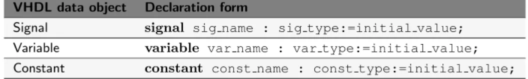
In VHDL there are several object types. Among the most frequently used we will mention the signalobject type, the variable object type and the
Listing 3.5: Example of a simple VHDL block.
1 FILE: my_sys.vhd
---2 -- library declaration
3 library ieee;
4 use ieee.std_logic_1164.all;
5
6 -- the ENTITY
7 entity circuit1 is
8 port (A,B,C : in std_logic;
9 F,G : out std_logic);
10 end circuit1;
11
12 -- the ARCHITECTURE
13 architecture circuit1_arc of circuit1 is
14 signal sig_1 : std_logic; -- signal definition 15 begin
16 process (a,b,c)
17 variable var_1 : integer; -- variable definition 18 begin
19 F <= not (A and B and C); -- signal assignment
20 sig_1 <= A; -- another signal assignment
21 var_1 := 34; -- variable assignment
22 end process; 23
24 G <= not (A and B); -- concurrent assignment
25 end circuit1_arc;
The constant is like a variable object type, the value of which cannot be changed. A signal object can be of different types; we saw before, for example, that a signal object can be of type std logic or of other types like integer, custom types, etc. The same applies for variable objects.
Before using any signal or variable, it is mandatory to declare them. Signals are declared at the top of the architecture body, just before the keyword begin. Variables must be declared inside theprocess construct and are local. An example is shown in line 14 and 17 of Listing 3.5.
As seen in line 19 and line 20 of Listing 3.5 when you want to assign a new value to an object of type signal you use the operator “<=”. Alternatively, when you want to assign a new value to an object of type variable you will use the operator “:=”, shown in line 21.
3.5 Summary 25
can happen instantly and it also means that you can take advantage of variables every time you need to implement a counter or to store values when inside a process.
In order to be able to introduce the use of a variable we had to employ theprocess construct, a construct that you are not yet familiar with. We will see more in details later on in the book that any time we need a non-concurrent execution environment where code lines are executed one after the other (like in C or Java), we will be using the process construct. Inside a process, all instructions are executed consecutively from top to bottom. However the process itself will be executed concurrently with the rest of the code (e.g. the instruction at line 24).
Always remember that the assignment of Listing 3.5 at line 24 and the execution of the process, are not executed consecutively but instead concurrently (all at the same time). Any hope that the execution of line 24 will happen before or after the execution of the process will only result in great disappointment.
As a final note, let us to remind that the type std logic only exists if you declare the libraryieee.std logic 1164.all as done in line 4 of Listing 3.5.
3.5 Summary
The entity declaration describes the inputs and outputs of your circuit. This set of signals is often referred to as the interface to your circuit since these signals are what the circuitry, external to the entity, uses to interact with your circuit.
Signals described in the entity declaration include amode specifier and atype. The mode specifier can be either anin or anout (or, as we will see later on, even an inout) while the type is either astd logic or
std logic vector.
The word bundle is preferred over the word bus when dealing with multiple signals that share a similar purpose. The word bus has other connotations that are not consistent with the bundle definition.
a bundle using a std logic vector type. Bundled signals such as these are always easier to work with in VHDL compared to scalar types such asstd logic.
The architecture describes what your circuit actually does and what its behavior is. Several possible implementations (models) of the same behavior are possible in VHDL. These are thedata-flow model, the
behavioral model, thestructuralmodel as well as any combination of them, generally calledhybridmodel.
3.6 Exercises
1. What is referred to by the word bundle?
2. What is a common method of representing bundles in black-box diagrams?
3. Why is it considered a good approach to always draw a black-box diagram when using VHDL to model digital circuits?
4. Write VHDL entity declarations that describe the following black-box diagrams:
a)
sys1 a in1
b in2 clk ctrl int
out b b)
sys2 input w
a data /8 b data /8
clk
dat 4 8 /
dat 5 3 /
5. Provide black-box diagrams that are defined by the following VHDL entity declarations:
a)
entity ckt_c is port (
bun_a, bun_b, bun_c : in std_logic_vector(7 downto 0);
lda, ldb, ldc : in std_logic;
reg_a, reg_b, reg_c : out std_logic_vector(7 downto 0));
3.6 Exercises 27
b)
entity ckt_e is port (
RAM_CS, RAM_WE, RAM_OE : in std_logic;
SEL_OP1, SEL_OP2 : in std_logic_vector(3 downto 0);
RAM_DATA_IN : in std_logic_vector(7 downto 0);
RAM_ADDR_IN : in std_logic_vector(9 downto 0);
RAM_DATA_OUT : out std_logic_vector(7 downto 0));
end ckt_e;
6. The following two entity declarations contain two of the most common syntax errors made in VHDL. What are they?
a)
entity ckt_a is port (
J,K : in std_logic;
CLK : in std_logic
Q : out std_logic;)
end ckt_a;
b)
entity ckt_b is port (
mr_fluffy : in std_logic_vector(15 downto 0);
mux_ctrl : in std_logic_vector(3 downto 0);
byte_out : out std_logic_vector(3 downto 0);
4
VHDL Programming Paradigm
The previous chapter introduced the idea of the basic design units of VHDL: the entity and the architecture. Most of the time was spent describing the entity simply because there is so much less involved compared to the architecture. Remember, the entity declaration is used to describe the interface of a circuit to the outside world. The architecture is used to describe how the circuit is intended to function.
Before we get into the details of architecture specification, we must step back for a moment and remember what it is we are trying to do with VHDL. We are, for one reason or another, describing a digital circuit. Realizing this is very important. The tendency for young VHDL programmers with computer programming backgrounds is to view VHDL as just another pro-gramming language they want or have to learn. Although many university students have used this approach to pass the basic digital classes, this is not a good idea.
in a concurrent manner1, meaning that all instructions are executed at once. Realizing this fact will help you to truly understand the VHDL programming paradigm and language.
4.1 Concurrent Statements
At the heart of most programming languages are the statements that form a majority of the associated source code. These statements represent finite quantities of actions to be taken. A statement in an algorithmic programming language such as C or Java represents an action to be taken by the processor. Once the processor finishes one action, it moves onto the next action specified somewhere in the associated source code. This makes sense and is comfortable to us as humans because just like the processor, we are generally only capable of doing one thing at a time. This description lays the foundation for an algorithmic method where the processor does a great job of following a set of rules which are essentially the direction provided by the source code. When the rules are meaningful, the processor can do amazing things.
VHDL programming is significantly different. Whereas a processor steps one by one through a set of statements, VHDL has the ability to execute a virtually unlimited number of statements at the same time and in a concurrent manner (in other words, in parallel). Once again, the key thing to remember here is that we are designing hardware. Parallelism, or things happening concurrently, in the context of hardware is a much more straightforward concept than it is in the world of software. If you have had any introduction to basic digital hardware, you are most likely already both familiar and comfortable with the concept of parallelism, albeit not within a programming language.
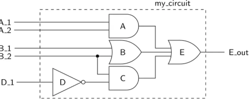
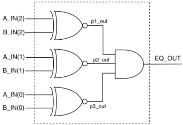
Figure 4.1 shows a simple example of a circuit that operates in parallel. As you know, the output of the gates are a function of the gate inputs. Any time that any gate input changes, there is a possibility that, after an opportune delay, the gate output will change. This is true of all the gates in Figure 4.1 or in any digital circuit in general. Once changes to the gate inputs occur, the circuit status is re-evaluated and the gate outputs may
1
4.1 Concurrent Statements 31
C D
B A
E E out
A 1 A 2 B 1 B 2
D 1
my circuit
Figure 4.1: Some common circuit that is well known toexecuteparallel
oper-ations.
change accordingly. Although the circuit in Figure 4.1 only shows a few gates, this idea of concurrent operation of all the elements in the circuit is the same in all digital circuits no matter how large or complex they are.
Since most of us are human, we are only capable of reading one line of text at a time and in a sequential manner. We have the same limitation when we try to write some text, not to mention enter some text into a computer. So how then are we going to use text to describe a circuit that is inherently parallel? We did not have this problem when discussing something inherently sequential such as standard algorithmic programming. When writing code using an algorithmic programming language, there is generally only one processing element to focus on at each given time. Everything more or less follows up in a sequential manner, which fits nicely with our basic limitation as humans.
The VHDL programming paradigm is built around the concept of ex-pression parallelism and concurrency with textual descriptions of circuits. The heart of VHDL programming is the concurrent statement. These are statements that look a lot like the statements in algorithmic languages but they are significantly different because the VHDL statements, by definition, express concurrency of execution.
Listing 4.1: VHDL code for the circuit of Figure 4.1.
-- library declaration
library IEEE;
use IEEE.std_logic_1164.all;
-- entity
entity my_circuit is
port ( A_1,A_2,B_1,B_2,D_1 : in std_logic;
E_out : out std_logic);
end my_circuit;
-- architecture
architecture my_circuit_arc of my_circuit is
signal A_out, B_out, C_out : std_logic;
begin
A_out <= A_1 and A_2;
B_out <= B_1 or B_2;
C_out <= (not D_1) and B_2;
E_out <= A_out or B_out or C_out;
end my_circuit_arc;
interpret these statements as actions that occur concurrently. Remember to keep in mind that the concept of concurrency is a key concept in VHDL. If you feel that the algorithmic style of thought is creeping into your soul, try to snap out of it quickly. The concurrent signal assignment is discussed in greater detail in the next section.
4.2 Signal Assignment Operator “<=” 33
Listing 4.2: Equivalent VHDL code for the circuit of Figure 4.1.
C_out <= (not D_1) and B_2;
A_out <= A_1 and A_2;
B_out <= B_1 or B_2;
E_out <= A_out or B_out or C_out;
Listing 4.3: Equivalent VHDL code for the circuit of Figure 4.1.
A_out <= A_1 and A_2;
E_out <= A_out or B_out or C_out;
B_out <= B_1 or B_2;
C_out <= (not D_1) and B_2;
Listing 4.4: Equivalent VHDL code for the circuit of Figure 4.1.
B_out <= B_1 or B_2;
A_out <= A_1 and A_2;
E_out <= A_out or B_out or C_out;
C_out <= (not D_1) and B_2;
4.2 Signal Assignment Operator “<=”
Algorithmic programming languages always have some type of assignment operator. In C or Java, this is the well-known “=” sign. In these languages, the assignment operator signifies a transfer of data from the right-hand side of the operator to the left-hand side. VHDL uses two consecutive characters to represent the assignment operator: “<=”. This combination was chosen because it is different from the assignment operators in most other common algorithmic programming languages. The operator is officially known as a signal assignment operator to highlight its true purpose. The signal assignment operator specifies a relationship between signals. In other words, the signal on the left-hand side of the signal assignment operator is dependent upon the signals on the right-hand side of the operator.
With these new insights into VHDL, you should be able to understand the code of Listing 4.1 and its relationship to its schematic shown in Figure 4.1. The statement “G <= A AND B;” indicates that the value of the signal named Grepresents an AND logic operation between the signals Aand B.
are of immediate interest to us are the process statement, the conditional signal assignment and the selected signal assignment.
In essence, the four types of statements represent the tools that you will use to implement digital circuits in VHDL. You will soon be discovering the versatility of these statements. Unfortunately, this versatility effectively adds a fair amount of steepness to the learning curve. As you know from your experience in other programming languages, there are always multiple ways to do the same things. Stated differently, several seemingly different pieces of code can actually produce the same result. The same is true for VHDL code: several considerably different pieces of VHDL code can actually generate the exact same hardware. Keep this in mind when you look at any of the examples given in this tutorial. Any VHDL code used to solve a problem is more than likely one of many possible solutions to that problem. Some of the VHDL models in this tutorial are presented to show that something can be done a certain way, but that does not necessarily mean they can only be done in that way.
4.3 Concurrent Signal Assignment Statements
The general form of a concurrent signal assignment statement is shown in Listing 4.5. In this case, the target is a signal that receives the values of the expression. An expression is defined by a constant, by a signal, or by a set of operators that operate on other signals. Examples of expressions used in VHDL code are shown in the examples that follow.
Listing 4.5: Syntax for the concurrent signal assignment statement.
<target> <= <expression>;
EXAMPLE 1.Write the VHDL code that implements a three-input NAND gate. The three input signals are named A, B and C and the output signal name is F.
4.3 Concurrent Signal Assignment Statements 35
to Example 1 is provided in Listing 4.6. Listing 4.6: Solution of Example 1.
1 -- library declaration
2 library IEEE;
3 use IEEE.std_logic_1164.all;
4 -- entity
5 entity my_nand3 is
6 port ( A,B,C : in std_logic;
7 F : out std_logic);
8 end my_nand3;
9 -- architecture
10 architecture exa_nand3 of my_nand3 is
11 begin
12 F <= NOT(A AND B AND C);
13 end exa_nand3;
my nand3 A
B C
F
This example contains a few new ideas that are worth further clarifica-tion.
There are header files and library files that must be included in your VHDL code in order for your code to correctly compile. These few lines of code are listed at the top of the code in Listing 4.6. The listed lines are more than what is needed for this example but they will be required in later examples. To save space, these lines will be omitted in some of the coming examples.
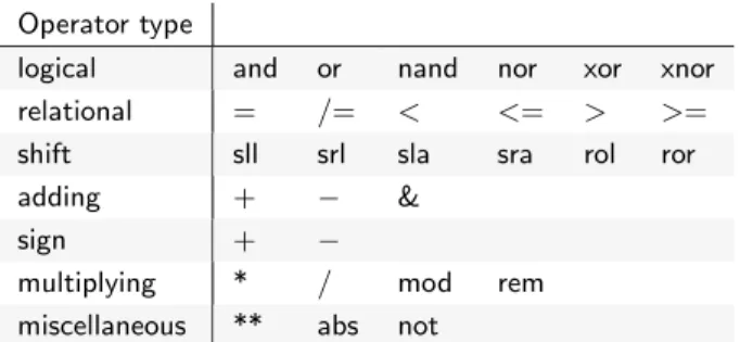
This example highlights the use of several logic operators. The logic operators available in VHDL are AND, OR, NAND, NOR, XOR and XNOR. The NOT operator is technically not a logic operator but is also available. Moreover, these logic operators are considered to be binary operators in that they operate on the two values appearing on the left and right-hand side of the operator. The NOT operator is a unary operator and for that, it only operates on the value appearing to the right of the operator.
In this solution, the entity only has one associated architecture. This is fairly common practice in most VHDL design.
In other words, the output F is re-evaluated any time a signal on the input expression changes. This is a key concept in truly understanding the VHDL, so you may want to read that sentence a few more times. The idea of concurrency is more clearly demonstrated in Example 2.
EXAMPLE 2. Write the VHDL code to implement the function expressed by the following logic equation:F3 =L·M ·N+L·M
SOLUTION.The black box diagram and associated VHDL code is shown in Listing 4.7.
Listing 4.7: Solution of Example 2.
-- library declaration
library IEEE;
use IEEE.std_logic_1164.all;
-- entity
entity my_ckt_f3 is
port ( L,M,N : in std_logic;
F3 : out std_logic);
end my_ckt_f3;
-- architecture
architecture f3_2 of my_ckt_f3 is
begin
F3<=((NOT L)AND(NOT M)AND N)OR(L AND M);
end f3_2;
my ckt f3 L
M N
F3
This example shows a one-line implementation of the given logic equation. An alternative solution to Example 2 is provided in Figure 4.8. This example represents an important concept in VHDL. The solution shown in Listing 4.8 uses some special statements in order to implement the circuit. These special statements are used to provide what is often referred to as intermediate results. This approach is equivalent to declaring extra variables in an algorithmic programming language to be used for storing intermediate results. The need for intermediate results is accompanied by the declaration of extra signal values, which are often referred to intermediate signals. Note in Listing 4.8 that the declaration of intermediate signals is similar to the port declarations appearing in the entity declaration, except that the mode specification (in,out orinout) is missing.
4.3 Concurrent Signal Assignment Statements 37
Listing 4.8: Alternative solution of Example 2.
-- library declaration
library IEEE;
use IEEE.std_logic_1164.all;
-- entity
entity my_ckt_f3 is
port ( L,M,N : in std_logic;
F3 : out std_logic);
end my_ckt_f3;
-- architecture
architecture f3_1 of my_ckt_f3 is
signal A1, A2 : std_logic; -- intermediate signals
begin
A1 <= ((NOT L) AND (NOT M) AND N); A2 <= L AND M;
F3 <= A1 OR A2;
end f3_1;
Despite the fact that the architecturesf3 2 andf3 1of Listing 4.7 and Listing 4.8 appear different, they are functionally equivalent. This is because all the statements are concurrent signal assignment statements. Even though thef3 1 architecture contains three CSAs, they are functionally equivalent to the CSA in f3 2 because each of the three statements is effectively executed concurrently.
tools at your disposal in order to model your circuits in the simplest way possible. Simple circuits have a higher probability of being understood and synthesized. But most importantly, a simple VHDL model is not related to the length of the actual VHDL code.
In Example 2, the conversion of the logic function to CSAs was relatively straightforward. The ease with which these functions can be implemented into VHDL code was almost trivial. Then again, the function in Example 2 was not overly complicated. As functions become more complicated (more inputs and outputs), an equation entry approach becomes tedious. Luckily, there are a few other types of concurrent construct that can ease its implementation.
4.4 Conditional Signal Assignment when
Concurrent signal assignment statements, seen before, associate one target with one expression. The term conditional signal assignment is used to describe statements that have only one target but can have more than one associated expression assigned to the target. Each of the expressions is associated with a certain condition. The individual conditions are evaluated sequentially in the conditional signal assignment statement until the first condition evaluates as true. In this case, the associated expression is evaluated and assigned to the target. Only one assignment is applied per assignment statement.
The syntax of the conditional signal assignment is shown in Listing 4.9. The target in this case is the name of a signal. The condition is based upon the state of some other signals in the given circuit. Note that there is only one signal assignment operator associated with the conditional signal assignment statement.
Listing 4.9: The syntax for the conditional signal assignment statement.
<target> <= <expression> when <condition> else
<expression> when <condition> else
<expression>;
4.4 Conditional Signal Assignmentwhen 39
EXAMPLE 3. Write the VHDL code to implement the function ex-pressed in Example 2. Use only conditional signal assignment statements in your VHDL code.
SOLUTION.The entity declaration does not change from Example 2 so the solution only needs a new architecture description. By reconsidering the same logic equation of Example 2,F3 =L·M·N+L·M, the solution to Example 3 is shown in Listing 4.10.
Listing 4.10: Solution of Example 3.
architecture f3_3 of my_ckt_f3 is
begin
F3 <= '1' when (L = '0' AND M = '0' AND N = '1') else '1' when (L = '1' AND M = '1') else
'0';
end f3_3;
There are a couple of interesting points to note about this solution.
It is not much of an improvement over the VHDL code written using concurrent signal assignment. In fact, it looks a bit less efficient in terms of the number of instructions.
If you look carefully at this code you will notice that there is in fact one target and a bunch of expressions and conditions. The associated expressions are the single digits surrounded by single quotes; the as-sociated conditions follow thewhenkeyword. In other words, there is only one signal assignment operator used for each conditional signal assignment statement.
The last expression in the signal assignment statement is the catch-all condition. If none of the conditions listed above the final expression evaluate as true, the last expression is assigned to the target.
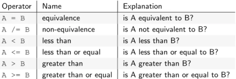
The solution uses relational operators. There are actually six different relational operators available in VHDL. Two of the more common relational operators are the “=” and “/=” relational operators which are the “is equal to” and the “is not equal to” operators, respectively. Operators are discussed at greater length in further sections.
(MUX). The next example is a typical conditional signal assignment imple-mentation of a MUX.
EXAMPLE 4. Write the VHDL code that implements a 4:1 MUX using a single conditional signal assignment statement. The inputs to the MUX are data inputs D3, D2, D1, D0 and a two-input control bus SEL. The single output is MX OUT.
SOLUTION. For this example we need to start from scratch. This of course includes the now famous black-box diagram and the associated entity statement. The VHDL portion of the solution is shown in Listing 4.11.
Listing 4.11: Solution of Example 4.
-- library declaration
library IEEE;
use IEEE.std_logic_1164.all;
-- entity
entity my_4t1_mux is
port(D3,D2,D1,D0 : in std_logic;
SEL : in std_logic_vector(1 downto 0);
MX_OUT : out std_logic);
end my_4t1_mux;
-- architecture
architecture mux4t1 of my_4t1_mux is
begin
MX_OUT <= D3 when (SEL = "11") else
D2 when (SEL = "10") else
D1 when (SEL = "01") else
D0 when (SEL = "00") else
'0';
end mux4t1;
my 4to1 mux D3
D2 D1 D0 SEL 2/
MX OUT
There are a couple of things to note in the solution provided in List-ing 4.11.
The solution looks somewhat efficient compared to the amount of logic that would have been required if CSA statements were used. The VHDL code looks good and is pleasing to the eye, qualities required for readability.
The “=” relational operator is used in conjunction with a bundle. In this case, the values on the bundle SEL are accessed using double quotes around the specified values. In other words, single quotes are used to describe values of individual signals while double quotes are used to describe values associated with multiple signals, or bundles.
4.4 Conditional Signal Assignmentwhen 41
Listing 4.12: Alternative solution to Example 4 accessing individual signals.
--- entity and architecture of 4:1 Multiplexer implemented using -- conditional signal assignment. The conditions access the -- individual signals of the SEL bundle in this model.
--- library declaration
library IEEE;
use IEEE.std_logic_1164.all;
-- entity
entity my_4t1_mux is
port (D3,D2,D1,D0 : in std_logic;
SEL : in std_logic_vector(1 downto 0);
MX_OUT : out std_logic);
end my_4t1_mux;
-- architecture
architecture mux4t1 of my_4t1_mux is
begin
MX_OUT <= D3 when (SEL(1) = '1' and SEL(0) ='1') else
D2 when (SEL(1) = '1' and SEL(0) ='0') else
D1 when (SEL(1) = '0' and SEL(0) ='1') else
D0 when (SEL(1) = '0' and SEL(0) ='0') else
'0';
end mux4t1;
for the SEL signal plus a catch-all else statement. We could have changed the line containing ’0’ to D0 and removed the line associated with the SEL condition of “00”. This would be functionally equivalent to the solution shown but would not be nearly as impressive looking. Generally speaking, you should clearly provide all the options in the code and not rely on a catch-all statement for intended signal assignment. Remember, a conditional signal assignment is a type of concurrent state-ment. In this case, the conditional signal assignment statement is executed any time a change occurs in the conditional signals (the signals listed in the expressions on the right-hand side of the signal assignment operator). This is similar to the concurrent signal assignment statement where the statement is executed any time there is a change in any of the signals listed on the right-hand side of the signal assignment operator.
theif-else constructs in algorithmic programming languages. We will touch more upon this relationship once we start talking about sequential statements.
The concept of working with bundles is very important in VHDL. Gener-ally speaking, if you can use a bundle as opposed to individual signals, you should. You will often need to access individual signals within a bundle. When this is the case, a special syntax is used (e.g. SEL(1)). Note that the code shown in Listing 4.12 is equivalent to but probably not as clear as the code shown in Listing 4.11. Be sure to note the similarities and differences.
4.5 Selected Signal Assignment with select
Selected signal assignment statements are the third type of signal assign-ment that we will examine. As with conditional signal assignassign-ment state-ments, selected signal assignment statements only have one assignment operator. Selected signal assignment statements differ from conditional assignment statements in that assignments are based upon the evaluation of one expression. The syntax for the selected signal assignment statement is shown in Listing 4.13.
Listing 4.13: Syntax for the selected signal assignment statement.
with <choose_expression> select
target <= <expression> when <choices>,
<expression> when <choices>;
EXAMPLE 5.Write VHDL code to implement the function expressed by the following logic equation:F3 =L·M·N+L·M. Use only selected signal assignment statements in your VHDL code.
SOLUTION.This is yet another version of themy ckt f3example that first appeared in Example 2. The solution is shown in Listing 4.14.
Listing 4.14: Solution of Example 5.
-- yet another solution to the previous example
architecture f3_4 of my_ckt_f3 is
begin
with ((L ='0' and M ='0' and N ='1') or (L ='1' and M ='1')) select
F3 <= '1' when '1',
'0' when '0',
'0' when others;
4.5 Selected Signal Assignmentwith select 43
Listing 4.15: Solution of Example 6.
-- library declaration
library IEEE;
use IEEE.std_logic_1164.all;
-- entity
entity my_4t1_mux is
port (D3,D2,D1,D0 : in std_logic;
SEL : in std_logic_vector(1 downto 0);
MX_OUT : out std_logic);
end my_4t1_mux;
-- architecture
architecture mux4t1_2 of my_4t1_mux is
begin
with SEL select
MX_OUT <= D3 when "11",
D2 when "10", D1 when "01", D0 when "00",
'0' when others;
end mux4t1_2;
One thing to notice about the solution shown in Listing 4.14 is the use of
thewhen othersclause as the final entry in the selected signal assignment
statement. In reality, the middle clause’0’ when ’0’could be removed from the solution without changing the meaning of the statement. In general, it is considered good VHDL programming practice to include all the expected cases in the selected signal assignment statement followed by
thewhen others clause.
EXAMPLE 6. Write the VHDL code that implements a 4:1 MUX using a single selected signal assignment statement. The inputs to the MUX are data inputs D3, D2, D1, D0 and a two-input control bus SEL. The single output is MX OUT.
SOLUTION.This is a repeat of Example 4 except that a selected signal assignment operator is used instead of a conditional signal assignment operator. The solution of Example 6 is shown in Listing 4.15. The black-box diagram for this example is the same as before and is not repeated here.
Once again, there are a few things of interest in the solution for Example 6 which are listed below.
only concurrent signal assignment statements.
Awhen othersclause is used again. In the case of Example 6, the
output is assigned the constant value of ’0’ when the other listed conditions of thechooser expression are not met.
The circuit used in this example was a 4:1 MUX. In this case, each of the conditions of thechooser expression is accounted for in the body of the selected signal assignment statement. However, this is not a requirement. The only requirement here is that the line containing the
when others keywords appears in the final line of the statement.
EXAMPLE 7.Write the VHDL code that implements the following circuit. The circuit contains an input bundle of four signals and an output bundle of three signals. The input bundle, D IN, represents a 4-bit binary number. The output bundle, SZ OUT, is used to indicate the magnitude of the 4-bit binary input number. The relationship between the input and output is shown in the table below. Use a selected signal assignment statement in the solution.
range of D IN SZ OUT
0000→ 0011 100
0100→ 1001 010
1010→ 1111 001
unknown value 000
SOLUTION.This is an example of a generic decoder-type circuit. The solution to Example 7 is shown in Listing 4.16.
my sz ckt