3100-3150 MCM
SLC / PLC PlatformModbus Master/Slave
Communications Module for PLC / SLC
April 7, 2014
Your Feedback Please
We always want you to feel that you made the right decision to use our products. If you have suggestions, comments, compliments or complaints about our products, documentation, or support, please write or call us.
How to Contact Us
ProSoft Technology5201 Truxtun Ave., 3rd Floor Bakersfield, CA 93309 +1 (661) 716-5100 +1 (661) 716-5101 (Fax) www.prosoft-technology.com [email protected]
Copyright © 2014 ProSoft Technology, Inc., All rights reserved.
3100-3150 MCM User Manual April 7, 2014
ProSoft Technology ®, ProLinx ®, inRAx ®, ProTalk ®, and RadioLinx ® are Registered Trademarks of ProSoft Technology, Inc. All other brand or product names are or may be trademarks of, and are used to identify products and services of, their respective owners.
ProSoft Technology
®Product Documentation
In an effort to conserve paper, ProSoft Technology no longer includes printed manuals with our product shipments. User Manuals, Datasheets, Sample Ladder Files, and Configuration Files are provided on the enclosed CD-ROM, and are available at no charge from our web site: www.prosoft-technology.com
Printed documentation is available for purchase. Contact ProSoft Technology for pricing and availability. North America: +1.661.716.5100
Asia Pacific: +603.7724.2080
Europe, Middle East, Africa: +33 (0) 5.3436.87.20 Latin America: +1.281.298.9109
Important Installation Instructions
Power, Input, and Output (I/O) wiring must be in accordance with Class I, Division 2 wiring methods, Article 501-4 (b) of the National Electrical Code, NFPA 70 for installation in the U.S., or as specified in Section 18-1J2 of the Canadian Electrical Code for installations in Canada, and in accordance with the authority having jurisdiction. The following warnings must be heeded:
A WARNING - EXPLOSION HAZARD - SUBSTITUTION OF COMPONENTS MAY IMPAIR SUITABILITY FOR CLASS I, DIV. 2;
B WARNING - EXPLOSION HAZARD - WHEN IN HAZARDOUS LOCATIONS, TURN OFF POWER BEFORE REPLACING OR WIRING MODULES
C WARNING - EXPLOSION HAZARD - DO NOT DISCONNECT EQUIPMENT UNLESS POWER HAS BEEN SWITCHED OFF OR THE AREA IS KNOWN TO BE NON-HAZARDOUS.
D THIS DEVICE SHALL BE POWERED BY CLASS 2 OUTPUTS ONLY.
MVI (Multi Vendor Interface) Modules
WARNING - EXPLOSION HAZARD - DO NOT DISCONNECT EQUIPMENT UNLESS POWER HAS BEEN SWITCHED OFF OR THE AREA IS KNOWN TO BE NON-HAZARDOUS.
AVERTISSEMENT - RISQUE D'EXPLOSION - AVANT DE DÉCONNECTER L'ÉQUIPEMENT, COUPER LE COURANT OU S'ASSURER QUE L'EMPLACEMENT EST DÉSIGNÉ NON DANGEREUX.
Warnings
North America Warnings
A Warning - Explosion Hazard - Substitution of components may impair suitability for Class I, Division 2.
B Warning - Explosion Hazard - When in Hazardous Locations, turn off power before replacing or rewiring modules.
Warning - Explosion Hazard - Do not disconnect equipment unless power has been switched off or the area is known to be nonhazardous.
C Suitable for use in Class I, division 2 Groups A, B, C and D Hazardous Locations or Non-Hazardous Locations. ATEX Warnings and Conditions of Safe Usage:
Power, Input, and Output (I/O) wiring must be in accordance with the authority having jurisdiction
A Warning - Explosion Hazard - When in hazardous locations, turn off power before replacing or wiring modules.
B Warning - Explosion Hazard - Do not disconnect equipment unless power has been switched off or the area is known to be non-hazardous.
C These products are intended to be mounted in an IP54 enclosure. The devices shall provide external means to prevent the rated voltage being exceeded by transient disturbances of more than 40%. This device must be used only with ATEX certified backplanes.
D DO NOT OPEN WHEN ENERGIZED.
Warning: This module is not hot-swappable! Always remove power from the rack before inserting or removing this module, or damage may result to the module, the processor, or other connected devices.
Battery Life Advisory
The batteries for the 3100/3150 are non-rechargable, replaceable, 3.6 volt lithium-thionyl-chloride, size 1/2AA, standardized part number (ER) 14250. This battery is easily user-replaceable and has a rated shelf life of 10 years @ 68 degrees F.
Markings
Electrical Ratings
Backplane Current Load: 800 mA @ 5 Vdc
Operating Temperature: 0°C to 60°C (32°F to 140°F)
Storage Temperature: -40°C to 85°C (-40°F to 185°F)
Shock: 30g Operational; 50g non-operational; Vibration: 5 g from 10 Hz to 150 Hz
Relative Humidity 5% to 95% (without condensation)
All phase conductor sizes must be at least 1.3 mm(squared) and all earth ground conductors must be at least 4mm(squared).
Label Markings
Agency Approvals and CertificationsANSI / ISA
ISA 12.12.01 Class I Division 2, GPs A, B, C, D CSA CB Certified IEC61010
ATEX EN60079-0 Category 3, Zone 2
EN60079-15
243333
ProSoft Technology, Inc. Page 5 of 130 April 7, 2014
Contents
Your Feedback Please ... 2
How to Contact Us ... 2
ProSoft Technology® Product Documentation ... 2
Important Installation Instructions ... 3
MVI (Multi Vendor Interface) Modules ... 3
Warnings ... 3
Battery Life Advisory ... 3
Markings ... 4
1 Quick Start Guide to the 3150-MCM 9 1.1 Implementation Guide ... 10
1.2 "ProSoft Tested" Test Documents ... 11
1.3 Quick Start Guide ... 12
1.4 The 3150-MCM At A Glance ... 13
2 Ladder Logic Overview 15 2.1 Operational Overview ... 16
2.2 Ladder Logic ... 17
2.2.1 Read Rung ... 17
2.2.2 Write Rung ... 17
3 Writing to the Module 19 3.1 Block Transferring to the Module ... 20
3.2 Communications Configuration [ BTW Block ID 255 ] ... 21
3.2.1 Power Up ... 21
3.2.2 Changing parameters during operation ... 21
3.2.3 Port 1 and 2 Configuration ... 23
3.2.4 System Configuration ... 26
3.3 Writing Into Module Data Memory [ BTW Block ID Codes 0 to 79 ] ... 30
3.3.1 Ladder Logic to Write Data to Module ... 30
3.3.2 Block Transfer Data Structure ... 31
3.4 Command List Configuration - Master Mode [ BTW Block ID Codes 80 to 99 ] ... 32
3.4.1 Command List Ladder Logic ... 32
3.4.2 Command List Structure... 33
3.4.3 Editing the Command List ... 36
3.5 Command Control Mode - Master Mode ... 37
3.5.1 The BTW Block Structure ... 37
3.5.2 Controlling the Commands ... 37
3.5.3 Example Command List ... 38
3.6 Event Initiated Commands - Master Mode [BTW Block ID Codes 100 to 119]... 39
3.6.1 Ladder Logic ... 39
Page 6 of 130 ProSoft Technology, Inc. April 7, 2014
4 Reading from the Module 43
4.1 Transferring data from the module [ BTR Block ID 0 to 79 ] ... 44
4.1.1 The Read Data Block Structure ... 44
4.1.2 Moving the data from the module to the processor ... 46
4.1.3 Ladder Logic to Read Module Data ... 47
4.1.4 Slave Error Code Table ... 47
4.1.5 Master Error Code Table ... 49
4.1.6 Error Status Codes ... 51
4.2 Pass-Through Mode: Slave Mode [ BTR Block ID 256 to 259 ] ... 53
4.2.1 The Block Structure ... 53
4.2.2 Receiving Register Writes [ BTR Block ID 256 and 257] ... 53
4.2.3 Receiving Single Bit Writes [ BTR Block ID 258 ] ... 54
4.2.4 Receiving Multiple Bit Writes [ BTR Block ID 259 ] ... 54
4.3 Decoding Command Done and Command Error Bits - Master Mode ... 55
4.3.1 The Block Structure ... 55
4.3.2 Ladder Logic ... 56
5 MODBUS Command Configuration 57 5.1 MCM Commands ... 58
6 Diagnostics and Troubleshooting 61 6.1 3100 PLC Platform LED Indicators ... 62
6.2 3150 SLC Platform LED Indicators ... 64
6.3 Troubleshooting: General ... 66
7 Reference 69 7.1 Product Specifications ... 70
7.1.1 General Specifications ... 70
7.2 New Features in Revision 2 ... 73
7.2.1 Modbus Master Driver ... 73
7.2.2 Modbus Slave Driver ... 74
7.3 Functional Overview ... 75 7.3.1 General ... 75 7.3.2 Hardware Overview ... 77 7.3.3 General Concepts ... 78 7.3.4 Data Flow ... 87 7.3.5 Modbus Addressing ... 90
7.4 Modbus Protocol Specification ... 93
7.4.1 Read Coil Status (Function Code 01) ... 93
7.4.2 Read Input Status (Function Code 02) ... 94
7.4.3 Read Holding Registers (Function Code 03) ... 95
7.4.4 Read Input Registers (Function Code 04) ... 96
7.4.5 Force Single Coil (Function Code 05) ... 96
7.4.6 Preset Single Register (Function Code 06) ... 98
7.4.7 Force Multiple Coils (Function Code 15) ... 98
7.4.8 Preset Multiple Registers (Function Code 16) ... 99
7.5 Jumper Configurations ... 100
7.6 Cable Connections ... 102
ProSoft Technology, Inc. Page 7 of 130 April 7, 2014 7.7.1 Overview... 104 7.7.2 Configuration Parameters ... 104 7.7.3 Module Operation ... 104 7.7.4 BTW Block ID ... 105 7.7.5 BTR Block ID ... 105
7.8 Example Ladder Logic ... 106
7.8.1 Slave Mode Examples ... 106
7.8.2 Master Mode Examples ... 106
7.9 Basic FAQs ... 107
7.9.1 3150-MCM as Master ... 107
7.9.2 3150-MCM as Slave ... 108
7.9.3 Port Configuration ... 108
7.10 Intermediate FAQs ... 110
7.10.1 Slave Port Offsets ... 110
7.10.2 Read / Write Block Configuration ... 111
7.10.3 Command Configuration ... 114
7.10.4 Slave Port Status ... 116
7.10.5 Master Port Status ... 117
8 Support, Service & Warranty 119 Contacting Technical Support ... 119
8.1 Return Material Authorization (RMA) Policies and Conditions... 121
8.1.1 Returning Any Product ... 121
8.1.2 Returning Units Under Warranty ... 122
8.1.3 Returning Units Out of Warranty ... 122
8.2 LIMITED WARRANTY ... 123
8.2.1 What Is Covered By This Warranty ... 123
8.2.2 What Is Not Covered By This Warranty ... 124
8.2.3 Disclaimer Regarding High Risk Activities ... 124
8.2.4 Intellectual Property Indemnity ... 125
8.2.5 Disclaimer of all Other Warranties ... 125
8.2.6 Limitation of Remedies ** ... 126
8.2.7 Time Limit for Bringing Suit ... 126
8.2.8 No Other Warranties ... 126
8.2.9 Allocation of Risks ... 126
8.2.10 Controlling Law and Severability ... 127
Index 129
Page 8 of 130 ProSoft Technology, Inc. April 7, 2014
ProSoft Technology, Inc. Page 9 of 130 April 7, 2014
1
Quick Start Guide to the 3150-MCM
In This Chapter
Implementation Guide ... 10
"ProSoft Tested" Test Documents ... 11
Quick Start Guide ... 12
The 3150-MCM At A Glance ... 13 Modbus Master/Slave Communication Module for the SLC platform
1 Open the sample ladder logic, MCM3EX1M.RSS in RSLogix500. The sample ladder is available on the inRAx product CD, or on the web site
www.prosoft-technology.com
2 Double-click "Controller Properties" and choose the appropriate SLC processor. Click OK.
3 Do not clear I/O. Click OK. 4 Double-click "I/O Configuration".
5 Choose the appropriate rack size. The sample ladder is configured with a 1747-A4 four-slot rack.
6 The 3150-MCM module is defined as a "1746-BAS-5/02, BASIC module, M0/M1 capable."
7 Drag this module to the appropriate slot in the rack. The sample ladder is configured with the 3150-MCM module in slot 1.
8 Select all of the following options and click OK:
o Move existing I:1/O:1 data and force data to I:x/O:x o Replace all ladder occurrences of I:1/O:1 with I:x/O:x
o Replace all ladder occurrences of M0:1/M1:1 with M0:x/M1:x where x is the new slot for the 3150-MCM module.
Configuration complete.
The 3150-MCM is now configured with the following parameters:
Data Flow as per the At-A-Glance diagram.
Port 1: Modbus RTU Master, 1 stop bit, no parity, 9600bps baud rate
Parameter Description
Command 1: Slave Node #1, Function code 3, 10 registers starting from 4x0201, store in database address 0 to 9, paged to N7:0 to N7:9
Command 2: Slave Node #1, Function code 4, 10 registers starting from 3x0211, store in database address 10 to 19, paged to N7:10 to N7:19 Command 3: Slave Node #1, Function code 1, 16 coils starting from 0x3521, store
in database address 20, paged to N7:20
Command 4: Slave Node #1, Function code 2, 16 inputs starting from 0x3201, store in database address 30, paged to N7:30
Commands 5 to 8: Disabled.
Port 2: Modbus RTU Slave, node address #1. No offsets.
Page 10 of 130 ProSoft Technology, Inc. April 7, 2014
1.1
Implementation Guide
Integration of the MCM module into a PLC or SLC application is easier if a series of steps are followed. In order to assist the first time users of our products in getting operational quickly, we have come up with this step-by-step
implementation guide.
First Time Users: Although the following steps are to assist you in implementing the module, we recommend that you attempt to experiment with the example logic provided on disk with the module or available off our www.prosoft-technology.com web site before laying out your application. This step will allow you to gain insight into how the module works prior to making decisions which will impact the long term success of the installation.
Start with one of the ladder logic programs provided on disk with the MCM, and then complete the following steps:
If you are entering the ladder logic by hand for the SLC, remember the following:
Configure the slot as a 1746-BAS module in 5/02 mode
Enter the Transfer Enable and Done bits as shown in the example logic 1 Edit the ladder logic (page 15) provided on disk as needed for the application
o Verify rack and slot location in program
o Modify ladder instruction addresses as needed
2 Setup the Communication Configuration (page 21) parameters
o Determine each port’s communication configuration requirements: Master or Slave, Parity, Stop Bits, Baud Rate, RTS delay requirements
o Identify memory mapping requirements
o Set the Read Data, Write Data , and the Command Block Count parameters
o Set the Slave and Master Error Table pointers are needed for the application
3 Setup the Command List if configuring a Master
o Review register map of slave device to build most effective memory map 4 Identify the module jumper requirements (page 100)
5 Make up the communication cables. Make sure that no matter what type of connection is being made up that a jumper is in place to satisfy the CTS signal. Normally this signal will be jumpered to RTS.
6 Place processor into the run mode
ProSoft Technology, Inc. Page 11 of 130 April 7, 2014
1.2
"ProSoft Tested" Test Documents
Through the efforts of our "ProSoft Tested" Program, we maintain a growing list of devices which we know have been interfaced to our module. In addition, we also have documented several of the devices which we have tested.
You can find more information on "ProSoft Tested" devices at www.prosoft-tested.com
Page 12 of 130 ProSoft Technology, Inc. April 7, 2014
1.3
Quick Start Guide
Installation of the 3100/3150-MCM module is easily accomplished. Installation into a system requires only a few steps. Following is a step-by-step procedure for getting an application operational:
Step Example User Application
Identify Rack position Rack 0 Group 2 Slot 0
Rack: ____ Group: _____ Slot: ______ Identify PLC Data Files usage BT Buffers: N7
BT Control: N7 Config File: N7 Data File: N10 BT Buffers: N____ BT Control: N____ Config File: N____ Data File: N_____
Ladder Logic Example on disk and in
Reference (page 69) section (Several examples to choose from)
Select the example closest to your application and modify as needed
Modify Logic for rack position PLC
BTR: Rung 2:0 BTW: Rung 2:1 SLC I:x.0 addresses O:x.0 addresses M0:x addresses M1:x addresses
Modify these instructions as needed based on the required rack position. You must configure the slot in the SLC.
Modify Logic for Data file usage N7 and N10 is used as data space for the module
Create files and change references from N7 and N10 Install card in rack Power down rack and install
module
Power down and install module Connect a comm cable to the
front of the module
Decide on cable type needed for application
Apply power to system and place PLC in RUN
Monitor the status files and the LEDs on the front of the module
When the hardware has been installed and the necessary programming has been downloaded to the processor, the system is ready (Presuming all other system components are safely ready).
ProSoft Technology, Inc. Page 13 of 130 April 7, 2014
Page 14 of 130 ProSoft Technology, Inc. April 7, 2014
ProSoft Technology, Inc. Page 15 of 130 April 7, 2014
2
Ladder Logic Overview
In This Chapter
Operational Overview ... 16
Ladder Logic ... 17
Data transfers between the processor and the ProSoft Technology module occur using the Block Transfer commands, in the case of the PLC, and M0/M1 data transfer commands, in the case of the SLC. These commands transfer up to 64 physical registers per transfer. The logical data length changes depending on the data transfer function.
The following discussions and Sections describes the data structures used to transfer the different types of data between the ProSoft Technology module and the processor. The term "Block Transfer" is used generically in the following discussion to depict the transfer of data blocks between the processor and the ProSoft Technology module. Although a true Block Transfer function does not exist in the SLC, we have implemented a pseudo-block transfer command in order to assure data integrity at the block level. Examples of the PLC and SLC ladder logic are included in the Reference (page 69) section.
Important: In order for the ProSoft Technology module to function, the PLC/SLC must be in the RUN mode, or in the REM RUN mode. If in any other mode (Fault/PGM), the module will stop all communications until block transfers resume.
Page 16 of 130 ProSoft Technology, Inc. April 7, 2014
2.1
Operational Overview
On power up the module moves a 255 into Word 1 of the BTR data file. This is a signal that the module needs to receive configuration data before proceeding any further. When the configuration is received the module will begin transferring data to and from the processor depending upon how many Read and Write block counts have been configured. When these are completed, the module will then transfer the command blocks if any have been configured.
ProSoft Technology, Inc. Page 17 of 130 April 7, 2014
2.2
Ladder Logic
The flow of the ladder logic is somewhat predefined by the way the module has been programmed. The expected flow of the ladder logic should be as follows:
2.2.1 Read Rung
1 Read Data from the Module. In the case of the PLC the module data will be transferred into the BTR Buffer. In the case of the SLC the module data will be accessed directly out of the M1 file
2 Decode the BTR Block ID number. Depending on the value of the BTR Block ID, copy the module data into the correct location in the ladder logic data table
3 Move the BTW Block ID Number from Word 1 of the BTR Buffer into Word 0 of the BTW Buffer. In the case of the SLC the transfer will actually be from Word 1 of the M1 file to Word 0 of the M0 file. The BTW Block ID number should be manipulated if necessary to assure that data is not overwritten in the module (The LIM test branch does this in the example logic)
4 Test for Event Initiated Commands and module configuration
2.2.2 Write Rung
1 Decode the BTW Block ID number and depending on the value move either data values, Command List values or Configuration values to the BTW buffer (M0 file in the SLC / PLC)
2 If the configuration transfer is enabled, then clear the configuration enable bit 3 In an Event Initiated Command is enabled, then clear the enable bit
4 Execute the BTW transfer. In the PLC this will be done by enabling the BTW instruction. In the SLC / PLC, this will be done by setting the Transfer Done bit (an Output bit has been assigned to this function in the design of the module)
Page 18 of 130 ProSoft Technology, Inc. April 7, 2014
ProSoft Technology, Inc. Page 19 of 130 April 7, 2014
3
Writing to the Module
In This Chapter
Block Transferring to the Module ... 20
Communications Configuration [ BTW Block ID 255 ] ... 21
Writing Into Module Data Memory [ BTW Block ID Codes 0 to 79 ] ... 30
Command List Configuration - Master Mode [ BTW Block ID Codes 80 to 99 ] ... 32
Command Control Mode - Master Mode ... 37
Event Initiated Commands - Master Mode [BTW Block ID Codes 100 to 119] ... 39
This section provides reference level information on the transfer of data from the PLC/SLC processor to the MCM module. This type of transfer allows the ladder logic to send configuration , command list and data to the module.
Page 20 of 130 ProSoft Technology, Inc. April 7, 2014
3.1
Block Transferring to the Module
Data transfer to the module from the processor is executed through the Block Transfer Write function. The different types of data which are transferred require slightly different data block structures, but the basic data structure is:
Word Name Description
0 BTW Block ID A block page identifier code. This code is used by the ProSoft module to determine what to do with the data block. Valid codes are:
BTW Code Description
0 to 79 Module Data Memory
80 to 99 Command List
100 to 120 Event Driven Writes
255 Module Communication
Configuration
1 to 63 Data The data to be written to the module. The structure of the data depends on the Block ID code. The following topics provide information on the different structures.
Important: Although the full physical 64 words of the data buffer may not be used, the BTW and M0 lengths must be configured for 64 words, otherwise module operation will be unpredictable.
BTW Block ID 0 1 2 3 4 : : : 63 Word Write Regs 150 to 199 Write Regs 200 to 249 Write Regs 250 to 299 Commands 1 to 5 Commands 6 to 10 Configuration Data BTW Block ID 3 4 5 80 81 255 Data Registers 50 wrds / blk 80 blks total (ID 0 - 79) Command List 10 wrds / cmd 5 cmds / blk 20 blks total (ID 80 to 99) PLC Data Table BTW Command MCM Memory Configuration 40 words (ID 255)
Data transfer from PLC to MCM: Data values and Command List entries are "paged" into the MCM module. The data type and location being written into corresponds to the BTW Block ID number. The BTW Block ID number is controlled by the MCM module, as discussed later in this section.
ProSoft Technology, Inc. Page 21 of 130 April 7, 2014
3.2
Communications Configuration [ BTW Block ID 255 ]
The ProSoft Technology firmware communication parameters must be configured at least once when the card is first powered up, and any time thereafter when the parameters must be changed.
3.2.1 Power Up
On power up, the module enters into a logical loop waiting to receive
configuration data from the processor. While waiting, the module sets the second word of the BTR buffer (the BTW Block ID) to 255, telling the processor that the module must be configured before anything else will be done. The module will continuously perform block transfers until the communications configuration parameters block is received. Upon receipt, the module will begin execution of the command list if present, or begin looking for the command list from the processor.
3.2.2 Changing parameters during operation
Changing values in the configuration table can be done at any time. The module does not accept any of the changes until the "re-configuration" process is
initiated. This can be accomplished in several ways, including: 1 Cycle power to the rack
2 Press the RESET pushbutton on the module (3100 only)
3 Move 255 into BTW Block ID position (See example logic when B3/0 is set) During this process, the "CFG" LED will toggle, giving a visual indication that the module has received the configuration block.
Important: Transferring the Communication Configuration Parameters to the module will force a reset of the communication port, as well as dropping DTR for 200 ms pulses to reset any attached hardware.
Page 22 of 130 ProSoft Technology, Inc. April 7, 2014 The configuration data block structure which must be transferred from the
processor to the module is as follows:
BTW Buffer Data Addr Name Example Value
0 BTW Block ID 255
Port 1 Config
1 N[ ]:0 Port Configuration Word 0 - Master
1 - Slave
2 N[ ]:1 Port Slave Addr 1
3 N[ ]:2 Baud Rate 5 4 N[ ]:3 RTS to TxD Delay 0 5 N[ ]:4 RTS Off Delay 0 6 N[ ]:5 Response Timeout 0 7 N[ ]:6 Intercharacter Delay 0 8 N[ ]:7 Setup Parm #1 0 9 N[ ]:8 Setup Parm #2 0 10 N[ ]:9 Setup Parm #3 0 Port 2 Config
11 N[ ]:10 Port Configuration Word 0 - Master
1 - Slave
12 N[ ]:11 Port Slave Addr 1
13 N[ ]:12 Baud Rate 5 14 N[ ]:13 RTS to TxD Delay 0 15 N[ ]:14 RTS Off Delay 0 16 N[ ]:15 Response Timeout 0 17 N[ ]:16 Intercharacter Delay 0 18 N[ ]:17 Setup Parm #1 0 19 N[ ]:18 Setup Parm #2 0 20 N[ ]:19 Setup Parm #3 0 21 N[ ]:20 Read Block Cnt 3 22 N[ ]:21 Write Block Cnt 1 23 N[ ]:22 Cmd Block Cnt 2 24 N[ ]:23 Slave Err Ptr 100 25 N[ ]:24 Master Error Ptr 120 26 N[ ]:25 BT Delay Cntr 0
27 N[ ]:26 Floating Point Offset 0
28 N[ ]:27 Read Block ID Start 0
29 N[ ]:28 Write Block ID Start 0
30 N[ ]:29 Spare 0
31 to 36 N[ ] :30 to N[ ] :35 Route Mode Slaves 1 to 6 0
ProSoft Technology, Inc. Page 23 of 130 April 7, 2014
3.2.3 Port 1 and 2 Configuration
DataAddr
Name Description
N[ ]:0 N[ ]:10
Port Configuration Word This register contains several communication configuration parameters encoded into the word. These are as follows:
Protocol Mode: The port’s protocol mode is selected by these bits:
Bits 210
000 Modbus Master - RTU Mode 001 Modbus Slave - RTU Mode 010 Modbus Master - ASCII Mode 7 bit 011 Modbus Slave - ASCII Mode 7 bit 100 Modbus Master - ASCII Mode 8 bit 101 Modbus Slave - ASCII Mode 8 bit
Pass Through Mode: The Slave Port operating mode is selected by this bit:
Bit 3
0 Pass Through Disabled
1 Pass Through Enabled
Routing Mode: Enable the Slave to Master Routing mode:
Bit 4
0 Routing Mode Disabled
1 Routing Mode Enabled
Stop Bits: The number of stop bits to be used is defined as follows:
Bits 13 12
0 0 One stop bit 0 1 Two stop bits
1 x Invalid Port Configuration
Parity: The parity mode to be used by the module is defined by this word as follows:
Bits 15 14
0 0 No parity 0 1 Odd parity 1 0 Even parity
1 1 Invalid Port Configuration N[ ]:1
N[ ]:11
Slave Address When the port is configured to operate in the Slave mode, the value entered in this register is used as the Modbus Slave address. Valid values range from 1 to 247.
Page 24 of 130 ProSoft Technology, Inc. April 7, 2014 Data Addr Name Description N[ ]:2 N[ ]:12
Baud Rate The baud rate at which the port is to operate. The available configurations are as follows:
Value Baud Rate
0 300 Baud 1 600 Baud 2 1200 Baud 3 2400 Baud 4 4800 Baud 5 9600 Baud 6 19200 Baud 7 38400 Baud
The module’s two ports are limited to an upper baud rate of either 19200 or 38400 baud. The module cannot be configured with one port at 19200 and the other at 38400. If an attempt is made to configure the module in this fashion, a Port Configuration Error will be returned.
N[ ]:3 N[ ]:13
RTS to TXD Delay This value represents the time in 1 ms increments to be inserted between asserting RTS, and the actual transmission of data. The delay, if greater in duration than the hardware time delay associated with CTS, will override the CTS line until the time-out is complete.
This configurable parameter is useful when interwith modem based devices, anytime line noise must be allowed to subside before data is transmitted, or if data transmissions must be slowed down. Valid values range from 0 to 65535 (0xffff). N[ ]:4
N[ ]:14
RTS Off Delay The value in this word represents the number of 1 ms time delay increments inserted after the last character is transmitted and before RTS is dropped. The module automatically inserts a one character width Off Delay, assuring that RTS does not drop until after the last character has been completely sent. Unless working under unusual conditions, this value will normally be configured with a value of 0. Valid value range from 0 to 65535 (0xffff). N[ ]:5
N[ ]:15
Message Response Timeout This register represents the message response timeout period in 1 ms increments. This is the time which a port configured as a Master will wait before re-transmitting a command if no response is received from the addressed slave. The value is set depending on the expected slave response times.
The allowable range of values is 0 to 65535(0xffff). If a zero value is entered, the module will default to a one second timeout value (1000 ms).
ProSoft Technology, Inc. Page 25 of 130 April 7, 2014 Data Addr Name Description N[ ]:6 N[ ]:16
Inter-character Timeout This register is used in situations where the end of message character timeout delay must be extended beyond the normal 3.5 character widths. The value entered represents the number of 1 ms intervals of 'no transmission' which will be counted prior to accepting a message. This parameter will be useful in satellite or packet radio installation where a data transmission may be split between two packets. Increasing this value beyond the system’s packet handling time will eliminate timeout errors. Valid values range from 0 to 65535 (0xffff) N[ ]:7
N[ ]:17
Setup Parameter #1 Master Mode : Not Used Slave Mode : Input Memory Start Address
Modbus Slave Mode:
This value defines the offset address into the 4000 word data space that the MCM Slave port will use when responding to function code 2 and 4
commands. For example, to start the address space at word 150, enter a 150. A function 2 or 4 command with an address of zero (10001 or 30001) will then start reading at word 150.
Valid values range from 0 to 3999. N[ ]:8
N[ ]:18
Setup Parameter #2 Master Mode : Not Used Slave Mode : Output Memory Start Address
Modbus Slave Mode
This value defines the offset address into the 4000 word data space that the MCM Slave port will use when responding to the function code 1, 5 or 15 commands. For example, to locate the output image at word 100, enter a 100. A function code 1 command with an address of zero (1) will then start reading at word 100.
Valid values range from 0 to 3999. N[ ]:9
N[ ]:19
Setup Parameter #3 Master Mode : Not Used Slave Mode : Holding Register Start Address
Modbus Slave Mode
This value defines the offset address into the 4000 word data space that the MCM Slave port will use when responding to the function code 3, 6, or 16 commands. For example, to locate address 40001 at word 100 in the module, enter a 100. A function code 3 command with an address of zero (40001) will then start reading at word 100.
Page 26 of 130 ProSoft Technology, Inc. April 7, 2014
3.2.4 System Configuration
Data Addr Name DescriptionN[ ]:20 Read Data Block Count This value represents the number of 50 word data blocks which are to be transferred from the MCM Module to the processor. The blocks returned from the module start at block 0 and increment from there. The maximum block count is 80.
For example, a value of 5 will return BTR Block ID data blocks 0, 1, 2, 3, and 4, or module registers 0 to 249.
If a value greater than 80 is entered, a System Configuration Error is activated
N[ ]:21 Write Data Block Count This value represents the number of 50 word data blocks which are to be transferred from the processor to the MCM Module. The module will use this value to return a BTW Block ID Number to the processor. The ladder logic can use this value to determine which data to move to the MCM via the Block Transfer Write. The maximum block count is 80.
For example, if a value of 5 is entered, the MCM will return BTW Block ID numbers 0, 1, 2, 3, and 4 to the ladder logic (Communications Configuration (page 21)).
If a value greater than 80 is entered, a System Configuration Error is activated
N[ ]:22 Command Block Count This value represents the number of 50 word Command Blocks which are to be transferred from the processor to the MCM Module. This value will be 0 if the module will not be configured with a Master port. The maximum block count is 20.
If a value greater than 20 is entered, a System Configuration Error is activated
N[ ]:23 Slave Error Block Pointer This value represents the relative starting position in the module’s data table within which the Modbus Slave Error Data Block is placed. The Slave Error Table is a 20 word block containing Slave port status and several communication counters. The error data can be placed anywhere in the module’s data space (0 to 3999). The contents of the Error Table can then be obtained as part of the regular Register Data.
If a value greater than 3980 is entered, a System Configuration Error is activated
ProSoft Technology, Inc. Page 27 of 130 April 7, 2014 Data Addr Name Description 0 49 50 99 100 149 150 199 200 249 250 Block ID 0 Block ID 1 Block ID 2 Block ID 3 Block ID 4 MCM Module Memory Block ID 0 to 79 Address : 0 to 3999
Slave Error Table Pointer= 100 Slave Error Table
The data registers 100 to 119 will contain the Slave Error Table.
N[ ]:24 Master Error Block Pointer This value represents the relative starting position in the module’s data register table within which the Master Error Data Block is placed. The error block (120 words in length) can be placed anywhere in the module’s data space (0 to 3999). The contents of the Error Table can then be obtained as part of the regular Register Data.
If a value greater than 3880 is entered, a System Configuration Error is activated
Page 28 of 130 ProSoft Technology, Inc. April 7, 2014 Data Addr Name Description 0 49 50 99 100 149 150 199 200 249 250 Block ID 0 Block ID 1 Block ID 2 Block ID 3 Block ID 4
Master Error Table
Data registers 120 to 240 will contain the Master Error Table.
Master Error Table Pointer= 120 MCM Module Memory
Block ID 0 to 79 Address : 0 to 3999
N[ ]:25 Block Transfer Delay Counter This is an empirical value used by the module to balance the amount of time the module spends block transferring and the amount spent handling port communications. The value entered is used as a loop counter in the module, where each time through the loop the count is incremented. When the count equals the Block Transfer Delay Counter a Block Transfer sequence is initiated. The range on this value is 0 to 255.
Example: In Master Mode applications with the module in a remote rack, the frequency of command execution can be improved by entering a value of 75 to 150. The value must be determined empirically. N[ ]:26 Floating Point Offset This value is used by the module’s Slave port driver
to support the read and write addressing of Floating Point registers when addressing registers > 7000 (Commonly called the Enron version of the Modbus protocol). The offset value is used as follows by the module:
MCM Reg Address = Floating Point Offset + (Reg Addr - 7000) * 2
The Floating Point Offset is not used on Pass Through Mode addressing. In the Pass Through mode, the address passed to the ladder logic is calculated as follows:
ProSoft Technology, Inc. Page 29 of 130 April 7, 2014
Data Addr
Name Description
N[ ]:27 Read Block ID Start This value determines the starting BTR Block ID number which will be returned from the module. For example, if the ladder logic needs to receive Blocks 2 through 5 from the module, the parameter should be configured with a '2' and the Read Block Count should be set to '4'. Valid values range from 0 to 79. N[ ]:28 Write Block ID Start This value determines the starting BTW Block ID
number which the module will return to the ladder logic. For example, if the ladder logic needs to write into Blocks 4 through 5 in the module, this parameter should be set to '4' and the Write Block Count should be set to '2'. Valid values range from 0 to 79. N[ ]:30 to
N[ ]:35
Route Mode Slave Address #1 to #6
These six addresses are provided for when the MCM module is configured with the Routing Mode Enabled. In this mode, any command which comes in the Slave port which matches one of the Route Mode
Addresses will be re-transmitted out the Master port. The response from this slave will be routed back to the host via the slave port.
Page 30 of 130 ProSoft Technology, Inc. April 7, 2014
3.3
Writing Into Module Data Memory [ BTW Block ID Codes 0 to 79 ]
Writing into the MCM register data space is accomplished using a Block Transfer Write with BTW Block ID codes from 0 to 79 followed by 50 words of data.
Caution: Care must be exercised with memory layout to assure that MCM read and write commands do not overwrite data being moved in from the processor ladder logic. Modbus data
cannot be moved into a 50 word block that is also updated by the processor. The ladder logic examples in the Reference (page 69) section address this concern.
3.3.1 Ladder Logic to Write Data to Module
The ladder logic required to move data to the module is a simple series of EQU-COP branches, or it can be implemented using indirect addressing. The way that we have implemented the transfer to the module in all of our example ladder logic is through a two step process, where:
Step 1: During the BTR process, the module will "feed" the ladder logic a BTW Block ID Number in the second word of the BTR Data Buffer. Ladder logic is implemented to accept this value, condition it if needed, and then to move the value to the actual BTW Block ID location. The ladder logic to do this is shown below: MOV A: N7:411 B: N7:310 LIM ADD A: 0 B: N7:310 C: N7:21 A: N7:310 B: N7:20 C: N7:310
Setting up the BTW Block ID Number
Located at the bottom of the BTR rung (Rung 0), this logic moves the BTW Block ID Number being received from the module and offsets it by the Read Block Count (N7:20) in order to assure that PLC data does not overwrite the data being returned from the module to the PLC.
Step 2: During the processing of the BTW rung, the ladder logic will test for the value in the BTW Block ID register and based on the value, copy data from the data table into the BTW Block Transfer buffer. This process requires that every BTW Block ID which will be processes be accounted for with a branch of logic. An example of the ladder logic required follows:
EQU COP
SRC A : N7:310
SCR B: 3 SRC: #N10:150DEST: #N7:311 COUNT: 50
ProSoft Technology, Inc. Page 31 of 130 April 7, 2014
Test BTW Block ID and move data to BTW Buffer
This branch, located in the BTW rung (rung 1) is an example of the logic that must be implemented for each data block to be move to the module.
3.3.2 Block Transfer Data Structure
The structure of the block transfer buffer when writing data to the module is shown below:
Word Name Description
0 BTW Block ID The block identifier number allows the MCM Module to decode which "50 word page" in the module's 4000 word data space the data is to be written. The data space to be written into can be determined by multiplying the BTW Block ID by 50. The result is the first word of the "page". As an example:
BTW Block ID Data Space
0 0 to 49
1 50 to 99
10 500 to 549
20 1000 to 1049
By paging the different data blocks into the module the processor can control the module data memory contents.
1 to 50 Data The data to be written to the module.
Page 32 of 130 ProSoft Technology, Inc. April 7, 2014
3.4
Command List Configuration - Master Mode [ BTW Block ID Codes 80
to 99 ]
An MCM Modbus Master port establishes communications and performs various communications functions based on the data which the user has placed in the command list. The command list consists of up to 100 individually configured command data blocks (10 words reserved per command) which are shared between the two available ports (in the case when the module is configured with two Master ports).
3.4.1 Command List Ladder Logic
This list, entered into the processor Data Table, is transferred to the module's memory using BTW Block ID codes 80 to 99 with each code representing a 50 word block, or 5 commands.
An example of the ladder logic to move the commands to the module is as follows: BTW Rack: 0 Module: 0 Group: 0 Control: N7:300 Data: N7:310 Continuous: N Length: 64 EQU COP SRC A : N7:310 SCR B: 80 SRC: #N10:150 DEST: #N7:311 COUNT: 50 EQU COP SRC A : N7:310 SCR B: 81 SRC: #N10:150 DEST: #N7:311 COUNT: 50 Transfer Command List
These two branches, located in the BTW rung (Rung #1), move two Command List blocks into the module. These blocks each contain 5 commands, allowing the User to enter up to 10 commands in the module.
To add additional commands, add branches as needed for 82 to 99.
ProSoft Technology, Inc. Page 33 of 130 April 7, 2014
3.4.2 Command List Structure
The structure of the block containing the Command List is shown in the diagram below:
Name Description
Port/Mode Select The Port/Mode Select parameter allows the application to select which port the MCM Module will use to execute the command, and whether the command will be performed continuously or only when a change in data is detected (Conditional), or under direct ladder logic control (Control). Valid values are:
Port/Mode Description
0 Disable Command
1 Port 1 Continuous Command
2 Port 2 Continuous Command
5 Port 1 Conditional Command
6 Port 2 Conditional Command
9 Port 1 Control Command
10 Port 2 Control Command
Continuous vs. Conditional : Function Codes 5, 6, 15, and 16 When configuring write commands in the Command List, the MCM Master driver can support two types of data write
commands; Continuous and Conditional. The difference between the two are:
Continuous : Commands entered as in this fashion will be executed every time the module's Command List is scanned.
Conditional: Conditional commands are executed only when a change in the block of data to be written is detected. Every time the Command List is scanned, the module will compare the data to be written against the data last written. If a change is detected in any value, bit or word, the entire data block controlled by the command is written.
Control Command Mode
In the Control Command Mode, the command will only be executed when the Command Enable Bit (Command Control Mode) transitions from 0 to 1. The command is executed once per transition (that is, the module performs some one-shot logic to assure that the command only executes one). To clear the one-shot in the module, the Command Enable Bit must change state from 1 back to 0.
Slave Address The slave address represents the Modbus slave address of the slave station to which the command is directed. Addresses should be entered in the decimal form.
Page 34 of 130 ProSoft Technology, Inc. April 7, 2014
Name Description
Function Code The function code entered in the table tells the MCM Module what command to execute.
Function Code Description
1 Read Output Status
2 Read Input Status
3 Read Multiple Data Registers
4 Read Input Registers
5 Force Single Coil (Latch/Unlatch)
6 Preset (Write) Single Data Register
15 Multiple Coil Latch/Unlatch
16 Preset (Write) Multiple Data Register Source Address The value represents the register or bit address, for both read
and write commands, from which data will be obtained. The distinction between the two is as follows:
When issuing a read command, the Source Register Address is the register location in the slave where the command will begin getting data
When issuing a write command, the Source Register Address is register in the module where the command will begin obtaining the data to be written to the slave.
Count The number of words or bits the Modbus command is to read or
write. Modbus Command Configuration for a detailed discussion on the word and bit lengths to be specified for the different commands.
Destination Address The value represents the register or bit address, for both read and write commands, to which data will be written. The distinction between the two is as follows:
When issuing a read command, the Destination Address is the register location in the module where the command will begin placing the data from the slave
When issuing a write command, the Destination Address is register in the slave where the command will begin placing the data to be written to the slave.
ProSoft Technology, Inc. Page 35 of 130 April 7, 2014
Name Description
Type The Type field is relevant only during a Function Code 3
command (Multiple Register Read). The Type field tells the module to execute word swapping on the data being received by that particular command.
This is extremely useful and important when reading floating point data (two words per value) from some instruments ( Some instruments store the words of their floating point data in the opposite orientation to that of the processor. In these case, swapping the words allows a ladder logic COP command to copy the data straight from an Integer file to a Floating Point file). The available options at this time are:
Type Description
0 Default value. Performs no swapping. 1 Swap words in each word pair received
from the slave during this command 2 Swap words in each word pair received
then swap the bytes within the words
3 Swap bytes within each word (no word swapping) If using a function 6 or 16 and the destination register is greater than 47000, use a 1 in this field to disable the Enron Extension. Polling Time Preset The Polling Time Preset value allows each command to have a
configurable execution frequency. In the module, a timer is maintained for each command. Once per second the timer is decremented, until it reaches zero. When the timer reaches zero, the command is enabled for execution, and the timer is reset to the Polling Timer Preset value. The resolution of the polling timer is 1 second. Valid values are 0 to 65535 (0xffff).
Page 36 of 130 ProSoft Technology, Inc. April 7, 2014
3.4.3 Editing the Command List
Entering the Command List is a matter of entering the correct values into the PLC data table. Using the ladder logic programming software, enter the values necessary to set up one or more valid commands.
Tip: When first setting up the Command List we recommend that you start out with one command. This one command will allow the module to begin transmitting if all else is OK (that is, ladder logic, cable is connected, and so on). When the module is transmitting, then attempt to communicate with the slave, then enter any other commands needed.
An example of a command list is shown below. Note that the commands can be entered in rows and that When the column definitions are understood, reviewing the Command List is very easy.
Example Command List
An example of multiple message configuration data blocks is shown in the following table (Columns 8 to 9 not shown for clarity).
0 1 2 3 4 5 6 7
Port Num Slv Add Func Code Src Add Cnt Dest Addr Type Poll Time N7:50 1 3 1 0 10 100 0 0 N7:60 1 3 4 50 20 100 0 0 N7:70 2 2 16 200 10 137 0 6 N7:80 6 2 16 210 10 150 0 0
ProSoft Technology, Inc. Page 37 of 130 April 7, 2014
3.5
Command Control Mode - Master Mode
Under some special operating conditions, it may be necessary for the ladder logic to be able to closely coordinate and control the execution of commands in the Command List. To accommodate this requirement, the MCM module supports something called the Command Control Mode.
When configured in the Command Control Mode, the ladder logic is able to provide Command Enable control on a per Command List entry basis. In addition, when used in conjunction with the Command Done Bits (page 55), the ladder logic is able to effectively one-shot each command if desired.
3.5.1 The BTW Block Structure
The structure of the Enable bits as they are written to the module in the BTW Block Transfer buffer is as follows:
Word Name Description
0 BTW Block ID The Command Enable bits are moved to the module during every BTW transaction. Therefore, all valid BTW Block ID numbers can be used here
1 to 50 Data Module data and Command List, as outlined above
51 to 56 Cmd Enable Bits These registers contain Command Enable Bits for each command in the command list, up to the first 96 commands. The Enable Bits are bit mapped into the words depending on their relative position in the Command List. The mapping within the words is as follows:
Word Cmds 51 1 to 16 52 17 to 32 53 33 to 48 54 49 to 64 55 65 to 80 56 81 to 96
Example: Word 51 bit 0 is Command #1 Enable
3.5.2 Controlling the Commands
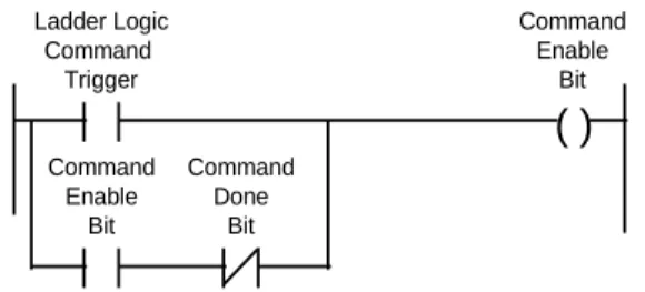
When a command is configured in the Command Control Mode, and when the module detects the Command Enable bit changing state from 0 to 1, the module will attempt to execute the command (Three attempts will be made to execute the command). If the command is successfully sent, the Command Done bit will be set. If an error occurs during the sending process, the Command Error bit will be set.
Page 38 of 130 ProSoft Technology, Inc. April 7, 2014 As example of the ladder logic which might be implemented to control a
command would appear in structure as follows:
( )
Ladder Logic Command Trigger Command Enable Bit Command Enable Bit Command Done BitThe simplest implementation would be to maintain a Binary table of Command Enable Bits which is copied to the BTW Buffer every transaction. The following branch of logic can be added to the BTW rung (transfer data to module):
COP
SRC: #B9:0 DEST: #N7:361 COUNT: 6
Copy the Command Enable Table of bits to the BTW Block Transfer Buffer
The Command Done and Error bits could then be copied into the same Binary File and referenced in ladder logic after being transferred. The following instruction can be added to the BTR rung (read data from module) accomplish this:
COP
SRC: #N7:462 DEST: #B9:6 COUNT: 12
Copy the Command Done and Error bits from the BTR buffer to the data table.
3.5.3 Example Command List
Commands can be controlled through configuration of the Command Enable
0 1 2 3 4 5 6 7
port Num Slv Add Func Code Src Add Cnt Dest Addr Type Poll Time N7:50 9 3 1 0 10 100 0 0 N7:60 10 3 4 50 20 100 0 0
Example Command List
An example where the command in N7:50 is configured as a Control Command Mode for Port 1 while the N7:60 command is configured for Port 2.
ProSoft Technology, Inc. Page 39 of 130 April 7, 2014
3.6
Event Initiated Commands - Master Mode [BTW Block ID Codes 100
to 119]
In addition to the continuously enabled commands which can be configured in the Command List, the MCM module also supports Event Initiated commands. These Event Commands can be used for reading/writing data conditionally with a slave. Example applications might include setting the time in a slave, resetting a batch counter, and so on.
Tip: One of the benefits offered by an Event Initiated Write Command (FC 5, 6, 15, 16) is that the data contents written to the slave are guaranteed to be coordinated with the execution of the command. Note that this is not necessarily the case when executing the commands out of the Command List.
3.6.1 Ladder Logic
Executing an Event Initiated Command is performed by transferring data to the BTW Buffer while the Block ID number is between 100 and 119, inclusive. The data block which is transferred, described in the next section, contains the data necessary for the module to encode a valid command The additions to the ladder logic which must be made to support this functionality are as follows:
MOV A: 100 B: N7:310 Event Cmd #1 B3/1
This branch is added to the Read rung, just above the MOV 255 to N7:310 branch. The B3/1 bit, selected here for example purposes only, is one-shot set in the ladder logic
EQU COP SRC A : N7:310 SCR B: 100 SRC: #N7:100DEST: #N7:311 COUNT: 10 (U) Event Cmd #1 B3/1
This branch is added to the BTW rung, and serves to copy the Event Initiated Command block structure to the module and then Unlatches the command enable bit which was set in the ladder program.
EQU COP SRC A : N7:310 SCR B: 100 SRC: #N7:100DEST: #M0:1.1 COUNT: 10 (U) Event Cmd #1 B3/1 PLC Version SLC Version
Page 40 of 130 ProSoft Technology, Inc. April 7, 2014
3.6.2 BTW Block Structure
The structure of the block containing the Event Initiated Command is shown in the following table.
BTW Word
Data Offset
Name Description
0 BTW Block ID The BTW Block ID is used by the module to determine that the Block Transfer buffer contains an Event Initiated Command. Valid values are between 100 and 119. The value determines the relative position in the Master Error Table.
1 N[ ]:0 Port Number The Port Number parameter allows the application to select which port the module will use to execute the command. Expected values are:
Port/Mode Description
1 Port 1
2 Port 2
2 N[ ]:1 Slave Address The slave address represents the Modbus slave address of the slave station to which the command is directed. Addresses should be entered in the decimal form. 3 N[ ]:2 Function Code The function code entered in the table tells the MCM
Module what command to execute.
Function Code Description
1 Read Output Status
2 Read Input Status
3 Read Multiple Data Registers
4 Read Input Registers
5 Force Single Coil (Latch/Unlatch)
6 Preset (Write) Single Data
Register
15 Multiple Coil Latch/Unlatch
16 Preset (Write) Multiple Data
Register
4 N[ ]:3 Source Address The value represents the register or bit address, for read commands, from which data will be obtained.
When issuing a read command, the Source Register Address is the register location in the slave where the command will begin getting data
When executing an Event Initiated Write command, this value has no meaning
5 N[ ]:4 Count The number of words or bits the Modbus command is to read or write.
ProSoft Technology, Inc. Page 41 of 130 April 7, 2014 BTW Word Data Offset Name Description 6 N[ ]:5 Destination Address
The value represents the register or bit address, for both read and write commands, to which data will be written. The distinction between the two is as follows:
When issuing a read command, the Destination Address is the register location in the module where the command will begin placing the data from the slave
When issuing a write command, the Destination Address is register in the slave where the command will begin placing the data to be written to the slave. 7 N[ ]:6 Type The Type field is relevant only during a Function Code 3 command (Multiple Register Read). The Type field tells the module to execute word swapping on the data being received by that particular command. Command List Structure has a complete discussion of this parameter 8 to 51 N[ ]:7 Write Data These register contain the write data values which will be
sent to the address slave per the Function Code selection. 0 1 2 3 4 5 6 7 8 9 Port Num Slv Add Func Code Src Add Cnt Dest Addr
Type Data Data Data
N7:100 1 3 1 0 10 100 0 0 0 0
N7:110 1 3 6 0 1 1 0 1267
Example Event Initiated Write Commands
The first command issues a FC 1 to Slave 3, reading 10 bits from bit 0 into register 100 in the module. The second commands writes the value 1267 to register 1 in the slave.
Page 42 of 130 ProSoft Technology, Inc. April 7, 2014
ProSoft Technology, Inc. Page 43 of 130 April 7, 2014
4
Reading from the Module
In This Chapter
Transferring data from the module [ BTR Block ID 0 to 79 ] ... 44
Pass-Through Mode: Slave Mode [ BTR Block ID 256 to 259 ] ... 53
Decoding Command Done and Command Error Bits - Master Mode .... 55
This section provides reference level details on the transfer of data from the PLC/SLC processor to the MCM module. This type of transfer allows the ladder logic to send configuration , command list and data to the module.
Page 44 of 130 ProSoft Technology, Inc. April 7, 2014
4.1
Transferring data from the module [ BTR Block ID 0 to 79 ]
When the Master port driver reads data from a slave or when a Host writes to the Slave port driver, the resulting data is placed into the ProSoft module’s data space (Addresses 0 to 3999). This Module Data space is the same block of memory that the PLC/SLC can write into per the above discussion.
The transfer of data from the ProSoft Technology module to the processor is executed through the Block Transfer Read function. The following topics detail the handling of the read data.
Important: Although the full physical 64 words of the data buffer may not be used, the BTR and M1 lengths must be configured for a length of 64 words, otherwise module operation will be unpredictable
4.1.1 The Read Data Block Structure
The BTR buffer definition is:
Word Name Description
0 BTR Block ID The ladder logic uses this value to determine the contents of the data portion of the BTR buffer. With some conditional testing in ladder logic, the data from the module can be placed into the PLC/SLC data table.
BTW Block ID 0 1 2 3 4 : : : 63 Word BTW Buffer BTW Block ID 0 1 2 3 4 : : : 63 Word BTR Block ID BTR Buffer
The relationship between the BTR Block ID number and the register table can be put into an equation:
Starting Register Address = Block ID Number * 50 Valid codes are between 0 and 79.
ProSoft Technology, Inc. Page 45 of 130 April 7, 2014
Word Name Description
1 BTW Block ID The module returns this value to the processor to be used to enable the movement of register data and command list blocks to the module. The BTW Block ID number is developed by the module based on the parameters entered in
parameters 21 and 22 of Block 255. This value is intended to only be a suggestion and to ease the ladder logic
programming requirements. If it is desired to develop a different data transfer series, this may be easily accomplished in ladder logic.
Valid codes are:
BTW Code Description
0 to 79 Module Data
80 to 99 Command List
100 to 119 Event Initiated Cmds
255 Module Configuration
2 to 51 Data The contents of the module’s Register Data space (0 to 3999). This data will contain data received from the slaves, data moved from the processor, and the Slave and Master Error Tables. The values will be 16 bit register values, and should be placed into integer files. Note that the user application ladder logic controls the placement and use of the data registers.
52 to 63 Command Done and Error Bits
Decoding Command Done and Command Error Bits - Master Mode
Page 46 of 130 ProSoft Technology, Inc. April 7, 2014
4.1.2 Moving the data from the module to the processor
Data which has been read from the slave devices (Master driver) or has been written from a host (Slave driver) is deposited into a 4000 word register table in the module. This table is addressed starting at 0 and going up to 3999.
The data register table is transferred from the module to the ladder logic through a paging mechanism designed to overcome the 64 physical word limit of the BTR instruction. The paging mechanism is outlined in the discussion above, but the important thing to understand is the relationship between the page numbers (BTR Block ID numbers) and the register addresses in the module.
The diagram also shows the layout for an example application. Note the number of blocks returned from the module to the ladder logic is determined by the value entered in the System Configuration "Read Block Cnt' register . In this example we have assumed a Read Block Count value of 5.
Read Data from Slaves to PLC These data registers (0 to 99) will be the destination addresses for the Commands in the Command List
N10:50 N10:100 N10:150 N10:200 PLC Data Addr Read Data Block PLC Data Memory 0 49 50 99 100 149 150 199 200 249 250 Block ID 0 Block ID 1 Block ID 2 Block ID 3 Block ID 4 MCM Module Memory Block ID 79 3999 Block ID 0 to 79 Address : 0 to 3999 N10:0
Slave Error Table Pointer= 100
Error Table
The data registers 100 to 119 will contain the Slave Error Table. Data registers 120 to 240 will contain the Master Error Table.
N10:250
Master Error Table Pointer= 120
Read Data Blocks from MCM Module
Note that this diagram assumes a Read Block Count value of 5, therefore returning Registers 0 to 249 from the module. This value can be altered as needed depending on the application.
ProSoft Technology, Inc. Page 47 of 130 April 7, 2014
4.1.3 Ladder Logic to Read Module Data
The ladder logic must be programmed to look at the BTR buffer, decode several words, and then take action. The following is an example of such ladder logic:
BTR BTR Enable BTW Enable PLC version Rack: 0 Module: 0 Group: 0 Control: N7:400 Data: N7:410 Continuous: N Length: 64 EQU COP SRC A : N7:310 SCR B: 0 SRC: #N7:412DEST: #N10:0 COUNT: 50 EQU COP SRC A : N7:310 SCR B: 1 SRC: #N7:412DEST: #N10:50 COUNT: 50
Example ladder to transfer data from module
This logic shows a method for moving data from the module to the PLC data table.
4.1.4 Slave Error Code Table
The MCM Module monitors the status of all Slave port commands. This status is communicated to the processor in the form of a Slave Error Code Table.
Important: The Slave Error Code Table is initialized to zero on power up, and every time the module receives the 255 configuration data block.
The Slave Error Table is a 20 word block. The location of the Error Table is determined by the Slave Error Table Pointer parameter in the Configuration Block. The structure of the data block is as follows:
Page 48 of 130 ProSoft Technology, Inc. April 7, 2014
Port 1 Status Codes
Word Example Addr
Name Description
0 N10:100 Current Port Status This value represents the current value of the error code for the port. This value will only be valid if the port is configured as a Slave. The possible values are described in the following section.
1 N10:101 Last Transmitted Error This value is the last error code transmitted to the master by this slave port. Error codes which can be expected in this field are 0, 1, 2, 3, and 6. The field will only be cleared by re configuring the module (Block ID 255).
2 N10:102 Total Msgs to this slave This value represents the total number of messages that have matched this slaves address on this port, whether the slave actually determined them to be good (worthy of response) or not.
3 N10:103 Total Responses from this slave
This value represents the number of good (non-error) responses that the slave has sent to the master on this port. The presumption is that if the slave is responding, the message was good. 4 N10:104 Total Msgs seen by this
slave
This value represents the total number of commands seen by the slave on this port, regardless of the slave address.
Port 2 Status Codes
Word Example Addr
Name Description
5 N10:105 Current Port Status Reference above for these descriptions 6 N10:106 Last Transmitted Error Reference above for these descriptions 7 N10:107 Total Msgs to this slave Reference above for these descriptions 8 N10:108 Total Responses from this
slave
Reference above for these descriptions 9 N10:109 Total Msgs seen by this
slave
Reference above for these descriptions