TECHNICAL UNIVERSITY OF CLUJ-NAPOCA
ACTA TECHNICA NAPOCENSIS
Series: Applied Mathematics, Mechanics, and Engineering Vol. 62, Issue I, March, 2019
FEA ANALYSIS OF THE INTERACTION CHAMBER FOR THE ELI-NP
ARRAY OF DETECTORS (ELIADE)
Sorin VLASE, Adina CRIȘAN, Călin ITU, Maria Luminița SCUTARU
Abstract: In the paper an analysis of the mechanical response of the interaction chamber for the ELI-NP array of detector is made. The vibration of the system is important considering that the very narrow γ beam must reach the target subjected to analysis. A good knowledge of the dynamical response of the lever and the target is necessary. The FEA analysis is made for the analysis of the interaction chamber, in order to obtain the dynamical response and the transmissibility of the system and can be used in practice in further research.
Key words: reaction chamber, FEA, vibration, eigenpulsation, ELI-NP
1. INTRODUCTION
The paper aims to analyze, from the point of view of mechanical response, the interaction chamber for the ELI-NP array of detector [19].
The interaction chamber (IC) for the ELIADE array is, together with the CCD camera to identify the γ beam, the main goal of the project developed by the team from the Transylvania University together the collegues from the IFA Măgurele. In the paper will be studied the vibration and the response of the mechanical structure to an external excitation. The results of the project can be extended to all the other experiments at ELI-NP that use small targets, but we will focus on making it work for the ELIADE array, to the details of which we have direct access. A dynamical analysis of the system is necessary [8], [14]-[17].
The IC-NRF specification is classified as structural and functional requirements specifications.
Structural requirement specification includes: IC-NRF must be implemented using at least stainless-steel 316 able to working under low-vacuum conditions (at least 10-3 mbar); must be integrated inside ELIADE structure; must hold inside the alignment system for the target; must host necessary vacuum instrumentation (volume
and weight of instrumentation will be defining in second phase of the project).
Functional requirement specification includes: to hosting a “target” used in NRF experiments with γ beam – The target is a material body (solid or liquid or gaseous) being hit by a γ beam; to providing inside IC-NRF a vacuum environment at 10-3 mbar; to providing integration within ELIADE structure which is holding a set of Ge detectors used during NRF experiments; to providing mechanical alignment with the γ beam (Gamma Beam Transportation System) in the experimental area; to providing alignment of the target holder with the γ beam prior starting the experiments; to providing (at request) the remote control of the mechanical alignment; to providing the remote control of the alignment of the target with γ beam on statistic bases; to providing easy insertion of the target in the target holder after alignment procedure of the target holder with γ beam.
alignment system; the detection system must assure a minimum 1: 100 “contrast” between array collided by γ beam and the rest of sensitive surface in order to assure a precise alignment of target with the γ beam; the alignment system components should be not influenced by the radiant γ flow and should not be accelerate aging in interaction with the γ beam.
The proposed solutions for alignment system use a γ beam detection system that provide information to a computer using a data acquisition or an image capture system. In front of digital camera, a γ beam to visible beam converter (scintillator lens) must be inserted. Using Ge based detectors or an optical system including scintillator, mirror and sCMOS camera, an image of the γ beam must be acquired by the alignment control system (in our case a computer that is linked to the γ beam detectors). If is used a digital camera this will be placed out of γ beam direction in order to avoid interaction between γ photons and camera sensitive pixels. The computer will be endowed with programs that will implement an algorithm able to quick scan and detect the most intense area collided by the γ beam. This algorithm will command the acquisition of signals from detectors, will compare the values or images with previous values or images and will sense the gradient in order to find out the sense commanded for pushers that will act on IC-NRF and will move this. The system will be considered aligned when the signal acquired by the detection system will reach a maximum value. The IC-NRF will be act be 6 or 8 linear actuators that will provide the alignment in two plans: orthogonal on γ beam direction and centered with the γ beam. The movement of the actuators will be inter-correlated by the computer.
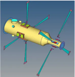
In Figure 1 is presented IC-NRF – first constructive solution integrated within ELIADE structure.
In order to assure the precision for the alignement system it is necessary to know the respons of the system to an external step load and the vibration of the lever where is situated the target (in this area must to act the γ beam) [1], [2], [5], [25], [28].
Fig. 1. The sketch of the interaction chamber
Fig. 2. Front view of the interaction chamber
Fig. 4. The lever with the target
2. FEA ANALYSIS
This constructive solution is defined as a solution based on the following assumptions: IC-NRF is integrated within the ELIADE structure using manual adjustable arms; the mechanical alignment will be done using the manual adjustable arms and the result will be a fixed symmetrization position of the IC-NRF. No other adjustment will be possible during experiments; the alignment of the target holder with the gamma beam will be made by using a xyz alignment system inside the IC_NRF. The position of the target holder will be fixed by using the integrated alignment system with the CCD camera. A remote control of this system allows the operator to make some adjustments of the position of the target during experiments on statistical bases.
Fig. 5. Half section of the interaction chamber
In Fig.5 is presented the model used in FEA analysis[27]. The element that presents interest for us is the lever with the target at the end. This element is very elastic and can have a great
transmissibility. This can decrease the precision of the command system.
Fig. 6. The FEA model of the lever with the target
FEA try to establish how big will be the displacement of the targen when the amplitude of the vibration of the end point (basis) is considered as unit [3],[18],[20],[24]-[26].
3. RESULTS
Using the model presented in Fig.5 a FEA for the interaction chamber is perform. The first mode of vibration is presented in Fig.6.
Fig. 6. 1st mode of vibration (15,15 Hz)
Fig. 8. 2nd mode of vibration (19,24 Hz)
Following the FEA analysis of the structure, one can observe the problem that the target holder is long and therefore has a high elasticity. As a result, the ground vibrations will be amplified here. For this, only the arm, considered as one of the heads, is studied. This excited ground is considered to be a vibration with an unitary amplitude. It is found that the vibration mode for which a maximum displacement of the target is obtained (ie transmissibility is maximal) is mode 8 and in this case the vibrations of the base increase 13 times.
Table 1. Eigenfrequencies [Hz] No. Frequency [Hz]
1 19,24
2 85,66
3 121,43
4 237.96
5 448,04
6 463,07
7 770,53
8 817,54
9 1001,46
10 1151,26
11 1372,14
12 1600,38
13 1705,74
14 2099,35
15 2371,73
In Fig. 7 it can be seen that maximum amplification is obtained for the eigenmode 8 and is about 13 times. It results, as a subject of
later request, that this arm should be redesigned so that the amplification achieved is much lower. This can be achieved by changing the row material and redesigning its shape so as to ensure a less transmissibility of the amplitude of vibration from the ground to the target [4],[6],[7],[9]-[13],[21].
4. CONCLUSION
A raw analysis of possible errors illustrates some important aspect that must be taken in consideration at the design of final solution. The necessity to assure a “pre-alignment” phase in order to settled the IC-NRF position close as possible from the γ beam. The positioning will be assured using a classical visible laser beam alignment system connected at the same alignment computer system. Through the building foundation must be made rigid fixation of all system elements related to the interaction chamber but also those related to γ beam source. The study of the vibration of the system and the transmissibility from the ground to the target is made. The change of the row material and a redesign of its shape so as to ensure a less transmissibility of the amplitude of vibration it is imposed. A problem for future research can be the dilatation of different components and the eventually differences of temperature. These should be compensated by the computer that assures the control of IC-NRF actuators (pushers). Thus, temperature sensors should be placed in whole room of ELI-NP system and temperature should be monitored too. Another factor that can influence the precision in positioning of IC-NRF is the shape of mechanical links between actuators and IC. A calibration procedure will assure the corrections of control procedures improving the precision in IC alignment. The principles of the alignment system can be studied studied before and independently getting the γ beam.
5. REFERENCES
dynamics simulation of cranes, Multibody Syst Dyn 25: 131–143,2011
[2] Gerstmayr, J., Schöberl, J., A 3D Finite Element Method for Flexible Multibody Systems, Multibody System Dynamics, Volume 15, Number 4, 305–320,2006. [3] Hartog, JP, Advanced Strenght of Materials,
Dover Pubications, 1987.
[4] Heitz, T., Teodorescu-Draghicescu,H., Lache, S., Chiru, A.,Vlase, S., Calin, M.R., Advanced T700/XB3585 UD carbon fibers-reinforced composites. Journal of Optoelectronics and Advanced Materials, Vol.16, Issue 5-6, pp.568-573, 2014.
[5] Ibrahimbegović, A., Mamouri, S., Taylor, R.L., Chen, A.J., Finite Element Method in Dynamics of Flexible Multibody Systems, Multibody System Dynamics , Volume 4, Numbers 2–3, 195–223,2000.
[6] Itu, C, Öchsner, A, Vlase, S, Marin IM,
Improved rigidity of composite circular
plates through radial ribs. Proceedings of the
Institution of Mechanical Engineers, Part L: Journal of Materials: Design and
Applications. doi.org/10.1177/
1464420718768049, online: April 16, 2018. [7] Katouzian, M, Vlase, S, Calin, MR,
Experimental procedures to determine the
viscoelastic parameters of laminated
composites. Journal of Optoelectonics and
Advanced Materials, Vol.13, Issue: 9-10, p.1185 -1188, 2011.
[8] Khulief, Y.A., On the finite element dynamic analysis of flexible mechanisms. Computer Methods in Applied Mechanics and Engineering, Volume 97, Issue 1, Pages 23– 32,1992.
[9] Marin, M., An approach of a heat-flux dependent theory for micropolar porous
media. Meccanica, vol. 51, No.5,
pp.1127-1133, 2016.
[10] Marin, M, Baleanu, D, Vlase, S, Effect of
microtemperatures for micropolar
thermoelastic bodies. Structural Engineering
and Mechanics, Vol. 61, Issue: 3, pp. 381-387, 2017.
[11] Marin, M., Vlase, S., Paun, M., Considerations on double porosity structure
for micropolar bodies. AIP Advanced, Vol. 5, Issue 3, art. Number 037113,2015
[12] Modrea, A, Vlase, S, Teodorescu-Draghicescu, H., Mihalcica, M , Calin, MR, Astalos, C, Properties of advanced new
materials used in automotive engineering.
Optoelectronics and Advanced Materials-Rapid Communications, Vol.7, Issue:5-6, p.452-455, 2013.
[13] Modrea, A, Vlase, S, Calin, MR, Peterlicean, A, The influence of dimensional and structural shifts of the elastic constant
values in cylinder fiber composites. Journal
of Optoelectonics and Advanced Materials, Vol.15, Issue:3-4, p.278-283, 2013.
[14] Negrean, I., New Formulations in
Analytical Dynamics of Systems, published in
Acta Technica Napocensis, Series: Applied Mathematics, Mechanics and Engineering, Vol. 60, Issue I, ISSN 1221-5872, pp. 49-56, 2017.
[15] Negrean, I., Advanced Equations in
Analytical Dynamics of Systems, published in
Acta Technica Napocensis, Series: Applied Mathematics, Mechanics and Engineering, Vol. 60, Issue IV, ISSN 1221-5872, pp. 503-514, 2017.
[16] Negrean I., Generalized Forces in
Analytical Dynamics of Systems, published in
Acta Technica Napocensis, Series: Applied Mathematics, Mechanics and Engineering, Vol. 60, Issue III, ISSN 1221-5872, pp. 357-368, 2017.
[17] Negrean I., Advanced Notions in Analytical
Dynamics of Systems, published in Acta
Technica Napocensis, Series: Applied Mathematics, Mechanics and Engineering, Vol. 60, Issue IV, ISSN 1221-5872, pp. 491-502, 2017.
[18] Scutaru, M.L., Vlase, S., Some Properties of Motion Equations Describing the Nonlinear Dynamical Response of a
Multibody System with Flexible Elements.
Journal of Applied Mathematics, Article Number: 628503, 2012.
[20] Teodorescu-Draghicescu, H , Stanciu, A, Vlase, S, Scutaru, L, Calin, MR, Serbina, L,
Finite element method analysis of some
fibre-reinforced composite laminates.
Optoelectronics and Advanced Materials-Rapid Communications, Volume: 5 Issue: 7 Pages: 782-785, 2011.
[21] Teodorescu-Draghicescu, H, Vlase, S , Scutaru, L , Serbina, L , Calin, MR,
Hysteresis effect in a three-phase polymer matrix composite subjected to static cyclic
loadings. Optoelectronics and Advanced
Materials-Rapid Communications, Volume: 5 Issue: 3-4 Pages: 273-277, 2011.
[24] Vlase,S., Finite Element Analysis of the Planar Mechanisms: Numerical Aspects. In Applied Mechanics - 4. Elsevier, pp.90-100,1992.
[25] Vlase, S. Danasel, C. Scutaru, M. L. et al., Finite Element Analysis of a Two-Dimensional Linear Elastic Systems with a
Plane "Rigid Motion". Romanian Journal of
Physics, Vol. 59 (5-6), pp. 476-487, 2014. [26] Vlase,S., Dynamical Response of a
Multibody System with Flexible Elements
with a General Three-Dimensional
Motion. Romanian Journal of Physics,
Vol. 57 (3-4),pp. 676-693, 2012.
[27] Vlase, S., Munteanu, M.V., Scutaru, M.L., On the Topological Description of the
Multibody Systems. 19th International
Symposium of the
Danube-Adria-Association – for – Automation – and - Manufacturing, Trnava, Slovakia, pp. 1493-1494, 2008.
[28] Vlase, S.; Teodorescu, P. P., Elasto-Dynamics of a Solid with a general "Rigid" Motion using FEM Model. Part I. Theoretical
Approach. Romanian Journal of
Physics, Vol.: 58(7-8),pp. 872-881, 2013.
Analiza FEA a camerei de interacție pentru sistemul de detectori ELIADE din cadrul proiectului ELI-NP
Rezumat. În lucrare se face o analiză a răspunsului dinamic al camerei de interacțiune proiectul ELI-NP. Vibrațiile sistemului sunt un element foarte important, având în vedere faptul că fascicolul γ foarte îngust trebuie să atingăținta supusă analizei. O cunoaștere bună a răspunsului dinamic al brațului de susținere și al țintei este necesară. Analiza FEA este făcută pentru studiul camerei de interacție, pentru a obține răspunsul dinamic și transmisibilitatea sistemului iar rezultatele obținute pot fi utilizate în practică pentru cercetări ulterioare.
Cuvinte cheie: camera de interacție, MEF, vibratii, pulsatii proprii, ELI-NP
VLASE Sorin, Prof. Dr.hab., Head of Department, Transylvania University of Brașov, Department of Mechanical Engineering, [email protected], Office phone: +40-268-418992, 30, Castelului, 500014, Brașov, home phone: +40-722-643020.
CRIȘAN Adina, Senior lecturer Ph.D., Department of Mechanical Systems Engineering, Technical University of Cluj-Napoca, [email protected], Office Phone 0264/401750.
ITU Călin, Assist. Prof., Ph.D., Transylvania University of Brașov, Department of Mechanical Engineering, [email protected], Office phone: +40-268-418992, 29, B-dul Eroilor, 500036, Brașov.
![Fig. 6. The FEA model of the lever with the target FEA try to establish how big will be the displacement of the targen when the amplitude of the vibration of the end point (basis) is considered as unit [3],[18],[20],[24]-[26]](https://thumb-us.123doks.com/thumbv2/123dok_us/7995365.2120169/3.918.511.789.588.1055/model-target-establish-displacement-targen-amplitude-vibration-considered.webp)

