TECHNICAL UNIVERSITY OF CLUJ-NAPOCA
ACTA TECHNICA NAPOCENSIS
Series: Applied Mathematics, Mechanics, and Engineering Vol. 58, Issue I, March, 2015
DEVELOPMENT OF A MULTI-ROOM BUILDING THERMAL MODEL
FOR USE IN THE DESIGN PROCESS OF ENERGY MANAGEMENT
SYSTEMS
Ciprian LAPUSAN, Radu BALAN, Ciprian RAD, Alin PLESA
Abstract: To satisfy ever increasing needs for efficiency and environment protection the control systems for house energy management integrates more and more complex control algorithms and intelligent sensor networks. In order to develop such systems suitable building dynamics models are needed both for the control strategies and for the product testing and optimization procedures in the design phase. In this paper the development of an analytical multi-room
building thermal model for use in the development process of house energy management systems is presented. The proposed model is tested by implementing in Matlab/Simulink the model of a building with 4 rooms.
Key words: multi-room building model, building thermal dynamics, building energy management.
1. INTRODUCTION
In the last years the research in smart management and optimization of energy consumption in building has experienced a vast development. Buildings are responsible of 40% from the total energy consumed at global scale [1], making the impact of this researches very important in improving/reducing the problems related to the climate changes and limited amount of natural resources. In EU 2020 Strategy one of the five target headlines states a 20% reduction of primary energy consumption until 2020 (compared with 1990) [2].
The implementation of the advanced control strategies in the Building Energy Management Systems (BEMS) promises to provide potential savings of approximately 30% of energy consumed in a building [3]. BEMS rely on advanced strategies that run on dedicated computers in order to manage, control and monitor building technical services (HVAC, lighting etc.) and the energy consumption of devices used by the building. From the total energy used by a building almost 80% is used for heating, so improving the heating process become very important when discussing about energy optimization in building [4].
In this context development of suitable dynamics models for the building became mandatory due to the use in the system design process and also for use in the control strategies [5]. In the literature the authors mainly focus on developing simplified building models with lumped parameters where the entire building is reduce to one concentrated element [6,7,8]. This approach is motivated by computation limits of the control hardware and for ease of calculation of energy balance in the building.
The development of modern control hardware in the last years and the big process time constant allows the implementation of more complex control strategies that can use detailed dynamic models for building.
2. ANALYTICAL MODEL
DEVELOPMENT
The dynamic model of the building is developed taking in consideration its application in BEMS design process. In order to allow the development of vast types of experiments, the model must accurate describe the physical phenomena that influence the thermal behavior of each room that compose the building and allow access to different process parameters.
2.1System definition
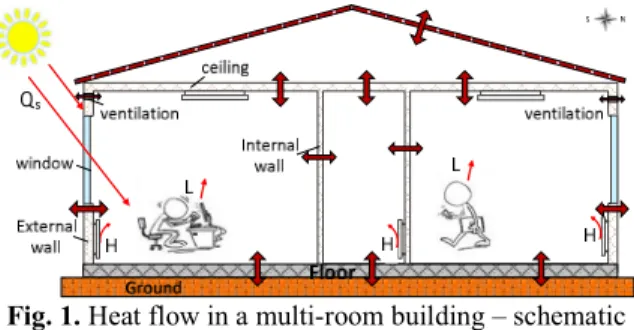
The modeled building is thought to be a set of rooms bounded by walls which are in thermal contact with the external environment and neighbor rooms through conductive, convective and radiation heat transfer. The external environment can be defined by various elements like climatologically conditions (temperature, wind velocity and solar radiation), effects due to precipitation and humidity transport, effects of near or adjacent buildings etc. In this work, for the outer conditions, the model takes in consideration the effect of air, the effect of ground temperature and solar radiation.
The building model includes also internal elements that are characterized by thermal resistance and capacities. The internal elements for one room include all the elements inside the room, except: the exterior and interior walls, roof, ground floor and windows. The air capacity inside the room is also modeled.
Fig. 1. Heat flow in a multi-room building – schematic representation
The temperature differences between different zones or elements inside the building will cause heat flows (Fig. 1), resulting in time-varying indoor climate. The flow is always
towards the areas with lower temperature; in this way the system always tries to equalize the temperature. The heat balance for a room can be mathematically expressed by:
( ) = ( ) + ( ) (1)
where:
( ) – represents the heat flows supplied by all heat sources that influence the thermal dynamics of the house.
( ) – represents the total convective, conductive and radiant heat loses of the building
( ) – is the heat flow caused by the energy stored in the building construction elements.
Mainly the building heat loses are caused by the heat flow through exterior walls and ventilation. Among the elements that produce heat inside the building one can mention: heating / cooling systems, sun light effect on the building, people inside the building and different electrical devices that generate heat.
2.2Heat flow through building walls and windows
The phenomena that cause the heat transfer are: conduction, convection and radiation. In development of the model for walls heat dynamics all three phenomena are considered.
In [10] Achterbosch & all presented a method for modeling the convection and radiation heat transfer near walls. The phenomena can be described by equations 2 and 3.
= ( − ) (2)
where – is the convective heat transfer coefficient;
= ( − ) (3)
where – is the radiation heat transfer coefficient;
The coefficients and can be calculated [10], and the total heat transfer caused by these two phenomena is computed using = +
For defining the conduction heat flow through construction elements the Fourier equations are used. For one dimensional heat flow the equation is:
= ∙ (4)
where C - is the heat capacity per unit area of the construction element
R- is the heat resistance of the construction element
The building wall is formed from different layers of material with specific heat transfer resistance and heat capacity. For stratified walls the relationship for calculating the thermal resistance that opposes the propagation of unidirectional heat flow is given by eq. 5:
= ∑ (5)
∑ is the thermal resistance of all k homogeneous layers that compose the wall; the layer thickness is defined by dk and thermal conductivity λk; is calculated using:
= (6)
The total building construction element thermal resistance Ri is obtained by dividing the Runit with the building element area.
The unitary heat capacity of a building element layer is calculated using:
, , = ∙ ∙ (7)
where: - - is the material density of k layer that composes the building element [11]; - is the thickness of the k layer that composes the building element
- is the heat capacity of the k layer that composes the building element.
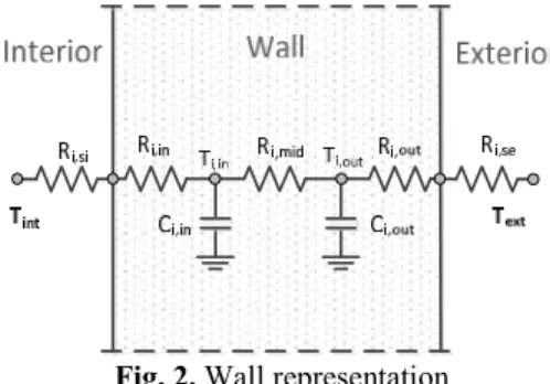
Fig. 2. Wall representation
Based on the detailed physical description, the wall dynamic can be described using the
analogy with the electric components. As shown in [12] the wall can be described by a 3R-2C model (3 resistors and 2 capacitors). The wall is schematically represented in figure 2.
In the model i represent the building element index. The following notations are used: R the thermal resistance, C thermal capacity and T describe the temperature.
The parameters used in the model are computed with the following relations:
Ri,in=Ri,mid=Ri,out=1/3Ri (8) Ci,in=Ci,out=1/2Ci. (9)
For 3R-2C model two differential equations can be written. The equations that model the wall are:
, , = ,
, , +
, ,
, (10)
, , = ,
, , +
, ,
, (11)
For windows, the heat capacity of the element is not taken in account. In this case only the heat resistance is used to evaluate the heat flow through this type of building element.
=( ) (12)
The equation 12 expresses the heat flow that cause heat loses through windows.
2.3Heat flow caused by ventilation
The ventilation heat loss is caused by the direct movement of hot air out of the build due to intentional ventilation or air exchange through the building cracks or gaps in the walls. For winds less than 5 [m/s] the effect from draught effects are of minor importance [13]. Further only the influence of the intentional ventilation will be considered in the model.
The heat loses by ventilation can be described using eq. 13:
= ∙ ( − ) (13)
2.4Model of building heat sources
The most important elements that produce heat inside the building are the heating systems and the sun light effect on the building. The model can also take in account the effect of the people inside the building and the effect of different electrical devices that generate heat depending of the simulation purposes and building type. In this paper only the external influence of the solar radiation is taken in account.
The solar radiation transmitted through the windows will affect the air and stuff temperatures inside the room and also the floor temperature. So a fraction p from solar radiation qs is transmitted to the floor and a fraction (1-p) is transmitted to the air and stuff inside the room. The contribution from solar radiation is model as:
, = (1 − ) ∙
, = ∙ ∙ (14)
In eq. 14 the parameter I represents the solar radiation and Aw represents the window area. For calculation only 60% of the measured window size is used [14]. This denotes that only a fraction of solar radiation pass through the window, the other part is absorbed or reflected.
2.5Dynamic model for one room
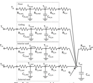
The thermal dynamic model of one room includes the dynamics of the internal elements, the heat sources and the heat flow that exist through all construction elements that confined the room.
For the system presented in figure 3, nine differential equations can be written. For walls, floor and ceiling the dynamics is define by equations 10 and 11. The following temperatures are used: Tg – ground temperature, Ta – attic temperature, Text – external temperature, Trx – neighbor room temperature.
The dynamic behavior of the room internal environment is described by eq. 15:
=( )+ ∑ ,
, , + (15)
where - represent the thermal capacitance of all internal elements
- the temperature inside the room - the temperature of exterior environment
- heat sources that affect the room thermal dynamics.
The thermal capacity Cint of the internal elements consists of the internal air thermal capacity plus the thermal capacity of all things inside the room.
Floor Ceiling External wall R1,in R1,mid R1,out C1,in C1,out Tint
Text T1,out T1,in
Ta Tg R2,in R3,in T2,in T3,in R2,mid R3,mid R2,out R3,out T2,out T3,out Cint C2,in C3,in C2,out C3,out Text Rwin qj Interior wall Trx R4,in T4,in R4,mid R4,out T4,out C4,in C4,out R4,si R3,si R2,si R1,si
Fig. 3. One room model representation
For computing the air capacity eq. 16 is used:
= ∙ (16)
where is the volumetric heat capacity of air and is the room volume.
The heat capacity of the “stuff” inside the room (furniture, belongings etc.) can be computed by approximating the specific heat capacity of all objects inside the room and their total mass.
3. CASE STUDY
Fig. 4. Building 3D CAD model
For calculating the geometrical parameters, the building sketch (Fig.5) is used of each room. The height of the rooms is 2.8 [m].
Fig. 5. Building sketch
The obtained geometrical parameters for the construction elements inside the building are given in Table 1.
Table.1 Building dimensional parameters Constructio
n element area
Roo m [m2]
Kitche n [m2]
Hallway [m2]
Bathro om[m2]
Exterior wall 43,96 32.64 5.6 5.6 Interior wall 15,4 15.4 24.64 16.8 Ceiling 28,5 15.95 6.8 4
Floor 28,5 15.95 6.8 4
Windows 3.52 2.64 - 0.44
It is consider that the exterior wall in all rooms have the same composition, the same is assumed for the interior walls, floor and ceiling. In order to simulate the building dynamics the thermal resistance and thermal capacity parameters for each construction element must be determined. The parameters can be calculated from the building plans or estimated them from measured building data [15].
In this work the parameters for the construction elements were calculated from using building plan and the guidelines form [11]. Table 2 presents the unitary parameters Ri,unit and Ci,unit that were calculated for the construction elements of the building. The Ri,unit values includes also the radiation and convection phenomena.
Tabel 2. Bulding construction elements parameters Parameter Ri,unit
[m2K /W]
Ci,unit
[J/( m2K)] Exterior wall 3.772 2.955x10⁵ Interior wall 0,833 1.345x10⁵
Ceiling 2.737 3.98x10⁵
Floor 4,003 5.506x10⁵
Windows 0,43 -
For each room the analytical model was developed, and the differential equations were implemented in the simulation environment Matlab/Simulink.
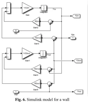
Figure 6 presents the Simulink model for a building wall as result of implementing the equation 10 and 11. The inputs are the interior Tint and the exterior Text temperatures. The wall temperature Tin is used further for calculation the internal thermal dynamics of the room.
Fig. 6. Simulink model for a wall .
dynamic of the room internal environment and the heat fluxes produced by the Sun radiation, ventilation and windows heat loses. In figure 7 the Simulink model obtained for the building room is presented. Similar models were developed for all 4 building rooms.
Fig. 7. Simulink model for one room
Using the obtained model a sets of simulations were conducted. The numerical results were obtained using the Matlab Ode45 solver.
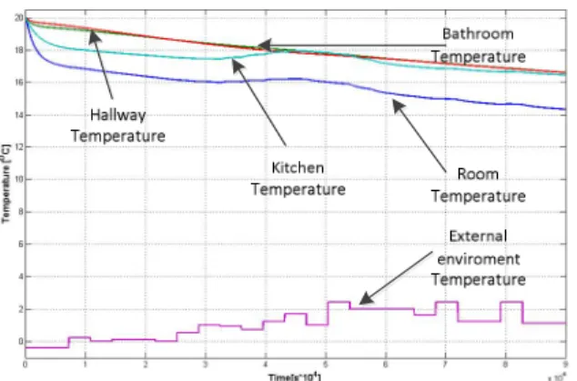
In the simulations no internal heating source is used. The building dynamics is influenced only by the changes from the external environment (air and soil temperature, solar radiation). For the variation of the external environment parameters a set of measured data from Cluj-Napoca city were used. The values are measured in January hourly for a period of 24 hours. The earth temperature during this month is about 2 [ºC]. The external environment data used in the simulation are presented in figure 8.
Fig. 8. External environment parameters
In the developed experiments the initial temperature in all rooms is 20 [ºC]. The experiments are conducted for 24 hours period of time. In the simulation the building orientation is taking in account, this will affect the sun influence on the building rooms.
In figure 9 the variation of the room temperature and the estimated temperature values inside the exterior wall are presented. On important aspect that influences the simulation results is the initialization of the temperatures in all building construction elements.
Fig. 9. Simulation results
house compared with the ones that have windows on the north side.
Fig. 10. Simulation results – rooms temperature variation
Other heat sources can be easily added to the model, in this way the influence of people inside the building and the effect of different electrical devices that generate heat can be tested.
The analytical form of the model offers the possibility to evaluate multiple parameters that influence the thermal behavior of the building (temperatures, heat flows, heat gains, the influence of thermal capacity of the construction elements etc.). These parameters are important in testing process of the Building Energy Management Systems; the parameters are used for evaluating the current state of the controlled building and to calculate the optimal heating solution for the process.
4. CONCLUSION
The paper presents the development of a multi room building thermo dynamic model. The model was developed and evaluated from the perspectives of using it in the design process of energy management systems. The obtained analytical model was tested by modeling a 4 rooms building. The obtained results validated the model capability for the use in the development of energy management systems. The ability to determine different thermic parameters in the building facilitate the development of complex experiment that can use the model for testing or optimization process of BEMS systems.
The model offers also good perspective for the use in advanced control algorithms which use the dynamic model of the building.
5. ACKNOWLEDGMENT
This paper was supported by the Post-Doctoral Programme POSDRU/159/ 1.5/S/137516, project co-funded from European Social Fund through the Human Resources Sectorial Operational Program 2007-2013.
6. REFERENCES
[1]L. Perez-Lombard, J. Ortiz, C. Pout, A review on buildings energy consumptions, Journal Energy and Buildings 40:3 (2008) 294-298.
[2]Information on
http://ec.europa.eu/europe2020/targets/eu-targets/ - Objectives of Europe 2020 Strategy. [3]Shaikh, P., Nor, N., Nallagownden, P.,
Elamvazuthi, I., Ibrahim, T., “A review on optimized control systems for building energy and comfort management of smart sustainable buildings”, Journal Renewable and Sustainable Energy Reviews, Vol. 31, pp. 409-429, 2014. [4] Balan, R., Stan, S., Lapusan, C., A model based
predictive control algorithm for building
temperature control, Proceedings of The 3rd
IEEE International Conference on Digital Ecosystems and Technologies, 2009. DEST'09, pp. 540-545, 2009.
[5]Lapusan,C., Balan, R., Hancu, O., Rad, C., "Rapid Control Prototyping in the Development of Home Energy Management Systems, The 6th international conference on advanced concepts in mechanical engeneering, Publised in Applied Mechanics and Material, pp. 395-400 2014. [6]Kramer, R., Schijndel, J., Schellen, H.,
Simplified thermal and hygric building models:
A literature review, Frontiers of Architectural
Research, Volume 1, Issue 4, December, pp. 318-3252012.
[7]Candanedo, J, Dehkordi, V., Phylroy, L., A control-oriented simplified building modelling
strategy, The 13th International Conference of
the International Building Performance Simulation Association, France, 25-30 August, 2014.
[8]Balan, R., Hancu, O., Stan, S., Lapusan, C., Donca, R., Application of a Model Based Predictive Control Algorithm for Building
Temperature Control, Proceedings of the 3rd
Saving, Environmental Education, pp.97-101, 2009.
[9] Lapusan, C., Maties, V., Balan, R., Hancu O., “ Modeling and simulation methods for designing mechatronic systems ”, Journal of engineering Studies and Research, Vol. 16, pp. 20-24, 2010. [10]Achterbosch, G., Jong, P., Krist-Spit, C., van
der Meulen C, Verberne, J., “The Development of a Convenient Thermal Dynamic Building Model”, Journal Energy and Buildings, Vol 8, pp. 183-196, 1985
[11]Normative - Thermo technical regulations regarding calculation of the Elements of
Building Construction-Indicative C107-2005.
[12]Xinhau, X., phd thesis, Model Based Building
Performance. Evaluating and Diagnosis, Hong
Kong Polytechnic University, 2005.
[13]Etheridge, D, Nevrala, D, Air Infiltration in the U.K. and its Impact on the ThermalEnviroment,
Brithis Gas Corporation, London, 1978.
[14] Andersen, K., Madsen, H., Hansen, L.,
Modeling the heat dynamics of buildings using
stochastic differential equations, Journal Energy
and Buildings,Vol 31, pp. 13-24, 2000.
[15] Balan, A., Donca, R., Lapusan, C., Draghici, M., Balan, R., Smart Metering and Control for
Home Energy Efficiency, Proceedings of The
11th REHVA World Congress and the 8th International Conference on Indoor, Air Quality, Ventilation and Energy Conservation in Buildings, pp. 3115-3124, Prague, Czech Republic, 2013.
DEZVOLTAREA UNUI MODEL TERMIC AL UNEI CLADIRI CU MAI MULTE CAMERE PENTRU UTILIZAREA IN PROCESUL DE PROIECTARE A SISTEMELE DE MANAGEMENT ENERGETIC
Rezumat: Pentru a satisface nevoile tot mai mari în ceea ce privește eficiența și protecția mediului, sistemele de management energetic al clădirilor integrează în structura lor algoritmi de control din ce în ce mai complecși si rețele inteligente de senzori. Pentru a putea dezvolta un astfel de sistem este necesară existenta unor modele dinamice adecvate ale clădirii, modele ce sunt folosite atât de algoritmii de control cât și în faza de testarea și optimizare în procesul de proiectare. In aceasta lucrare se prezintă dezvoltarea unui model dinamic al unei clădiri cu mai multe încăperi, model ce poate fi utilizat în procesul de dezvoltare a sistemelor de management energetic al clădirilor. Modelul propus este testat prin dezvoltare in mediul Matlab/Simulink a unui model pentru o clădire cu 4 încăperi.
Ciprian LAPUSAN, dr. eng., Technical University of Cluj-Napoca – Department of Mechatronics and Machine Dynamics, [email protected]
Radu BALAN, dr. eng., Technical University of Cluj-Napoca – Department of Mechatronics and Machine Dynamics, [email protected]
Ciprian RAD, dr. eng., Technical University of Cluj-Napoca – Department of Mechatronics and Machine Dynamics, [email protected]
![Fig. 8. External environment parameters In the developed experiments the initial temperature in all rooms is 20 [ºC]](https://thumb-us.123doks.com/thumbv2/123dok_us/8000303.2121018/6.918.109.419.248.697/external-environment-parameters-developed-experiments-initial-temperature-rooms.webp)