Exploiting Task-level Concurrency in
a Programmable Network Interface
Hyong-youb Kim, Vijay S. Pai, and Scott Rixner
Rice University
hykim, vijaypai, [email protected]
ABSTRACT
Programmable network interfaces provide the potential to extend the functionality of network services but lead to instruction pro-cessing overheads when compared to application-specific network interfaces. This paper aims to offset those performance disadvan-tages by exploiting task-level concurrency in the workload to par-allelize the network interface firmware for a programmable con-troller with two processors. By carefully partitioning the handler procedures that process various events related to the progress of a packet, the system can minimize sharing, achieve load balance, and efficiently utilize on-chip storage. Compared to the unipro-cessor firmware released by the manufacturer, the parallelized net-work interface firmware increases throughput by 65% for tional UDP traffic of maximum-sized packets, 157% for bidirec-tional UDP traffic of minimum-sized packets, and 32–107% for real network services. This parallelization results in performance within 10–20% of a modern ASIC-based network interface for real network services.
Categories and Subject Descriptors
D.1.3 [Programming Techniques]: Concurrent Programming – Parallel Programming
General Terms
Experimentation, Performance
Keywords
Programmable Network Interface, Parallel Programming, Ethernet, Firmware
1.
INTRODUCTION
Modern computer systems access the network through a net-work interface card (NIC). The NIC implements the protocols of This work is supported in part by a donation from Advanced Mi-cro Devices and by the National Science Foundation under Grant No. CCR-0209174.
Permission to make digital or hard copies of all or part of this work for personal or classroom use is granted without fee provided that copies are not made or distributed for profit or commercial advantage and that copies bear this notice and the full citation on the first page. To copy otherwise, to republish, to post on servers or to redistribute to lists, requires prior specific permission and/or a fee.
PPoPP’03, June 11–13, 2003, San Diego, California, USA.
Copyright 2003 ACM 1-58113-588-2/03/0006 ...$5.00.
the physical medium, typically an Ethernet cable, and frees the op-erating system from directly sending and receiving data over that medium. Instead, the operating system stores and retrieves data from the system memory and communicates with the NIC over the local interconnect, typically a peripheral component interconnect (PCI) bus. The functionality of such a PCI-based Ethernet NIC is fixed and well-defined, so most modern NICs use an application-specific integrated circuit (ASIC) controller to store and forward data between the PCI bus and the Ethernet. A programmable con-troller on the NIC, however, provides the flexibility to improve and modify the functionality of the NIC. This is extremely valu-able in improving network server performance by enabling critical processing or frequently accessed data to be moved closer to the network, as in iSCSI [13] or network interface data caching [7].
The Tigon programmable Ethernet controller, released in 1997, is used in a family of 3Com Gigabit NICs. The Tigon includes two MIPS R4000-based processors, but the firmware that has been released by the manufacturer only utilizes a single processor. Ex-periments show that using this firmware, the Tigon is unable to match the performance of modern ASIC controllers. Furthermore, the limited power distribution and cooling area available to a PCI card restrict the clock speed of any processor on a PCI card, so it is impractical to implement a single-processor programmable NIC controller with sufficient performance to support the wire speed of the Ethernet cable. However, effective utilization of multiple pro-cessors can provide the same performance as a single processor running at a faster clock speed while consuming far less power [9]. Fortunately, there is abundant parallelism in network interface processing. This paper explores the parallelization of the Tigon firmware across the two processors. The Tigon provides sev-eral mechanisms to enable efficient event-driven firmware. The event-driven organization allows the processing of multiple net-work packets to be overlapped with each other as well as with high latency operations, such as data transfers between the host and NIC. Successfully parallelizing event-driven firmware across multiple processors requires partitioning the event handlers while balancing the workload and minimizing sharing of data and hard-ware resources. This paper presents a static partition of event han-dlers that minimizes hardware resource sharing and requires only three shared variables. Further, this partitioning of event handlers enables better utilization of the on-chip memory associated with each processor. Parallelizing the network interface firmware in this fashion increases throughput by 65% for bidirectional UDP fic of maximum-sized packets, 157% for bidirectional UDP traf-fic of minimum-sized packets, and 32–107% for real network ser-vices. This parallelization results in performance within 10–20% of a modern ASIC-based NIC for real network services.
ex-Host
CPU
Main Memory
Local
Interconnect
NIC
BufferNetwork
5 2 6 Packet 3 Packet Descriptor Buffer DescriptorBridge
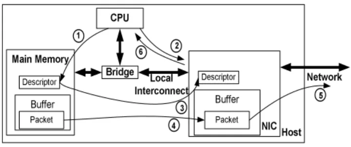
1 4Figure 1: Steps involved in sending a packet.
plains the functionality of a network interface. Section 3 describes how the Tigon hardware mechanisms and firmware implement a network interface. Section 4 then describes the proposed paral-lelization of network interface firmware for the Tigon. Section 5 describes the experimental methodology used in this study, and Section 6 analyzes the experimental results. Section 7 discusses the issues in scaling to more than two processors, and Section 8 relates this work to earlier work. Section 9 summarizes the paper.
2.
NETWORK INTERFACE
FUNCTION-ALITY
The host operating system uses the network interface to send and receive packets. The operating system stores and retrieves data directly to or from the main memory, and the NIC transfers this data to or from its own local transmit and receive buffers. Sending and receiving data is handled cooperatively by the NIC and the device driver in the operating system, which notify each other when data is ready to be sent or has just been received.
Sending a packet requires the steps shown in Figure 1. In step 1, the device driver first creates a buffer descriptor, which contains the starting memory address and length of the packet that is to be sent, along with additional flags to specify options or commands. If a packet consists of multiple discontiguous regions of memory, the device driver creates multiple buffer descriptors. The device driver then writes to a memory-mapped register on the NIC with infor-mation about the new buffer descriptors, in step 2. In step 3 of the figure, the NIC initiates one or more direct memory access (DMA) transfers to retrieve the descriptors. Then, in step 4, the NIC ini-tiates one or more DMA transfers to move the actual packet data from the main memory into its transmit buffer using the address and length information in the buffer descriptors. After the packet is transferred, the NIC sends the packet out onto the network through its medium access control (MAC) unit in step 5. The MAC unit is responsible for implementing the link-level protocol for the under-lying network such as Ethernet. Finally, in step 6, the NIC informs the device driver that the descriptor has been processed, possibly by interrupting the CPU.
Receiving packets is different, since the system can anticipate neither when packets will arrive on the network nor the size of arriving packets. Therefore, the device driver must pre-allocate a pool of main memory buffers ahead of time to hold maximum-sized network packets that may be received in the future. As these buffers are consumed, the device driver must continually allocate new buffers for subsequent packets and create buffer descriptors that store information about those buffers. The device driver noti-fies the NIC that new buffer descriptors are available, and the NIC retrieves them for later use, following steps 1 through 3 of Figure 1. Figure 2 depicts the steps for receiving a packet from the
net-Host
CPU
Main Memory
Local
Interconnect
NIC
BufferNetwork
1 2 4 Packet 3 Packet Descriptor Buffer DescriptorBridge
Figure 2: Steps involved in receiving a packet.
Tigon CPU A CPU B Scratch Pad Scratch Pad External SRAM Read DMA Write DMA MAC Memory Bus Arbiter PCI Interface
PCI Full-duplex Gigabit Ethernet Interface
Memory Bus
Figure 3: A block diagram of the Tigon controller.
work into these pre-allocated receive buffers. In step 1, a packet arriving over the network is received by the MAC unit and stored in the NIC’s local receive buffer. In step 2, the NIC initiates a DMA transfer of the packet into a pre-allocated main memory buffer. In step 3, the NIC produces a buffer descriptor with the resulting ad-dress and length of the received packet and initiates a DMA transfer of the descriptor to the main memory, where it can be accessed by the device driver. Finally, in step 4, the NIC notifies the device driver about the new packet and descriptor, typically through an in-terrupt. The device driver may then check the number of unused receive buffers in the main memory and replenish the pool for fu-ture packets.
3.
A PROGRAMMABLE NETWORK
IN-TERFACE
A programmable network interface implements the operations described in Section 2 by executing firmware code on one or more programmable processors. The Tigon is one representative pro-grammable Ethernet controller that provides several mechanisms to support parallel and event-driven firmware.
3.1
Tigon Hardware Mechanisms
The Tigon programmable Ethernet controller supports a PCI host interface and a full-duplex Gigabit Ethernet interface. Fig-ure 3 shows a block diagram of the Tigon. The Tigon has two 88 MHz MIPS R4000-based single-issue, in-order embedded pro-cessors which share access to external SRAM. Each processor has a one-line (64-byte) instruction cache to capture spatial locality for instructions from the SRAM.
Time
EventsS4:
Fetch the packet to the transmit bufferS5:
Transmit the packet Packet #1 (send)R2:
Transfer the packet to a host buffer Packet #2(receive)
R3:
host device Informdriver of new packet Data arrives
from network completionDMA completionDMA
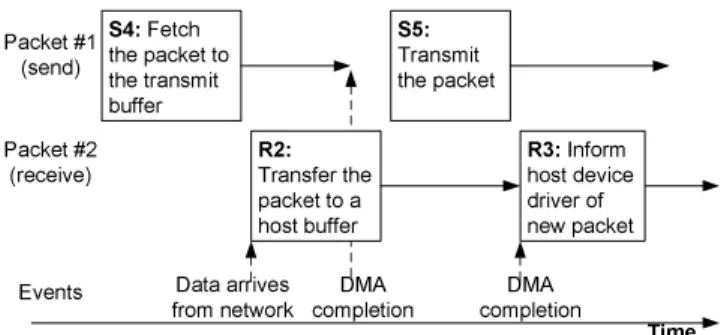
Figure 4: Illustration of overlapped execution of the send and receive steps in Figures 1 and 2. Asynchronous events allow the firmware to overlap the execution of multiple steps of send and receive processing.
In the Tigon, each processor also has a private on-chip scratch
pad memory, which serves as a low-latency software-managed
cache. The scratch pads behave differently from coherent caches because the code running on the Tigon is solely responsible for ex-plicitly writing, using, and managing their contents. The scratch pads, external SRAM, and other hardware registers are all mapped onto different memory address regions and form the Tigon memory address space. Thus, a processor accesses its scratch pad through ordinary load and store instructions, giving the firmware complete control over the use of the scratch pads. For instance, the firmware may use the scratch pads to store frequently-accessed code re-gions or private data for low-latency memory access. However, the scratch pads provide no coherence mechanism, so shared data is stored in the shared external SRAM.
Hardware DMA and MAC controllers enable the firmware to transfer data to and from the system’s main memory and the net-work, respectively. The DMA controller provides separate read and write channels, each with an associated queue of DMA descrip-tors. Each DMA descriptor contains enough information to initiate one DMA transfer (such as host memory address, local SRAM ad-dress, and length). The PCI bus can only support one transfer at a time, so the DMA controller serializes the transfers pending in these queues. Similarly, the MAC unit provides separate transmit and receive channels, each with a queue of MAC descriptors that contain information about packets to be transmitted or that have been received. However, Ethernet is full-duplex, so one send and one receive can occur simultaneously.
The Tigon provides three special-purpose memory-mapped reg-isters to facilitate parallelization: a hardware semaphore register and an event register for each processor. The hardware semaphore register provides support for a single lock. The standard MIPS synchronization instructions (load-linked and store-conditional) are not supported, but additional locks can be implemented in soft-ware using the hardsoft-ware semaphore. The event registers provide an efficient event notification mechanism to support event-driven firmware. Each bit in the event registers corresponds to a particular event; when a bit is set, it signifies that the event has occurred and has not yet been handled. The Tigon hardware reserves a number of bits for predefined hardware-generated events, and the firmware can use the rest of the bits for firmware-generated events.
The hardware event mechanisms and descriptor queues of the Tigon enable firmware to efficiently handle multiple packets in transit and to overlap long latency operations, like DMA transfers, with other processing. For example, Figure 4 illustrates some of the processing for two packets; the numbers in the blocks correspond to
the send and receive steps in Figures 1 and 2. The first block in the figure corresponds to step 4 in sending packet #1, which initiates a DMA transfer of the packet. Rather than waiting for the DMA transfer to complete, the code for this block enqueues the appropri-ate DMA descriptor to the DMA controller and yields control to the event dispatch loop. While packet #1 is being transferred, packet #2 arrives from the network. The firmware then enqueues a DMA write to transfer the received data to the main memory.
During the processing of step R2, the DMA for packet #1 com-pletes. Unlike the asynchronous event notification mechanisms found in most operating systems, events in the Tigon do not in-terrupt firmware execution. Once an event handler is invoked, it is run to completion, even if higher priority events occur. So, the NIC does not handle step S5 until the processing for step R2 completes. At that point, the NIC may transmit the packet. Finally, when the DMA write completes for packet #2, the NIC must inform the de-vice driver of the new packet in the main memory.
3.2
Released Tigon Firmware
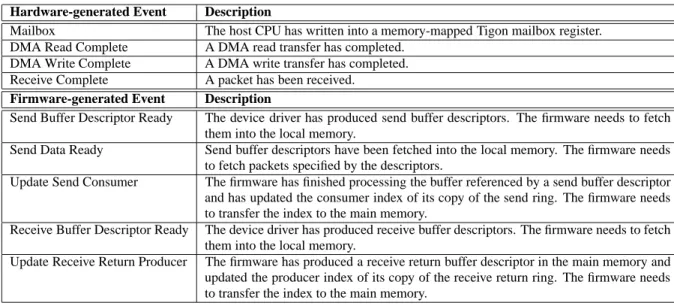
Alteon Websystems released several versions of the Tigon firmware as open-source software [1]. This released firmware is event-driven, consisting of an event dispatch loop and a set of event handlers. The event dispatch loop prioritizes events according to the order of the corresponding bits in the event register. If no bits are set, the event dispatch loop repeatedly polls the event register until an event occurs. Table 1 describes the hardware-generated and firmware-generated events used by the firmware to send and receive packets.
The firmware defines three types of buffer descriptors: send for packets to be sent, receive for buffers in the main memory into which the NIC may store received packets, and receive return for received packets after they are stored in the main memory. Send and receive descriptors are produced by the host device driver and consumed by the NIC, while receive return descriptors are pro-duced by the NIC and consumed by the host device driver. The firmware and device driver cooperatively store the three types of buffer descriptors in three separate ring structures. Each ring is a circular buffer with producer and consumer indices that enable the device driver and NIC to inform each other when they have pro-duced or consumed buffer descriptors. The device driver and NIC both store copies of each ring in their own memories; these copies are kept consistent through DMA transfers. These DMA transfers may be delayed arbitrarily, but inconsistencies are allowed as long as each copy maintains the producer/consumer relationship both locally and with respect to the other copy.
The high level steps of send and receive processing described in Section 2 are implemented through multiple events. Sending a packet specifically consists of the following sequence of events:
1. Mailbox – Read the producer index of the device driver’s copy of the send buffer descriptor ring from a mailbox register. Raise the Send Buffer Descriptor Ready event.
2. Send Buffer Descriptor Ready – Enqueue a DMA descriptor to transfer the newly produced buffer descriptor(s).
3. DMA Read Complete – Determine that the completed DMA has transferred send buffer descriptors. Update the producer in-dex of the firmware’s send ring based on the number of fetched descriptors. Raise the Send Data Ready event.
4. Send Data Ready – Enqueue one or more DMA descriptors to transfer a packet into the transmit buffer. Also enqueue a MAC descriptor to inform the MAC to transmit the packet when it arrives in the transmit buffer.
Hardware-generated Event Description
Mailbox The host CPU has written into a memory-mapped Tigon mailbox register. DMA Read Complete A DMA read transfer has completed.
DMA Write Complete A DMA write transfer has completed. Receive Complete A packet has been received.
Firmware-generated Event Description
Send Buffer Descriptor Ready The device driver has produced send buffer descriptors. The firmware needs to fetch them into the local memory.
Send Data Ready Send buffer descriptors have been fetched into the local memory. The firmware needs to fetch packets specified by the descriptors.
Update Send Consumer The firmware has finished processing the buffer referenced by a send buffer descriptor and has updated the consumer index of its copy of the send ring. The firmware needs to transfer the index to the main memory.
Receive Buffer Descriptor Ready The device driver has produced receive buffer descriptors. The firmware needs to fetch them into the local memory.
Update Receive Return Producer The firmware has produced a receive return buffer descriptor in the main memory and updated the producer index of its copy of the receive return ring. The firmware needs to transfer the index to the main memory.
Table 1: Hardware-generated and firmware-generated events in the Tigon for send and receive processing.
5. DMA Read Complete – Determine that the completed DMA has transferred packet data. Update the consumer index of the firmware’s send ring. If the number of send descriptors consumed is greater than the interrupt coalescing threshold, raise the Update Send Consumer event.
6. Update Send Consumer – Enqueue a DMA descriptor to trans-fer the consumer index of the send ring to the host.
7. DMA Write Complete – Determine that the completed DMA has transferred the consumer index. Interrupt the host CPU. The pre-allocation of main memory buffers for future received packets follows steps 1–3 above, but using the receive ring and Re-ceive Buffer Descriptor Ready. Steps 4 and 5 are eliminated, as there is no data to fetch. Transferring the consumer index is also not needed, as it is stored as a field of the receive return buffer de-scriptors that are produced by the NIC. For the receive return ring, the firmware only maintains its producer index because the device driver ensures that the receive return ring is never full when the re-ceive ring is not full. The actual rere-ceive into pre-allocated main memory buffers consists of:
1. Receive Complete – Enqueue a DMA descriptor to transfer the packet into the buffer described by the next buffer descriptor in the receive ring. Also create a receive return buffer descriptor with information about the packet, and enqueue a DMA descriptor to transfer the new buffer descriptor. If the number of receive re-turn descriptors produced is greater than the interrupt coalescing threshold, raise the Update Receive Return Producer event.
2. Update Receive Return Producer – Enqueue a DMA descrip-tor to transfer the new producer index of the receive return buffer descriptor ring.
3. DMA Write Complete – Determine that the packet has been transferred to the host. No action is needed.
4. DMA Write Complete – Determine that the receive return buffer descriptor has been transferred to the host. No action is needed.
5. DMA Write Complete – Determine that the producer index of the receive return ring has been transferred to the host. Interrupt the host CPU.
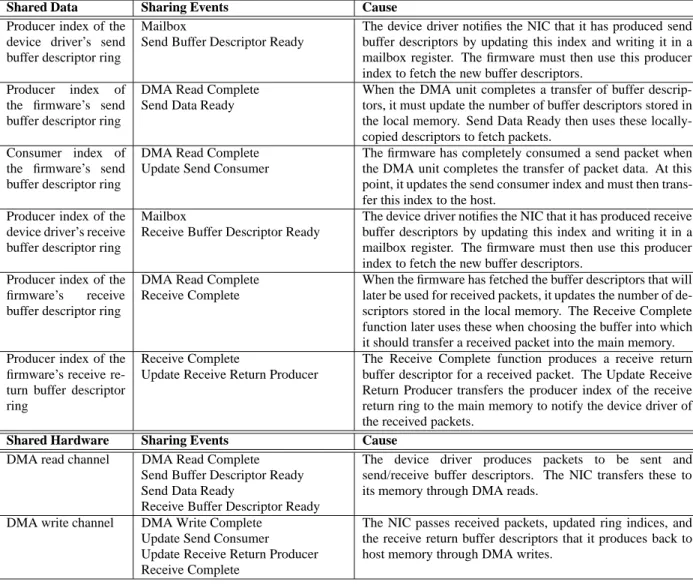
The various events used to send and receive packets must share certain data structures to maintain global state information. The events also share hardware resources that are explicitly managed by the firmware, such as DMA channels. Table 2 lists the data and explicitly-managed hardware resources shared by the event handlers and the cause of sharing in the released firmware. Data is typically shared by subsequent steps in the send or receive se-quence, or between the last step in transferring descriptors for the pre-allocated main memory buffers and the first step in the actual receive. Events related to sending or pre-allocating main memory buffers share the read DMA channel, while the write DMA chan-nel is primarily shared among events related to the actual receive process. The only exception is that Update Send Consumer also requires the write DMA channel. The MAC channels are also ex-plicitly managed by the firmware, but they are not shared among any events. The receive channel acts as the source of packets arriv-ing from the network, so only the Receive Complete event needs to access the channel in order to dequeue received packets. Packets are sent out over the network using the transmit channel, and no further action is required after each packet is transmitted. There-fore, only the Send Data Ready event needs to access the channel in order to enqueue packet transmissions.
4.
PARALLELIZATION OF FIRMWARE
Utilizing both processors efficiently is difficult because of the data and resource sharing described in the previous section. The released firmware for the Tigon only makes use of a single proces-sor, likely due to the difficulty of parallelization. However, a single 88 MHz processor is not sufficient to process bidirectional traffic at rates comparable to modern ASIC-based NICs. For example, a NIC using this firmware achieves a maximum throughput of 938 Mb/s on bidirectional UDP traffic consisting of maximum-sized frames, whereas a modern ASIC-based NIC delivers a maximum through-put of 1882 Mb/s on the same workload. Furthermore, the limited cooling area and power distribution available to a PCI card con-strain the clock speed of any processor on the card, so performance cannot be gained by simply increasing operating frequency. There-fore, the firmware must be parallelized across multiple processors in order to approach the performance of special-purpose NICs.
Shared Data Sharing Events Cause Producer index of the
device driver’s send buffer descriptor ring
Mailbox
Send Buffer Descriptor Ready
The device driver notifies the NIC that it has produced send buffer descriptors by updating this index and writing it in a mailbox register. The firmware must then use this producer index to fetch the new buffer descriptors.
Producer index of the firmware’s send buffer descriptor ring
DMA Read Complete Send Data Ready
When the DMA unit completes a transfer of buffer descrip-tors, it must update the number of buffer descriptors stored in the local memory. Send Data Ready then uses these locally-copied descriptors to fetch packets.
Consumer index of the firmware’s send buffer descriptor ring
DMA Read Complete Update Send Consumer
The firmware has completely consumed a send packet when the DMA unit completes the transfer of packet data. At this point, it updates the send consumer index and must then trans-fer this index to the host.
Producer index of the device driver’s receive buffer descriptor ring
Mailbox
Receive Buffer Descriptor Ready
The device driver notifies the NIC that it has produced receive buffer descriptors by updating this index and writing it in a mailbox register. The firmware must then use this producer index to fetch the new buffer descriptors.
Producer index of the firmware’s receive buffer descriptor ring
DMA Read Complete Receive Complete
When the firmware has fetched the buffer descriptors that will later be used for received packets, it updates the number of de-scriptors stored in the local memory. The Receive Complete function later uses these when choosing the buffer into which it should transfer a received packet into the main memory. Producer index of the
firmware’s receive re-turn buffer descriptor ring
Receive Complete
Update Receive Return Producer
The Receive Complete function produces a receive return buffer descriptor for a received packet. The Update Receive Return Producer transfers the producer index of the receive return ring to the main memory to notify the device driver of the received packets.
Shared Hardware Sharing Events Cause
DMA read channel DMA Read Complete Send Buffer Descriptor Ready Send Data Ready
Receive Buffer Descriptor Ready
The device driver produces packets to be sent and send/receive buffer descriptors. The NIC transfers these to its memory through DMA reads.
DMA write channel DMA Write Complete Update Send Consumer Update Receive Return Producer Receive Complete
The NIC passes received packets, updated ring indices, and the receive return buffer descriptors that it produces back to host memory through DMA writes.
Table 2: List of data objects and explicitly-managed hardware resources shared among the various events in the released firmware.
4.1
Parallelization Concepts
Effective parallelization requires identifying the concurrent tasks, partitioning those tasks among processing elements for load balance, and avoiding sharing of data or hardware resources be-tween processing elements. In an event-driven system like the Tigon firmware, the fundamental unit of concurrency is an event handler. Thus to exploit parallelism, the events may be partitioned and assigned to specific processors.
However, partitioning event handlers across the processors may require synchronization. As described in Section 3.1, event han-dlers always run to completion without being interrupted. Thus, sharing of data or hardware resources between event handlers that always run on the same processor requires no synchronization. An effective partition should consider the sharing patterns described in Table 2 and place events that share data or resources on the same processor whenever possible in order to reduce sharing across the processors.
Some forms of parallelization may enable better use of the Tigon hardware mechanisms. For example, data that is exclusively used by one processor may be placed in that processor’s private scratch pad, allowing much faster access than the external SRAM. Further,
the firmware code can also be partitioned across two processors and stored in their respective scratch pads.
Finally, the cooperation between the firmware and the device driver provides additional support for parallelization. In particu-lar, a firmware operation that impedes parallelization may simply be eliminated if the host device driver can implement it efficiently instead.
4.2
Parallelization Strategy
Figure 5 profiles the execution time of the event handlers in the released firmware for a workload consisting of simultaneous sends and receives of minimum-sized (64-byte) Ethernet frames. The send and receive rates are equal and are chosen such that no packets are dropped by the Tigon. The Y axis shows the events. The X axis shows the processor execution time consumed for each event han-dler as a fraction of the total execution time of all send and receive events. The scratch pads are disabled during the measurement to eliminate any bias for the particular subset of code and data that the Tigon manufacturers chose to place in the scratch pad for the released firmware.
The Send Data Ready and Receive Complete handlers clearly dominate execution time at roughly 30% each. Among the other
10 20 30
Normalized Execution Time of Event Handler (%) Update Send Consumer
Send Buffer Descriptor Ready Receive Buffer Descriptor Ready Update Receive Return Producer DMA Write Complete Mailbox DMA Read Complete Receive Complete Send Data Ready
Figure 5: Execution time of event handlers normalized to total execution time of all send and receive events.
event handlers, DMA Read Complete is the next largest at 14%. It is over twice as expensive as the DMA Write Complete handler be-cause the DMA Read Complete handler uses the newly read data to initiate other actions. Each of the other handlers consumes 4–6% of the total, except for Update Send Consumer as the least significant at 0.6%.
Since they collectively account for 60% of the execution time, a static partition of event handlers for this workload should place Receive Complete and Send Data Ready on separate processors in order to balance the load on the processors. The other event han-dlers should be selected based on both load balance and the sharing patterns shown in Table 2. DMA Read Complete shares data with both of the dominant event handlers, but only shares explicitly-managed hardware with Send Data Ready. Thus, DMA Read Com-plete should be colocated with Send Data Ready. However, assign-ing these two events to the same processor is only valuable if it eliminates synchronization for this hardware resource—the DMA read channel. Thus, Send Buffer Descriptor Ready and Receive Buffer Descriptor Ready should also be put on the same processor. Both of these handlers share data with Mailbox, but placing that handler on the same processor would push this processor’s load well above 50% of the total. DMA Write Complete shares no data with any other event, but should be placed on the same processor as Receive Complete since they share an explicitly-managed hard-ware resource. Update Receive Return Producer shares both data and hardware with Receive Complete, and thus should be placed on the same processor.
The only remaining handler is the least significant, Update Send Consumer. It shares data with DMA Read Complete but shares the DMA write channel with the handlers on the other processor. To resolve this conflict, the Update Send Consumer handler is modi-fied to update only the local copy of the send ring consumer index without transferring it to the main memory using DMA. Instead, the device driver is modified to read this index through memory-mapped I/O. This eliminates sharing of the DMA write channel, thus allowing Update Send Consumer to be colocated with DMA Read Complete.
The only examples of interprocessor sharing resulting from the above partition are the data sharing between the DMA Read Complete and the Receive Complete handlers and the data shar-ing between the Mailbox and the Send/Receive Buffer Descriptor Ready handlers; there is no interprocessor sharing of the
explicitly-managed hardware resources shown in Table 2. The only shared variables are the producer indices for the driver’s send buffer de-scriptor ring and for both copies of the receive buffer dede-scriptor ring. All other variables may be placed in the scratch pads. The sharing pattern of each shared variable is such that only one han-dler writes it and the reader may read an old value without causing any correctness problems. Consequently, these variables may be shared without mutual exclusion. With the static partitioning de-scribed so far, the two processors split the original execution time for this workload by 53% to 47%.
The final partitioning is as follows:
Events assigned to CPU A:
Mailbox
DMA Write Complete Receive Complete
Update Receive Return Producer
Events assigned to CPU B:
DMA Read Complete Send Buffer Descriptor Ready Send Data Ready
Receive Buffer Descriptor Ready Update Send Consumer
Although the partitioning process described above is based on load balance and sharing, the processors are split so that CPU A handles the Mailbox event and events related to receiving into pre-allocated main memory buffers, while CPU B handles all events related to sending or pre-allocating main memory buffers for receive except for the Mailbox event. This partition arises because the send and receive sequences are roughly symmetric, and most sharing of data and hardware resources takes place within a single sequence. Load balancing drives the apparent misallocation of the Mailbox event, leading to two shared variables; this decision stems from the fact that DMA Read Complete requires twice as much processing as DMA Write Complete.
This static partitioning also allows better utilization of the scratch pads for instruction storage. In particular, the size of the event handlers in the released firmware is roughly 21 KB, which is larger than CPU A’s scratch pad (16 KB). However, all of the event handlers can fit in the combined scratch pads (16 KB for CPU A and 8 KB for CPU B), so the static partition eliminates access to longer latency external SRAM for instruction access. Utilizing both processors also allows bookkeeping data, such as various ring indices that must persist across multiple invocations of event han-dlers, to be stored in both scratch pads.
5.
EXPERIMENTAL METHODOLOGY
This study uses 3Com 710024 Gigabit Ethernet interface cards to evaluate the effects of parallelizing network interface firmware. These cards are based on the Tigon controller and have 1 MB of external SRAM. This section describes the network interface firmware code used in this study, along with the microbenchmarks and macrobenchmarks used to test firmware performance.
5.1
Firmware Implementation
Several versions of the Tigon firmware are used to show the ef-fects of parallelization. RELEASE is revision 12.4.13 of the re-leased Tigon firmware, which was made open-source by the manu-facturer and is described in Section 3. BSD is the firmware that is distributed with the FreeBSD operating system, which is a mod-ified version of revision 12.4.11 of the released Tigon firmware and is only available as object code. PARALLEL is parallelized
firmware which statically partitions event handlers and data, as de-scribed in Section 4.2. To understand the effects of the scratch pads, PARALLEL has CODE, DATA, and SRAM-BOTH variants. These variants show the effects of storing all of the code, data, and both code and data in the external SRAM, re-spectively. For comparison, RELEASE also has an SRAM-BOTH version.
Several Ethernet extensions that can be supported by the Tigon are not considered in these experiments. Jumbo frames (which al-lows frame sizes up to 9000 bytes instead of the standard Ethernet limit of 1518 bytes) and VLAN-tagging (which allows virtually separate local area networks to share the same physical network) are disabled or unsupported in all firmware versions. Furthermore, checksum offloading is also disabled in all firmware versions be-cause of a hardware bug in the Tigon, so the host CPU calculates checksums for all firmware versions. Even though most Gigabit network interfaces allow the host CPU to offload TCP, UDP, and IP checksum computations onto the interface, experiments using fast modern host CPUs (1.8 GHz and above) show no benefits from checksum offloading.
5.2
Benchmarks
The microbenchmarks used to test the performance of the paral-lelized firmware generate and receive packets directly in the kernel to isolate the network interface’s performance as much as possible from other factors. The microbenchmarks test UDP send, UDP re-ceive, simultaneous UDP send/rere-ceive, and UDP ping latencies for datagram sizes varying from 18 bytes (leading to minimum-sized 64-byte Ethernet frames after accounting for 20 bytes of IP head-ers, 8 bytes of UDP headhead-ers, 14 bytes of Ethernet headhead-ers, and 4 bytes of Ethernet CRC) to 1472 bytes (leading to maximum-sized 1518-byte Ethernet frames).
The macrobenchmarks used for further evaluation of the paral-lelized firmware are the thttpd web server and the Click software IP router. thttpd is a lightweight and high-performance event-driven web server [11]. The server is accessed by two synthetic clients that replay web traces from a NASA site (NASA), Rice University’s Computer Science department (Rice), and the 1998 Soccer World Cup site (WC) as fast as the server can handle. Click is a modular software IP router implemented as a loadable kernel module [8]. Two client machines replay IP packet traces from Advanced Net-work Services (ADV), NASA Ames to MAE-West (AIX), and the University of Memphis (MEM), which were made available by the National Laboratory for Applied Network Research.
The experimental testbed consists of a server and two client ma-chines. The server has an Athlon 2600+ CPU, 2GB DDR SDRAM, a 64bit/66Mhz PCI bus, and a 40GB IDE disk (none of the work-loads are disk-intensive). Each of the client machines has an Athlon 2200+ CPU, 512MB of DDR SDRAM, a 40GB IDE disk, a 64bit/66MHz PCI bus, and an Intel PRO/1000 MT Server Giga-bit Ethernet Adapter. The server has one 3Com 710024 NIC for the microbenchmarks and thttpd and two NICs for Click. The ma-chines are connected through one or more Gigabit switches on iso-lated networks, as appropriate. In the microbenchmarks, one client machine is used to receive packets from the Tigon-based NIC being measured in the server, and the other client machine is used to send packets to it. For comparison, the performance of two commonly-used nonprogrammable NICs, the Intel PRO/1000 MT Server Gi-gabit Ethernet Adapter (Intel) and the Netgear GA622T GiGi-gabit Ethernet NIC (Netgear), is also measured using the same testbed described above except that the server uses these NICs instead of 3Com NICs.
Finally, for the UDP ping tests, the device drivers for all NICs are
modified to disable interrupt coalescing. When interrupt coalescing is enabled, each of these NICs delays the generation of interrupts to the host CPU until they have processed a certain number of packets or a specified time has elapsed. Since interrupt coalescing can arbi-trarily increase packet latencies, it is disabled to measure minimum packet latencies. The device drivers enable interrupt coalescing for all the other benchmarks, and the same drivers are used for each test.
6.
EXPERIMENTAL RESULTS
The experimental results show that the parallelization strat-egy presented in Section 4.2 improves performance of both mi-crobenchmarks and mami-crobenchmarks. This section analyzes per-formance gains from the parallelization of the Tigon firmware and also compares performance of Tigon against two nonprogrammable NICs.
6.1
Microbenchmark Performance
Microbenchmark results show that parallelized firmware im-proves unidirectional throughput (UDP send and receive), bidirec-tional throughput, and UDP ping latencies. The improvements re-sult not only from the greater computational power enabled by uti-lizing both processors, but also from the better utilization of hard-ware resources. For example, the parallelization increases the uti-lization of the scratch pads.
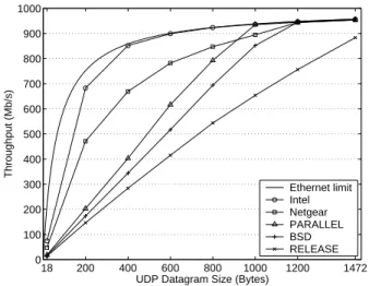
Figure 6 shows the UDP send throughputs achieved by different versions of the Tigon firmware as well as the Intel PRO/1000 MT Server NIC and the Netgear GA622T NIC. The X axis shows UDP datagram sizes varying from 18 bytes (leading to minimum-sized 64-byte Ethernet frames) to 1472 bytes (leading to maximum-sized 1518-byte frames). The Y axis shows throughput in megabits per second of UDP datagrams, excluding network headers. The Ether-net Limit curve represents the theoretical maximum data through-put of the UDP/IP protocol running on Ethernet for a given data-gram size; protocol overheads, including 46 bytes of headers and a trailer per frame, and the required 20 bytes of preamble and inter-frame gap per inter-frame, prevent the full utilization of 1 Gb/s for data. PARALLEL outperforms both BSD and RELEASE across all datagram sizes and delivers up to 32% more throughput than both (with 800-byte datagrams). As the datagram size decreases from the maximum, throughput diverges from the Ethernet limit and starts decreasing linearly starting at 1000-byte datagrams for BSD and RELEASE and 800-byte datagrams for PARALLEL. The packet processing rate in packets per second corresponds to the slope of the throughput curve. The linear decrease indicates that the firmware handles a constant rate of packets regardless of the data-gram size, and that the processors in the Tigon are saturated. The Intel NIC saturates Ethernet with 400-byte or larger datagrams and delivers over 100% more throughput than PARALLEL with smaller datagrams. The Netgear NIC does not saturate Ethernet even with maximum-sized datagrams and performs worse than PARALLEL for datagram sizes 400 bytes or greater.
As discussed in Section 4.2, PARALLEL utilizes both proces-sors to send packets and increases scratch pad efficiency by storing all event handlers in the scratch pads. Figure 7 shows the con-tributions from the parallelization and scratch pads by comparing the base PARALLEL with the SRAM-CODE, SRAM-DATA, and SRAM-BOTH versions, and with the SRAM-BOTH version of RE-LEASE. The throughput difference between RELEASE(SRAM-BOTH) and PARALLEL(SRAM-RELEASE(SRAM-BOTH) shows that the improve-ment due to parallelization alone is at most 13% for this work-load, because only one of the send events (Mailbox) is processed by CPU A. PARALLEL delivers up to 89% more throughput than
18 200 400 600 800 1000 1200 1472 0 100 200 300 400 500 600 700 800 900 1000
UDP Datagram Size (Bytes)
Throughput (Mb/s) Ethernet Limit Intel Netgear PARALLEL BSD RELEASE 18 200 400 600 800 1000 1200 1472 0 100 200 300 400 500 600 700 800 900 1000
UDP Datagram Size (Bytes)
Throughput (Mb/s) PARALLEL PARALLEL(SRAM−DATA) PARALLEL(SRAM−CODE) PARALLEL(SRAM−BOTH) RELEASE(SRAM−BOTH)
Figure 6: UDP send throughputs achieved by the Tigon run-ning various firmware versions and by the Intel PRO/1000 MT Server NIC and the Netgear GA622T NIC with various data-gram sizes.
Figure 7: Differences in UDP send throughputs due to the use of the scratch pads.
18 200 400 600 800 1000 1200 1472 0 100 200 300 400 500 600 700 800 900 1000
UDP Datagram Size (Bytes)
Throughput (Mb/s) Ethernet limit Intel Netgear PARALLEL BSD RELEASE 18 200 400 600 800 1000 1200 1472 0 100 200 300 400 500 600 700 800 900 1000
UDP Datagram Size (Bytes)
Throughput (Mb/s) PARALLEL PARALLEL(SRAM−DATA) PARALLEL(SRAM−CODE) PARALLEL(SRAM−BOTH) RELEASE(SRAM−BOTH)
Figure 8: UDP receive throughputs achieved by the Tigon run-ning various firmware versions and by the Intel PRO/1000 MT Server NIC and the Netgear GA622T NIC with various data-gram sizes.
Figure 9: Differences in UDP receive throughputs due to the use of the scratch pads.
PARALLEL(SRAM-BOTH) with 800-byte datagrams, showing that increased utilization of the scratch pads contributes most to the improvement of the parallelized firmware over the sequential firmware for this workload.
The parallelized firmware also improves UDP receive through-put. Figure 8 shows the UDP receive throughputs achieved by var-ious versions of the firmware, by the Intel PRO/1000 MT Server NIC, and by the Netgear GA622T NIC. PARALLEL achieves up to 19% more throughput than BSD, which in turn consistently outper-forms RELEASE for this workload. As datagram size decreases, the throughput of BSD falls below the Ethernet limit for datagram sizes less than 1200 bytes, indicating that the processor is saturated by packet processing. In contrast, PARALLEL does not fall below the limit until the datagram size falls below 1000 bytes. The UDP
receive throughput of RELEASE never reaches the Ethernet limit. As with UDP send throughputs, the Intel NIC saturates Ethernet with 400-byte or larger datagrams and achieves over 100% more throughput than PARALLEL with smaller datagrams. The UDP receive throughput of the Netgear NIC is far greater than its UDP send throughput. However, it still performs worse than PARAL-LEL for large datagrams of size 1000 bytes or greater.
The improvement of PARALLEL again comes from both par-allelization and increased utilization of the scratch pads. Fig-ure 9 shows throughput increases due to the parallelization and scratch pads. Receive benefits from the parallelization since CPU B handles the Receive Buffer Descriptor Ready and DMA Read Complete events related to informing the NIC about main memory buffers pre-allocated by the device
18 200 400 600 800 1000 1200 1472 0 200 400 600 800 1000 1200 1400 1600 1800 2000
UDP Datagram Size (Bytes)
Throughput (Mb/s) Ethernet limit Intel Netgear PARALLEL BSD RELEASE 18 200 400 600 800 1000 1200 1472 0 200 400 600 800 1000 1200 1400 1600 1800 2000
UDP Datagram Size (Bytes)
Throughput (Mb/s) PARALLEL PARALLEL(SRAM−DATA) PARALLEL(SRAM−CODE) PARALLEL(SRAM−BOTH) RELEASE(SRAM−BOTH)
Figure 10: UDP bidirectional throughputs achieved by the Tigon running various firmware versions and by the Intel PRO/1000 MT Server NIC and the Netgear GA622T NIC with various datagram sizes.
Figure 11: Differences in UDP bidirectional throughputs due to the use of the scratch pads.
driver. PARALLEL(SRAM-BOTH) provides roughly 18% greater throughput than RELEASE(SRAM-BOTH), showing the improve-ment due to the parallelization alone. PARALLEL delivers up to 66% more throughput than PARALLEL(SRAM-BOTH) indicating that most of the improvement of PARALLEL for this workload is again due to the increased utilization of the scratch pads.
The unidirectional UDP workloads suggest that the parallelized firmware benefits primarily from better scratch pad utilization. These workloads benefit little from utilizing both processors be-cause the static event partition only targets load balance for bidirec-tional traffic that equally emphasizes send and receive. Figure 10 shows the bidirectional UDP throughputs achieved by different ver-sions of the firmware, by the Intel PRO/1000 MT Server NIC, and by the Netgear GA622T NIC. The Ethernet limit is now doubled since the network links are full-duplex. Compared to RELEASE, PARALLEL increases throughput by 65% with 1472-byte data-grams and 157% with 18-byte datadata-grams. Compared to BSD, PAR-ALLEL increases throughput by 37% with 1472-byte datagrams and 146% with 18-byte datagrams. For datagram sizes less than 600 bytes, PARALLEL delivers over 100% more throughput than either BSD or RELEASE. The sublinear increase of PARALLEL throughput starting at 600-byte datagram sizes and 1 Gb/s of data throughput indicates that the packet processing rate is starting to decrease for larger datagram sizes. Since the firmware includes no size-dependent overheads, this decrease indicates an increase in contention for hardware resources that incur per-byte overheads (such as the DMA and MAC controllers, the PCI and Ethernet in-terfaces, or the external SRAM) as the Tigon attempts to serve over 1 Gb/s of network data throughput. As expected from the throughputs for unidirectional traffic, the Intel NIC outperforms the Tigon for bidirectional traffic as well. With 1472-byte data-grams, the Intel NIC achieves 1882 Mb/s, close to the Ethernet limit of 1914 Mb/s, whereas PARALLEL achieves 1553 Mb/s. For datagram sizes greater than 400 bytes, PARALLEL performs bet-ter than the Netgear NIC, which achieves a maximum throughput of 1241 Mb/s.
Figure 11 shows that the performance gains of PARALLEL for UDP bidirectional traffic stem from both parallelization and scratch
pads. Parallelization increases throughput by 37–95%, far greater than in the unidirectional workloads. The scratch pads further pro-vide up to 70% increase in throughput.
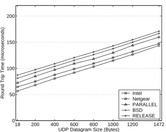
The parallelization improves packet latencies as well as through-puts. Figure 12 shows the UDP ping latencies achieved by various versions of the firmware, by the Intel PRO/1000 MT Server NIC, and by the Netgear GA622T NIC. PARALLEL reduces ping laten-cies by an average of 6% and 10% when compared to RELEASE and BSD, respectively. The Intel NIC again performs best. The Intel and Negear NICs achieve an average of 15% and 9% lower latencies than that of PARALLEL, respectively.
The small ping latency reductions of PARALLEL over RE-LEASE are expected because ping is essentially an alternating uni-directional workload rather than a simultaneous biuni-directional work-load. Specifically, the server first sends a packet to the client. Upon receiving the packet, the client then sends a packet back to the server. Since there is only one packet in transit at any given time, the benefits of the parallelization only come from two sources. First, there is some overlap between the execution of the Mailbox and Send Buffer Descriptor Ready events. CPU B starts executing the Send Buffer Descriptor Ready event before CPU A completes the Mailbox event and reenters the event dispatch loop. Second, the modified Update Send Consumer event in PARALLEL com-pletes quicker than the original unmodified event in RELEASE. The modified event updates only the local copy of the send ring consumer index, whereas the original unmodified event must also enqueue a DMA transfer to update the copy in main memory. Fig-ure 13 shows that the parallelization and increased utilization of the scratch pads contribute almost equally to the reduced latencies of PARALLEL. PARALLEL(SRAM-BOTH) achieves an average of 10% lower latencies than RELEASE(SRAM-BOTH), and PAR-ALLEL in turn achieves an average of 8% lower latencies than PARALLEL(SRAM-BOTH).
6.2
Macrobenchmark Performance
The macrobenchmarks also benefit from the parallelized firmware. Table 3 shows the HTTP content throughput in Mb/s achieved by the thttpd web server and the packet routing
through-18 200 400 600 800 1000 1200 1472 0 50 100 150 200
UDP Datagram Size (Bytes)
Round Trip Time (microseconds) IntelNetgear
PARALLEL BSD RELEASE 18 200 400 600 800 1000 1200 1472 0 50 100 150 200
UDP Datagram Size (Bytes)
Round Trip Time (microseconds) PARALLELPARALLEL(SRAM−DATA)
PARALLEL(SRAM−CODE) PARALLEL(SRAM−BOTH) RELEASE(SRAM−BOTH)
Figure 12: UDP ping latencies achieved by the Tigon running various firmware versions, by the Intel PRO/1000 MT Server NIC, and by the Netgear GA622T NIC with various datagram sizes.
Figure 13: Differences in UDP ping latencies due to the use of the scratch pads.
BSD RELEASE PARALLEL Intel Netgear thttpd (Mb/s) NASA 689 636 944 942 807 Rice 659 616 932 925 775 WC 587 550 702 870 728 Click (K pkt/s) ADV 134 113 150 166 N/A AIX 133 115 173 198 N/A MEM 133 119 247 276 N/A
Table 3: Throughput achieved by the thttpd web server and Click software IP router with the Tigon running various firmware versions, Intel PRO/1000 MT Server NIC, and Netgear GA622T NIC.
put in thousands of packets per second achieved by the Click soft-ware IP router. The Click performance of the Netgear NIC is not available due to an incompatibility between Click and the device driver for the NIC. The PARALLEL firmware increases HTTP con-tent throughput by 20–41% over BSD and by 48–73% over RE-LEASE. The Tigon running PARALLEL performs slightly better than the Intel NIC for the NASA and Rice traces and only 20% worse for WC. The Tigon running PARALLEL achieves over 20% more throughput than the Netgear NIC for the NASA and Rice traces and about 4% less for the WC trace. Similarly, PARALLEL increases packet routing throughput by 12–86% over BSD and by 32–107% over RELEASE. The Click throughput achieved by the Tigon running PARALLEL is only 10–13% lower than that of the Intel NIC. These results indicate that parallelizing the network in-terface firmware enables a programmable NIC to achieve through-put competitive with modern ASIC-based NICs for real network services. Combined with the underlying potential to extend the functionality of network services, parallelization thus makes pro-grammability a viable and attractive option for high-performance network interface design.
7.
DISCUSSION
Embedded processors cannot scale in frequency or complexity as aggressively as general-purpose processors. Consequently, pro-grammable network interfaces must rely on multiprocessor archi-tectures to achieve network link speeds as they scale to 10 Gb/s and
beyond. However, such rapidly growing link speeds will likely re-quire more than just two processors, making it difficult to achieve high performance using only statically-exposed task-level concur-rency.
The static partition of event handlers described in Section 4 ef-fectively balanced the workload across two processors. However, a greater number of processors makes it more difficult to balance load in the same fashion, given that the event handlers have dif-ferent processing requirements. Instead, the firmware may dynam-ically choose the processor to handle a given event. While this may improve load balance, it creates additional overhead by re-quiring mutual exclusion to prevent simultaneous execution of an event handler or simultaneous access to data and resources shared across event handlers that may now run on any processor. Simi-larly, dynamic partitioning also degrades locality for shared vari-ables, private variables that persist across handler invocations, and event handler code, since any processor may access these data or code regions in the future. The specific implications for the Tigon are contention for the single hardware semaphore and less efficient utilization of the scratch pads, likely offsetting the performance benefits of load balancing. However, other architectures may gain greater benefits from dynamic partitioning.
The parallelization scheme discussed in this paper exploits task-level concurrency in which the unit of concurrency is an event han-dler. Thus, the granularity of load balancing is limited by the distri-bution of processing times for the execution of an individual
han-dler, even with dynamic partitioning. For instance, a distribution that is greatly skewed by some event handlers that require signifi-cantly more processing than others leads to a poor balance of load. To mitigate this imbalance, the firmware may parallelize the execu-tion of the most demanding handlers. One approach to reducing the granularity of concurrency in this fashion would be to exploit par-allelism across independent packets, allowing a single handler to process unrelated packets simultaneously on multiple processors. As with dynamic partitioning, parallelization of individual handlers may introduce further synchronization overhead due to sharing of variables and hardware resources.
Static partitioning, dynamic partitioning, and parallelizing par-ticular event handlers all have advantages and disadvantages as discussed above. With more than two processors available, an ef-fective parallelization would benefit from the use of all three ap-proaches, as they complement each other. More advanced hardware can also provide features to address some of the problems caused by each approach to parallelization.
The static partition presented in this paper targets bidirectional traffic with equal emphasis on send and receive in order to measure the impact of parallelization on maximum throughput. This parti-tioning scheme should also benefit most applications since perfor-mance of send and receive both improve. To optimize perforperfor-mance for specific applications, the static partition should use workloads for those applications to profile execution times of event handlers and to derive static partitions. Likewise, future network links may also require different workloads to achieve maximum throughput. Then, those workloads should be used to profile execution times and to derive partitions.
8.
RELATED WORK
Many researchers have used programmable network interfaces to implement user-level protocols directly in network interfaces or to analyze performance issues in network servers [4, 5, 12, 15]. Shivam et al. implemented a parallelized version of their own Eth-ernet Message Passing (EMP) protocol on the Tigon [15]. EMP is a specialized message passing protocol for clusters, designed to provide a low latency and high bandwidth message passing system that is based on user-level access to Gigabit Ethernet [14]. The performance results presented in this paper show that parallelized Ethernet firmware can also improve the throughput of standard IP-based protocols and applications, enabling performance compara-ble to modern ASIC-based network interfaces. The parallelization scheme for EMP statically partitions send and receive processing, somewhat similarly to the partitioning scheme described in Sec-tion 4.2. However, they empirically pick a partiSec-tion of major func-tional components among a few different partitions based on their experimental results, rather than deriving a partition that balances load and minimizes synchronization using profiles as well as care-ful analysis of hardware and data sharing.
Another widely used programmable network interface is the Myricom LANai adapter for Myrinet networks [3]. Gallatin et al. developed the Trapeze/IP firmware for these adapters, implement-ing various techniques to reduce the overhead of sendimplement-ing and re-ceiving packets [5]. By using large messages (much greater than standard Ethernet frames), the authors were able to achieve near-Gigabit rates on relatively slow machines. Buonadonna and Culler developed Queue Pair IP, which replaces the traditional socket ab-straction in order to reduce networking overhead for system area networks [4]. Queue Pair IP uses the existing Internet protocols as its transport layer, and the prototype implements components of TCP/IP directly in the LANai adapter. The authors show that Queue Pair IP can reduce load on CPU while providing lower latency and
higher bandwidth than either Gigabit Ethernet or Myrinet with the traditional socket layer. While these and other similar projects im-prove networking performance for system area networks, the par-allelization scheme for the firmware presented in this paper is inde-pendent of the particular user-level protocols because the basic role of network interfaces is still sending and receiving packets.
Others have studied increasing networking performance by par-allelizing network protocols on general-purpose multiprocessor op-erating systems [2, 6, 10]. Such parallelization schemes exploit concurrency at various levels, such as across packets, protocol lay-ers, and connections. Parallel network protocol processing deals with the layers above the network interface, and can thus improve performance in conjunction with the network interface layer paral-lelization scheme described here.
9.
CONCLUSIONS
Programmable network interfaces provide the potential to extend the functionality of network services, but their instruction process-ing overheads are a performance disadvantage over application-specific network interfaces. However, this performance disadvan-tage can be offset by exploiting task-level concurrency in network interface processing. This paper proposes and analyzes a paral-lelization strategy to target bidirectional IP traffic using the two pro-cessors of the Tigon network interface controller, a chip released in 1997. By carefully partitioning the handler procedures that process various events related to the progress of a packet, the system can achieve load balance while exploiting locality in the on-chip mem-ories with minimal sharing and no synchronization. Such paral-lelization increases throughput by 65% for bidirectional UDP traf-fic of maximum-sized packets, 157% for bidirectional UDP traftraf-fic of minimum-sized packets, and 32–107% for real network services. This parallelization enables performance within 10–20% of a mod-ern ASIC-based network interface for real network services.
Future Ethernet speeds are expected to continue growing; ex-perimental controllers already implement the 10 Gigabit Ethernet specification. Although clock speeds of programmable network in-terface controllers will grow above the 88 MHz rate of the Tigon, the clock rate is unlikely to grow at the same unrestricted pace as general-purpose CPUs because of the limited power and cooling area available to any peripheral device. This frequency constraint eliminates the possibility of uniprocessor programmable NICs sup-porting future Ethernet wire speeds, making further study of con-currency in network interface processing essential for providing high-performance extended network services.
10.
REFERENCES
[1] Alteon WebSystems. Gigabit Ethernet/PCI Network
Interface Card: Host/NIC Software Interface Definition, July
1999. Revision 12.4.13.
[2] M. Bj¨orkman and P. Gunningberg. Locking effects in multiprocessor implementations of protocols. In Proceedings
of the ACM SIGCOMM ’93 Conference, pages 74–83. ACM
Press, 1993.
[3] N. J. Boden, D. Cohen, R. E. Felderman, A. E. Kulawik, C. L. Seitz, J. N. Seizovic, and W.-K. Su. Myrinet: A Gigabit-per-Second Local Area Network. IEEE MICRO, 15(1):29–36, 1995.
[4] P. Buonadonna and D. Culler. Queue Pair IP: A Hybrid Architecture for System Area Networks. In Proceedings of
the 29th International Symposium on Computer Architecture,
[5] A. Gallatin, J. Chase, and K. Yocum. Trapeze/IP: TCP/IP at Near-Gigabit Speeds. In Proceedings of the FREENIX Track:
1999 USENIX Annual Technical Conference, June 1999.
[6] N. C. Hutchinson and L. L. Peterson. The x-Kernel: An Architecture for Implementing Network Protocols. IEEE
Transactions on Software Engineering, 17(1):64–76, Jan.
1991.
[7] H. Kim, V. S. Pai, and S. Rixner. Improving Web Server Throughput with Network Interface Data Caching. In
Proceedings of the Tenth International Conference on Architectural Support for Programming Languages and Operating Systems, pages 239–250, October 2002.
[8] R. Morris, E. Kohler, J. Jannotti, and M. F. Kaashoek. The click modular router. ACM SIGOPS Operating Systems
Review, 34(2):24–25, 2000.
[9] T. Mudge. Power: A First-Class Architectural Design Constraint. Computer, 34(4):52–58, April 2001.
[10] E. M. Nahum, D. J. Yates, J. F. Kurose, and D. F. Towsley. Performance Issues in Parallelized Network Protocols. In
Proceedings of the Operating Systems Design and Implementation, pages 125–137, 1994.
[11] J. Poskanzer. thttpd - tiny/turbo/throttling HTTP server. Acme Labs, Feb. 2000. Unix manual page.
[12] I. Pratt and K. Fraser. Arsenic: A User-Accessible Gigabit Ethernet Interface. In Proceedings of IEEE INFOCOM ’01, pages 67–76, 2001.
[13] J. Satran, K. Meth, C. Sapuntzakis, M. Chadalapaka, and E. Zeidner. iSCSI. IETF Internet draft
draft-ietf-ips-iscsi-14.txt, work in progress, July 2002.
[14] P. Shivam, P. Wyckoff, and D. Panda. EMP: Zero-copy OS-bypass NIC-driven Gigabit Ethernet Message Passing. In
Proceedings of the 2001 ACM/IEEE Conference on Supercomputing (SC2001), Nov. 2001.
[15] P. Shivam, P. Wyckoff, and D. Panda. Can User-Level Protocols Take Advantage of Multi-CPU NICs? In
Proceedings of the International Parallel and Distributed Processing Symposium (IPDPS’02), pages 64–69, Apr. 2002.