A Mechatronic System for Achieving Optimum
Alignment of Lower Limb Prosthesis
by
Kian Sek TEE
Submitted in accordance with the requirements for the degree of Doctor of Philosophy
The University of Leeds School of Mechanical Engineering
November 2011
The candidate confirms that the work submitted is his own and that appropriate credit has been given where reference has been made to the work of others.
This copy has been supplied on the understanding that it is copyright material and that no quotation from the thesis may be published
ii
_____________________________________________________________________________________________________
Abstract
Misalignment in the lower limb prosthesis can cause great discomfort in the stump-socket interface and disturbance to gait function. In the long run, it could deteriorate the musculoskeletal system. In practice, the assessment still depends heavily on the verbal feedback of an amputee and experiences of a prosthetist. Moreover it is inconsistent amongst the prosthetists.
Prosthetic alignment involves the adjustment of the prosthetic components relative to the gait quality. Some methods were proposed, including symmetry index, variation in a step-to-step transition, stability within the zone of integrated balance, matching roll-over shape (ROS) to an ideal ROS and etc. It is not clear if the optimum alignment could be achieved. These methods exhibit a few limitations, i.e. limited use of gait variables in a single comparison and non-uniform results when different gait variables are applied. There is a need to provide an objective assessment method that processes high dimensional gait variables and presents them in a simple form. In addition, it could be impractical and expensive clinically to spend excessive time on a patient. An ambulatory gait measurement system could achieve this objective to a certain extent.
This research investigates a potential engineering solution that is able to provide an assistive and objective assessment of the lower limb prosthetic alignment that provides optimal gait quality.
iv
_____________________________________________________________________________________________________
Content
Abstract ...ii
Acknowledgement ... iii
Content ...iv
List of Abbreviations... viii
List of Figures ...xi
List of Tables...xiv
Chapter 1 Introduction...1
1.1 Background ...1
1.2 Motivation...3
1.3 Aims and Objectives ...4
1.3.1 Aims ...4
1.3.2 Objectives...5
1.4 The Scope of this Research ...5
1.5 Contributions of this research ...5
1.6 Organization of the Thesis ...7
Chapter 2 Literature Review ...9
2.1 Introduction ...9
2.2 Basic Concepts ...10
2.2.1 Definition of Walking ...10
2.2.2 Anatomical Geometry ...10
2.2.3 Motions of Lower Limbs ...11
2.2.4 Kinematic and Kinetic Parameters...13
2.2.4.1 Step, Stride, Cadence, Velocity...13
2.2.4.2 Angular Properties ...14
v
_____________________________________________________________________________________________________
2.2.6 Roll Over Shape ...18
2.3 Gait Measurement Instruments ...20
2.4 Human Walking Models ...24
2.4.1 The Six Determinants...24
2.4.2 Inverted Pendulum ...24
2.4.2.1 Dynamic Walking ...24
2.4.2.2 Rocker Based Inverted Pendulum...25
2.5 Lower Limb Prosthetic Alignments ...26
2.5.1 The Need for Proper Alignments ...26
2.5.2 Methods of Alignments...28
2.5.3 Arguments of Alignments ...29
2.5.4 Common Alignment Values...33
2.6 Summary ...33
Chapter 3 An Ambulatory System ...35
3.1 Introduction ...35
3.2 Background ...35
3.3 Aims and Objectives ...40
3.4 Datalogger ...41
3.4.1 Circuitry, PCB and others ...41
3.4.2 Assembly of the Datalogger...43
3.4.3 The Program...45
3.4.4 Calibration of the A/D Input Channels ...46
3.5 Inertial Measurement Unit ...47
3.6 The Ambulatory System ...49
3.6.1 The Body Landmarks and Their Axes Assignments...50
3.6.2 Preliminary Trials...51
3.7 Summary ...55
Chapter 4 Static and Dynamic Calibration of an IMU ...56
4.1 Introduction ...56
4.2 Inertial Measurement Unit ...57
4.2.1 Accelerometer ...57
vi
_____________________________________________________________________________________________________
4.2.3 The IMU Used in the Research...60
4.3 Static Calibration...62
4.3.1 Method 1: Conventional Rotary Table...62
4.3.1.1 Experiments...64
4.3.1.2 Results ...65
4.3.2 Method 2: 6/12 Known Positions...74
4.3.2.1 Experiments...76
4.3.2.2 Results ...79
4.3.3 Method 3: In-Use Calibration ...83
4.3.3.1 Experiments...87
4.3.3.2 Results ...87
4.3.4 Comparison of Methods...90
4.4 Dynamic Calibration ...92
4.4.1 Experiments...95
4.4.2 Results ...97
4.4.3 Discussion ...105
4.5 Summary ...105
Chapter 5 Human Gait Trials...107
5.1 Introduction ...107
5.2 Overview of Human Gait Trials...107
5.3 Aims and Objectives ...109
5.4 Equipment ...109
5.4.1 The Body Landmarks...110
5.5 Experiment Design...112
5.5.1 Test-retest Reliability...114
5.5.2 Procedures ...114
5.6 Data Analysis ...116
5.7 Results ...122
5.8 Discussion ...131
5.9 Summary ...132
Chapter 6 A Visual Aid and A Decision Guide ...134
vii
_____________________________________________________________________________________________________
6.2 Aims and Objectives ...135
6.3 Principle Component Analysis...135
6.4 Self Organizing Feature Map ...136
6.5 Methodology ...137
6.6 Results ...139
6.7 Discussion ...148
6.8 Summary ...151
Chapter 7 Summary and Conclusions ...152
7.1 Assessment of the Research Objectives...152
7.2 Conclusions ...154
7.3 Future Works...156
REFERENCES ...157
APPENDIX A Datalogger ...163
APPENDIX B MDED C Program for the Datalogger ...168
APPENDIX C Documentation for Human Gait Trials ...174
viii
_____________________________________________________________________________________________________
List of Abbreviations
2D 2 Dimension
3D 3 Dimension
A/D Analog to Digital
AK Above Knee
AP Anterior Posterior
ASYM Asymmetry
BCOM Body Centre of Mass
BK Below Knee
BMB Bisector of Medial Brim
BMU Best Matching Unit
CA Cronbach's Alpha
CAD Computer Aided Design
CW Clockwise
CCW Counter Clockwise
COM Centre of Mass
COP Centre of Pressure
CSV Comma-Separated Values
D/A Digital to Analog
dof Degree of Freedom
FO Foot Off
FS Foot Strike
FSR Force Sensitive Resistor
GC Gait Cycle
GCI Gait Cycle Index
GRF Ground Reaction Force
vGRF Vertical Ground Reaction Force
HC Heel Contact
HPF High Pass Filter
HS Heel Strike
ix
_____________________________________________________________________________________________________
IMU Inertial Measurement Unit
ISw Initial Swing
L.A.S.A.R. Laser Assisted Static Alignment Reference LiNo GC Linear Interpolated Normalized Gait Cycle
LPF Low Pass Filter
LR Load Response
KAF Knee, Ankle and Foot
MEMS Micro-Electro-Mechanical Systems
MISO Master In Slave Out
ML Medial Lateral
MOSI Master Out Slave In
MSt Mid Stance
MSw Mid Swing
PC Principle Component
PCA Principle Component Analysis
PCB Printed Circuit Board
PSw Pre-Swing
RHR Right Hand Rule
RMS Root Mean Square
ROS Roll Over Shape
RSD Relative Standard Deviation
SCLK Serial Clock
RVCG Rotational Vibratory Coriolis Gyroscope
s Standard Deviation
SD Secure Digital
SE Standard Error
SOFM Self-Organizing Feature Map SPI Serial Peripheral Interface
SS Slave Select
TF Transfemoral
TO Toe Off
TSA Total Sway Activity
TSt Terminal Stance
x
_____________________________________________________________________________________________________
TT Transtibial
WBI Weight-bearing Imbalance
xi
_____________________________________________________________________________________________________
List of Figures
Figure 2.1: Human geometry. Redrawn from [21] ...11
Figure 2.2: Lower limbs motions [21] ...12
Figure 2.3: Ankle and foot motions. Modified from [21] ...12
Figure 2.4: Definition of step and stride. Redraw from [20] ...13
Figure 2.5: Definitions of the limb segment angles. Redrawn from [28] ...14
Figure 2.6: Definition of stance and swing phases. Modified from [20] ...16
Figure 2.7: Double Limb Stance and Single Limb Stance. Redraw from [20]...17
Figure 2.8: Principle of Roll-Over Shape [41]...19
Figure 2.9: Analogy of Roll-Over Shape in a KAF system [41] ...19
Figure 2.10: Rocker Based Inverted Pendulum [38]...26
Figure 2.11: Minimizing lumbar lordosis in bilateral amputees [61] ...28
Figure 2.12: Constraint of acceptable alignments [16] ...31
Figure 2.13: Alignments by matching to an “ideal” ROS [15]...32
Figure 3.1: Main board circuitry ...42
Figure 3.2: Sub-board circuitry...42
Figure 3.3: PCB board drawing of (a) main board (b) sub-board...43
Figure 3.5: The peripheral ports and socket numbers ...44
Figure 3.4: The datalogger ...44
Figure 3.6: Mbed microcontroller programming logic flow...46
Figure 3.7: LCD display message ...46
Figure 3.8: Calibration of 32 analog input channels ...47
Figure 3.9: IMU. (a) Type 1 - ADXL330/IDG300 (b) Type 2 - ADXL335/IDG500 ...48
Figure 3.10: The fixture and strap of an IMU...48
Figure 3.11: The ambulatory system...49
Figure 3.12: IMU. (a) Original Axes (b) Body Axes...51
Figure 3.13: Preliminary results of BCOM...52
Figure 3.14: Preliminary results of (a) left thigh (b) right thigh ...53
Figure 3.15: Preliminary results of (a) left shank (b) right shank...54
xii
_____________________________________________________________________________________________________
Figure 4.2: The principle of Coriolis Acceleration. Redrawn from [85] ...59
Figure 4.3: IMU-5DOF (a) Type-1 (b) Type-2...61
Figure 4.4: Static calibration in a vertical plane. Redrawn from [91]...62
Figure 4.5: Setup of the rotary table method...64
Figure 4.6: The starting position in (a) XY plane (b) YZ plane (c) ZX plane ...65
Figure 4.7: IMU6. Unnormalized outputs of a triaxial accelerometer in (a) XY plane, (b) YZ plane, (c) ZX plane ...67
Figure 4.8: IMU6. Normalized static outputs in (a) XY plane (b) YZ plane (c) ZX plane ...69
Figure 4.9: IMU6. Inter-axis misalignments during 0g ...70
Figure 4.10: IMU6. Gyroscope static outputs at (a) XY plane, (b) YZ plane, (c) ZX plane ...72
Figure 4.11: Inter-axis misalignments. Redrawn from [93, 94]...74
Figure 4.12: Setup of the twelve-known positions method...77
Figure 4.13: Twelve-known positions in the platform coordinate. Redrawn from [96] ...77
Figure 4.14: IMU6. Static outputs at the twelve-known positions ...79
Figure 4.15: Setup of the in-use calibration ...87
Figure 4.16: IMU6. Quasi-static positions detection ...88
Figure 4.17: Free body diagram of an IMU-5DOF in a pendulous system ...94
Figure 4.18: Setup of the dynamic calibration ...95
Figure 4.19: Circuitry of an electronic protractor ...96
Figure 4.20: Calibration of the potentiometer...97
Figure 4.21: Gyroscope output-YR for IMU1 to IMU6 ...98
Figure 4.22: ZPLP pendulous angular velocities for IMU1 to IMU6...99
Figure 4.23: Scale factors of gyroscope output-YR for IMU1 to IMU6 ...100
Figure 4.24: Frequency distribution of the scale factors of the gyro-outputs (YR) for IMU1 to IMU6 ...100
Figure 4.25: The comparison of the calibrated gyro-outputs (YR) with the reference angular velocity...102
Figure 4.26: IMU6. Comparison between the models and the actual outputs in the ZX plane...104
Figure 5.1: Overview of the human gait trials ...108
xiii
_____________________________________________________________________________________________________
Figure 5.3: The body landmarks and the IMUs ...110
Figure 5.4: IMU-5DOF and their axes at the body landmarks ...111
Figure 5.5: Conversion to Body Axes...112
Figure 5.6: Experiment setup modes, S1 to S4 ...114
Figure 5.7: The experimental procedure ...115
Figure 5.8: Gait event identification using the shank lateral gyro-output...120
Figure 5.9: A new gait identification strategy...120
Figure 5.10: GC data structure format ...121
Figure 5.11: Participant 1. BCOM outputs during normal level walking...124
Figure 5.12: Participant 1. Thigh outputs during normal level walking ...125
Figure 5.13: Participant 1. Shank outputs during normal level walking...126
Figure 5.14: Spectral analysis of the IMU outputs at the right shank...127
Figure 5.15: ZPLP right shank outputs ...127
Figure 5.16: Gait identification using the gyro-output (XR) at the right shank...128
Figure 5.17: Participant 1. GCs of the right shank outputs in Week-1 and Week-2 during normal level walking ...129
Figure 6.1: Self-Organizing Feature Map. Redrawn from [104] ...136
Figure 6.2: Selected features within a gait cycle...138
Figure 6.3: Participant 1 at week 1. GC stacks during normal level walking (S1). (a) left shank, (b) right shank...140
Figure 6.4: Variance explained by each principle component (Intrapersonal) ...141
Figure 6.5: Intra-personal view. 2D PCA plots of all participants in week 1 (a, b, c) and week 2 (d, e, f) respectively. ...142
Figure 6.6: Variance explained by principle components (Interpersonal)...143
Figure 6.7: Inter-personal view. 3D PCA plots of each mode in week 1 ...144
Figure 6.8: Inter-personal view. A 2D PCA plot of all modes in week 1...144
Figure 6.9: (a) Trained SOFM with 102 sets of standardized variables as the inputs. (b) Trained SOFM with 102 sets of uncorrelated PCs as the inputs...145
Figure 6.10: Trained SOFM using (a) 102 PCA inputs, (b) PCA inputs nearly 80% of total variance explained ...146
Figure 6.11: SOFM hit counts per neuron ...147
Figure 6.12: SOFM neighbour weight distances amongst adjacent neurons ...147
xiv
_____________________________________________________________________________________________________
List of Tables
Table 2.1: Lower limbs motions and agonist-antagonist muscles. Quoted from [22]
...12
Table 2.2: Task durations in percentages of gait cycle. Redrawn from [20] ...17
Table 2.3: Gait events, periods and phases in %GC [35]...18
Table 2.4: Instruments for gait analysis. Compiled from [20-22, 25, 26]...20
Table 2.5: Reviews of the instruments for gait analysis ...23
Table 2.6: Key parameters for lower limb alignments [1] ...30
Table 3.1: Literature reviews of accelemetric and gyroscopic devices ...36
Table 3.2: IO assignments for the datalogger and IMUs ...44
Table 3.3: IMU allocation at the predefined body landmarks ...50
Table 3.4: Rules for the conversion from the IMU axes to the body axes...50
Table 4.1: Types of IMU-5DOF used in this application ...61
Table 4.2: Key specifications of the IMUs from the manufacturers...61
Table 4.3: Quantity of IMUs and their tag names...62
Table 4.4: IMU6. Calibrated results in three planes ...66
Table 4.5: IMU6. Statistical results of the zero biases and the scale factors ...68
Table 4.6: IMU6. RMS errors between the normalized static outputs and the models ...70
Table 4.7: IMU6. Inter-axis misalignment errors during 0g...70
Table 4.8: IMU6. Zero biases for the gyroscope ...72
Table 4.9: Calibrated results of the accelerometers (IMU1 ~ IMU6)...73
Table 4.10: Calibrated zero biases of the gyroscopes (IMU1 ~ IMU6)...73
Table 4.11: G-values at the twelve-known positions ...78
Table 4.12: Combination for all possible solutions in Set1 and Set2 ...80
Table 4.13: IMU6. The results using the twelve-known positions ...81
Table 4.14: Solution checks for the twelve-known positions ...81
Table 4.15: IMU6. The results using the six-known positions ...82
Table 4.16: Solution checks for the six-known positions ...82
Table 4.17: Comparison of twelve-known and six-known positions...83
xv
_____________________________________________________________________________________________________
Table 4.19: IMU6. The results using optimization command(fmincon)...89
Table 4.20: Lowest cost function’s value for IMU1 to IMU6 ...89
Table 4.21: The results using the in-use calibration ...90
Table 4.22: Comparison of static calibration techniques ...91
Table 4.23: Calibrated scale factors of the gyroscopes...101
Table 4.24: Calibrated average zero biases of the gyroscopes...101
Table 4.25: RMS between the gyroscope and the reference (Pot)...103
Table 4.26: Geometry offsets of an IMU in a pendulous system...103
Table 4.27: RMS between the models and the actual outputs for IMU1 to IMU6 .104 Table 5.1: The body landmarks and the IMUs...110
Table 5.2: Protocol for the conversion from the IMU axes to the body axes ...112
Table 5.3: Experiment setup modes ...113
Table 5.4: Review of the cut-off frequency ...117
Table 5.5: Review of gait identification methods ...119
Table 5.6: Bio data of the participants ...122
Table 5.7: Participant 1. Cronbach’s Alpha of the right shank outputs during normal level walking ...130
CHAPTER 1
INTRODUCTION
1.1
Background
Misalignment in lower limb prostheses could cause serious skin issues and damages to the musculoskeletal system if not corrected. Undesired pressure distribution in the stump/socket interface [1-7] would result in great discomfort, and continuous mechanical abrasion will eventually cause tissue breakdown, bruise, irritation, stump pain and skin problems. Stump skin damages are serious and should be avoided. Furthermore, heavy and consistent dependency on the sound limb would cause undesired pressure distribution to the rest of musculoskeletal system [8] and hence increase in the prevalence of degenerative changes in the lumbar spines and knee.
Chapter 1: Introduction 2
_____________________________________________________________________________________________________
prosthesis. Later, Sin [16] re-examined the accepted range and found that a non-level walking test could constraint the acceptable range into a smaller set.
Instrumental gait analysis is crucial for providing a scientific view of walking performance with reported error margins. These instruments provide measurements in temporal, kinematic or kinetic properties of the gait. A gait analysis laboratory may consist of commercial gait measurement instruments such as a vision motion capture system to acquire temporal and kinematic gait data, while using a force plate to measure the ground reaction force within a step. Examples of a vision motion capture system and a force plate are Vicon and Kistler respectively. The commercial motion capture systems provide reliable measurement consistency and accuracy which are reported in their datasheets. In practice, they are expensive and stationary in a confined room.
On the other hand, an ambulatory gait measurement system provides a choice for portable and continuous gait measurements outside a gait laboratory. A number of sensory units that feature light-weight and small in size could be used for direct measurements. A Micro-Electro-Mechanical System (MEMS) type Inertial Measurement Unit (IMU) is light-weight and small in size, relatively cheap, reliable and accurate. An IMU could measure kinematic properties of the limb segments in multiple axes. Commercial MEMS IMUs from Xsens, MEMSense, MicroStrain, MotionNode etc. for example, give a broad range of selections such as types and number of transducers (accelerometer, gyroscope and magnetometer) incorporated, number of degree of freedom (dof) per transducer, signal choices (USB, SPI, I2C, RS232 or analogue voltage) as well as the calibration and analytical software. Off-the-shelf IMUs for gait measurement are rather expensive as compared to their electronic components. An example of MEMS IMU is the integration of ADXL335 (3-axis accelerometer, Analog Devices, Inc.) and IDG500 (2-axis gyroscope, InvenSence, Inc.). However, skilled circuitry development to assemble these ICs is required. The IMU needs to be calibrated before applying it for motion data acquisition.
Chapter 1: Introduction 3
_____________________________________________________________________________________________________
gait parameters are suggested to be weighted via these algorithms since these algorithms are mathematically incapable to handle high dimensional data at once. Nowadays, gait data are easily available in high dimensions. It may be an irrational sense just to limit to a number of choices. Since walking is a series of voluntary controlled motions, the gait data should map to a distribution with a centre tendency. The gait data are postulated to form the gait patterns as the results of alignments and other restrictions. Next, the challenge would be to present the multi-dimensional data in a simple form that displays the centre tendency. In practice, a prosthetist spends limited time in monitoring the patient’s gait. Short gait monitoring time might possibly result in insufficient observation as the patient leaves the clinic. It is envisaged that an ambulatory system instead of a stationary system would provide a longer observation and collect sufficient gait data.
1.2
Motivation
Some methods were proposed, including symmetry index [5, 9, 16, 17], variation in a step-to-step transition [10, 18], stability within zone of integrated balance [11] and matching roll-ever shape (ROS) to an ideal ROS [14, 15] (see arguments of these methods in Chapter 2). These reported methods for lower limb prosthetic alignment assessment still exhibit a few limitations as listed.
1. The first limitation is the limited use of gait variables in a single comparison. For example, a symmetry index would compare the stride speed of the left leg and the right leg. In another example, variations of thigh moments in a step-to-step transition are calculated and plotted to justify the quality of an alignment.
Chapter 1: Introduction 4
_____________________________________________________________________________________________________
3. The third limitation is inadequate observation time during an alignment session. From the prescription point of view, it could be impractical and costly in clinical practices to spend excessive time on a patient. Gait observation during a schedule gait trial could be insufficient to provide adequate gait data for analysis. The amputee would adapt to a new gait pattern over the long run upon any alignment updates. An ambulatory gait measurement system which could continuously collect sufficient amount of gait data out of the clinic could achieve this objective to a certain extent.
It is arguable that the lower limb prosthetic assignment and its assessment must be limited to a pre-scheduled clinical session and must be confined within a certain types of gait variables and must investigate the sensitivity of certain gait variables with regard to the alignment. To date, a typical instrumental gait measurement would easily generate many gait variables. Simple plots and statistical analysis focused on a limited number of gait variables may be insufficient to reveal the ‘true’ gait quality. It could be a waste of information by discarding part of the gait variables without proper justification. Since human walking involves a high synchronization of falling and supporting of the body controlled by the lower limbs, repeated gait variables measured from predefined body segments could possibly reveal crucial gait patterns due to the alignment. There is a need to provide an objective assessment method for the application of lower limb prosthetic alignment, that acquires sufficient amount of gait data and processes high dimensional gait variables and presents them in a simple form.
1.3
Aims and Objectives
1.3.1 Aims
1. To design a low cost portable mechatronic system that is able to monitor gait in lower limb segments during normal walking.
Chapter 1: Introduction 5
_____________________________________________________________________________________________________
1.3.2 Objectives
1. To develop an ambulatory system for gait data collection. The system should be portable and low cost.
2. To calibrate the ambulatory system including the datalogger and the sensors. The efforts should specify the system and provide margin of errors.
3. To collect gait data using the ambulatory system under several walking restrictions.
4. To propose a procedure of gait data processing. The procedure involves multi-stages of signal processing and conditioning.
5. To propose a simple presentation of gait data that could provide essential visual aids and guides during lower limb prosthetic alignments.
1.4
The Scope of this Research
The project could cover many stages of research and development phases before reaching a clinically proven solution. However, at this early stage, this project is intended to provide a potential solution to the problem and is limited into these scopes.
1. To develop a low-cost ambulatory gait measurement system that could be used indoors and outdoors.
2. To propose a novel assessment method that consider a compound set of gait variables
3. To use healthy subjects to validate the proposed solution
1.5
Contributions of this research
As a contribution to the body of knowledge, part of the thesis are published in peer-reviewed conferences. The development of the ambulatory system as reported in Chapter 3 is published in The 2011 International Conference of Mechanical Engineering, July 6-8, London, UK, 2011. Different techniques of static calibration of an triaxial accelerometer and the comparison of these techniques as reported in Chapter 4 are published in:
Chapter 1: Introduction 6
_____________________________________________________________________________________________________
The 2011 International Conference of Mechanical Engineering, July 6-8, London, UK, 2011.
From the same chapter, the dynamic calibration of a gyroscope using a simple pendulous rig and a statistical method is published in The 14th International Conference on Climbing and Walking Robots and the Support Technologies for Mobile Machines (CLAWAR2011), September 6-8, Paris, France, 2011. Further works and findings from the research will be published in peer-reviewed journals. The citations of the publications are listed in Appendix D.
Further contributions of this research work can be summarized as:
1. Proposing the development consideration of an ambulatory system. This includes the embedded system design and the recommendation of IMU sensory axes conversion according to the body axes at predefined body landmarks. 2. Revising and comparing several IMU static calibration methods. The
comparison reveals the advantages and disadvantages of each method. An innovative procedure using 6/12 known positions and the iterative mathematical solution proves to be useful and easy to apply.
3. Proposing an innovative dynamic calibration for a gyroscope using a pendulous system.
4. Proposing a validation method for IMU dynamic performance using a pendulous system. The IMU actual outputs are compared with the theoretical models formulated from the principle of circular motions.
5. Proposing a novel set of cross-designed experiments to investigate the effect of a crucial alignment factor (ankles) and the walking level to the gait quality. 6. Proposing an innovative procedure to systematically process the collected gait
data into a structure of normalized and linear interpolated gait cycles.
Chapter 1: Introduction 7
_____________________________________________________________________________________________________
1.6
Organization of the Thesis
The thesis is divided into seven chapters. Chapter 2 reviews the problem background of the research. A general knowledge on human waking and biomechanics is reviewed. This includes essential definitions regarding walking and crucial concepts for gait analysis. The review also investigates specially on the issues regarding lower limb prosthetic alignments. These issues include the importance and the need for the alignments, reviews on many alignment methodologies, tools and their arguments. Lastly, contribution of this research to the body of knowledge are mentioned.
Chapter 3 presents the design and development of an ambulatory system which consists of a customized embedded datalogger, five units of inertial measurement units (IMUs) and straps to hold the devices.
Chapter 4 describes the procedures for both static calibration and dynamic calibration of an IMU. The accelerometers are calibrated using several static calibration techniques and these techniques are compared. A pendulous system is recommended for the dynamic calibration. A frequency distribution method is proposed to calibrate the gyroscope. Finally dynamic performances of an IMU are verified by comparing its theoretical models and the actual measurements in the pendulous system.
Chapter 5 reports the procedures of human walking trials and their results. The experiments are cross-designed using two walking restriction factors that influence the gait. The factors are the ankle and the walking level. The experiments received an ethical approval from the Research Support Unit of the University of Leeds and consents from the participants. The procedure for gait feature extraction is demonstrated. It includes multi-stages of signal processing and conditioning techniques, gait events identification, gait features selection and extraction out of processed gait data. The reliability of the ambulatory system (see Chapter 3) is justified using a statistical method called test-retest reliability.
Chapter 1: Introduction 8
_____________________________________________________________________________________________________
patterns in low dimensional plots. By means of a 2D or 3D plot, both PCA and trained SOFM are able to show clear clusters of gait performances under different walking restrictions. A trained SOFM could determine the class of a gait pattern in future applications.
CHAPTER 2
LITERATURE REVIEW
2.1
Introduction
This chapter reviews the background knowledge regarding the study of human locomotion and lower limb prosthetic alignments. In a broader view, the review would give a general understanding about the studies of human locomotion and their relevant discoveries. In specific, the review would provide a deeper understanding regarding the researches in the lower limb prosthetic alignments and their relevant discoveries. Lastly, the contributions of this research to the body of knowledge are mentioned.
The review starts with fundamental concepts and terminologies in the study of human locomotion. They include formal definitions of walking, anatomical geometry, motions in lower limbs in kinematic and kinetic terms. These definitions form the background knowledge necessary for gait analysis. All studies in human locomotion cannot leave without gait data collection with reliable gait measurement instruments. A review of these instruments and their limitations are provided.
Next, a few human walking models are reported. Each model emphasizes on different key variants that determine gait quality. The classical human walking model, the six determinants, has gone through several challenges and is seriously questioned. However, it still describes well about human walking. The model, dynamic walking, utilizes the law of conservation of energy to model the walking actions. Meanwhile, the model, rocker based inverted pendulum, utilizes the geometry of roll-over shape (ROS) to anticipate the virtual leg length. Optimal values of ROS radius and virtual leg length are suggested.
Chapter 2: Literature Review 10
_____________________________________________________________________________________________________
methodologies and their arguments regarding the lower limb prosthetic alignments are reviewed.
2.2
Basic Concepts
2.2.1 Definition of Walking
Inman [19] defines locomotion as a rhythmic displacement of body parts in forward progression, either walking or running. Different to walking, the period of double limb support during running disappears and both limbs are at not on the ground for a brief period. Perry [20] describes walking as a repetitious pattern of reciprocal floor contact by lower limbs to move the body forward in a stable manner. Above all, Whittle [21] provides specific tasks of walking as quoted “…accomplish four things:
1. Each leg in turn must be able to support the body weight without collapsing. 2. Balance must be maintained, either statically or dynamically, during single
leg stance.
3. The swinging leg must be able to advance to a position where it can take over the supporting role.
4. Sufficient power must be provided to make the necessary limb movements and to advance the trunk. “
2.2.2 Anatomical Geometry
Chapter 2: Literature Review 11
_____________________________________________________________________________________________________
[image:25.595.168.498.145.390.2]from the centre of body. Proximal means towards the centre of the body. Detail human anatomical descriptions could be found in most kinesiology textbooks.
Figure 2.1: Human geometry. Redrawn from [21]
2.2.3 Motions of Lower Limbs
Voluntary lower limb motions are mostly joint-segment rotations and are specifically named as shown in Figure 2.2. The paired motions are the resultant contraction of the agonist-antagonist muscles. In the frontal plane view, abduction is the movement away from the medial while adduction does the opposite. In the sagittal plane view, the hip flexion is the raise of thigh toward the body while the hip extension does the opposite. The knee extension is the movement to extend or straighten the shank while knee flexion defines the action of knee bending. A few crucial foot motions are recognized. For ankle and foot as shown in Figure 2.3, in the sagittal plane, dorsiflexion describes the revolute action of the foot pivoted at the ankle that bends the foot toward the shank while plantarflexion does the opposite. Eversion is the rotation of the foot about the ankle that the sole turns away from the median plane while inversion does the opposite. Foot abduction and adduction could be observed as the complex joint-segment rotations that rotate the insole away and toward the median plane respectively. Furthermore, Kirtley [22]
Superior
Inferior Posterior
Anterior Left
Right
Chapter 2: Literature Review 12
_____________________________________________________________________________________________________
provides a better understanding by relating corresponding key agonist-antagonist muscles for each pair of motions, as shown in Table 2.1.
[image:26.595.136.479.113.521.2]Figure 2.2: Lower limbs motions [21]
[image:26.595.111.532.570.750.2]Figure 2.3: Ankle and foot motions. Modified from [21]
Table 2.1: Lower limbs motions and agonist-antagonist muscles. Quoted from [22]
Joint Motion Key muscles Hip Flexion/Adduction/Medial rotation Iliopsoas
Extension/Abduction/Lateral rotation Gluteus maximus, medius Knee Extension Quadriceps
Flexion Hamstrings Ankle/Foot Dorsiflexion Tibialis anterior
Plantarflexion Gastrocnemius, soleus Inversion Tibialis posterior Eversion Peroneal
Sagittal Plane Dorsiflexion
Plantarflexion
Ankle Left leg Right leg
Frontal \Plane
Eversion Inversion
Rear View Sagittal plane Adduction
Abduction
Adduction Abduction
Frontal plane
Extension Flexion
Chapter 2: Literature Review 13
_____________________________________________________________________________________________________
2.2.4 Kinematic and Kinetic Parameters
Kinematic and kinetic parameters are normally applied during gait analysis. These parameters are well-explained in literatures [23, 24] and textbooks [20-22, 25, 26] relating to human biomechanics or gait analysis. A few key concepts and terminologies are elaborated below. More detail could be found in most textbooks regarding kinesiology and human biomechanics.
2.2.4.1 Step, Stride, Cadence, Velocity
[image:27.595.178.510.365.496.2]Step is defined as the length in meters between ipsilateral leg and contralateral leg, starting from the heel of ipsilateral leg to the heel of contralateral leg. A Stride consists of two Steps (left Step and right Step) or is defined as the length in meters between the heels of ipsilateral leg to consecutive ipsilateral leg. Both Step and Stride are illustrated in Figure 2.4.
Figure 2.4: Definition of step and stride. Redraw from [20]
Cadence is defined as the number of steps per unit of time, normally atsteps per minute (steps/m). It is the rate of paces. Since a stride comprises of two steps, half of Cadence (0.5 x Cadence) could be expressed as the number of strides per minute (strides per minute). Velocity is defined as Stride length per Stride time, normally in meter per second (m/s). It is the rate of linear displacement of the human walking. Cadence (steps/m), Stride (meter) and Velocity (m/s) are interrelated. Given any two parameters, it is possible to calculate the rest using equation (2.1) and equation (2.2).
ࢂࢋࢉ࢚࢟= ࢇࢊࢋࢉࢋ×ࡿ࢚࢘ࢊࢋ [22] (2.1)
Step
Chapter 2: Literature Review 14
_____________________________________________________________________________________________________
ࡿ࢚࢘ࢊࢋ= ࢇࢊࢋࢉࢋ×ࢂࢋࢉ࢚࢟ [22] (2.2)
2.2.4.2 Angular Properties
[image:28.595.254.463.444.648.2]Anatomically, human body consists of multiple joints and segments, rotating about their axis. For lower limbs (shown in Figure 2.5), Winter [27] defined the hip angle as the difference between the trunk and the thigh, the knee angle as the difference between the thigh and the shank, the ankle angle as the difference between the foot and the shank. Based on these definitions, the angular displacement can be measured and computed. Angular velocity and angular acceleration are the first and the second derivatives of the angular displacement respectively. Healthy joints consist of more than one degree-of-freedom, considering the type of joints in the leg. The hip joint is a ball and socket joint; the knee joint is not pivoted at a fixed revolute point while the foot comprises of multiple-linked bones and joints. A major concern of prescribing a lower limb prosthesis and the alignment is the capability of motions at the AP plane.
Figure 2.5: Definitions of the limb segment angles. Redrawn from [28]
1
2 3
4 5
6 7
ߠோா=ߠଶଵ−ߠସଷ
ܶℎ݅݃ℎܣ݈݊݃݁=ߠଶଵ
ܵℎܽ݊݇ ܣ݈݊݃݁=ߠସଷ
ߠோ=ߠସଷ−ߠହ+ 90°
ߠெ ்ିு =ߠହ−ߠ
+ve For Flexion -ve for Extension
+ve For Plantarflexion -ve for Dorsiflexion
ߠଶଵ
ߠସଷ
ߠ
Chapter 2: Literature Review 15
_____________________________________________________________________________________________________
2.2.4.3 Centre of Mass, Centre of Pressure and Ground Reaction Force
Centre of Mass (COM) is a virtual mechanics concept [29] of a concentrated mass located at a specific geometrical position. The concept allows the calculation of forces and moments at the concentrated mass. Each body segment could be treated as an enclosed geometrical mass where COM of that segment could be computed. The body COM (BCOM) [19] is fluctuating around within the pelvic during walking. BCOM trajectory along the line of progression forms a smooth sinusoidal waveform. The lowest is at double limb stance and the highest at single limb stance. The trajectory also changes smoothly as the body sways medial-laterally. COP is a position defined at the insole contact point of ground reaction force (GRF). Using a force plate, it is at the centre of forces. GFR is a reaction force [20-22, 25, 26] generated by the body mass during foot collision onto the ground through the insole centre of pressure (COP). It could be further decomposed into three orthogonal components, i.e. the vertical ground reaction force (vGRF), the anterior posterior (AP) force and the medial lateral (ML) force. These force vectors could be measured using a multi-axial force plate. They are important parameters in studying normal and pathological gait. For general plane motion, applying equations of motion [28, 29] as listed in equations (2.3), (2.4) and (2.5) at the COM of a selected body segment, forces and moments could be computed if kinematic information and the segment inertia of moment are known or vice versa.
ࡲ࢞= ࢇ࢞ [28, 29] (2.3)
ࡲ࢟ = ࢇ࢟ [28, 29] (2.4)
ࡹ =ࡵࢻ [28, 29] (2.5)
2.2.5 Gait Definitions
Chapter 2: Literature Review 16
_____________________________________________________________________________________________________
[image:30.595.153.492.463.632.2]Walking consists of series of repeated gait cycles. A gait cycle is divided into two distinctive phases, called Stance phase and Swing phase as illustrated in Figure 2.6. The Stance phase is defined as the duration where the foot is in contact with the ground while the Swing phase is defined as the duration where the foot is in air. A number of gait events within a gait cycle are defined. Definitions recommended by influential researchers such as Inman [19], Perry [20] and Whittle [21] coined different terms but agreed mostly in the context explained. These gait events as shown in Figure 2.6 are recommended by Perry. A gait cycle is categorized sequentially as Initial Contact (IC), Loading Response (LR), Mid Stance (MSt), Terminal Stance (TSt), Preswing (PSw), Initial Swing (ISw), Mid Swing (MSw) and Terminal Swing (TSw). In some literatures, the event of foot collision with the ground is named as Heel Contact (HC) [30] or Heel Strike (HS) [31-34] or in a more general term, Foot Strike (FS) [19] since a patient could possibly have no heel at all. It is important to identify the border line that differentiates between Stance phase and Swing phase. From Swing phase to Stance phase, the gait event named as Heel Contact (HC) or Heel Strike (HS) or Foot Strike (FS) is applied. From Stance phase to Swing phase, the gait event named as Toe-Off (TO) [21] or Foot Off (FO) [19] is used.
Figure 2.6: Definition of stance and swing phases. Modified from [20]
Walking could be explained according to their tasks or periods within a GC. One of the example is demonstrated by Perry, i.e. Double Limb Stance and Single Limb Stance as shown in Figure 2.7. Double Limb Support occupies a brief period of a GC when both legs are on the ground, starting for heel strike and ended when
Chapter 2: Literature Review 17
_____________________________________________________________________________________________________
[image:31.595.120.526.78.323.2]the trailing leg leaves the ground. Single Limb Support occupies a longer period of stance phase when the body is vaulting over a single leg like a pendulum.
Figure 2.7: Double Limb Stance and Single Limb Stance. Redraw from [20]
Normalized gait cycles are useful during gait analysis. The variation of GCs (any measured gait data) could be observed qualitatively via a plot or analyzed statistically. Using a plot, GCs are plotted overlapping each other. The variation could be seen as the gap amongst the lines. Examples of such plots are reported in many literatures such as [19-21, 28, 32, 34]. General statistical results could be drawn at critical gait events or during the gait tasks or the periods. Reported results for normal human locomotion using gait definitions are shown in Table 2.2. Stance phase consists of approximately 60% of a GC while Swing phase 40%. Further breakdown descriptions in tasks, Initial Double Stance would occupy 10%; Single Limb Support would occupy 40%; Terminal Double Stance would occupy 10% out of a GC.
Table 2.2: Task durations in percentages of gait cycle. Redrawn from [20] Floor Contact Periods
Stance 60%
Initial Double Stance 10%
Single Limb Support 40%
Terminal Double Stance 10%
Swing 40%
Stance (right leg) Swing (right leg)
Initial Double Limb
Stance
Single Limb
Stance Double LimbTerminal Stance
Single Limb
[image:31.595.115.530.600.734.2]Chapter 2: Literature Review 18
_____________________________________________________________________________________________________
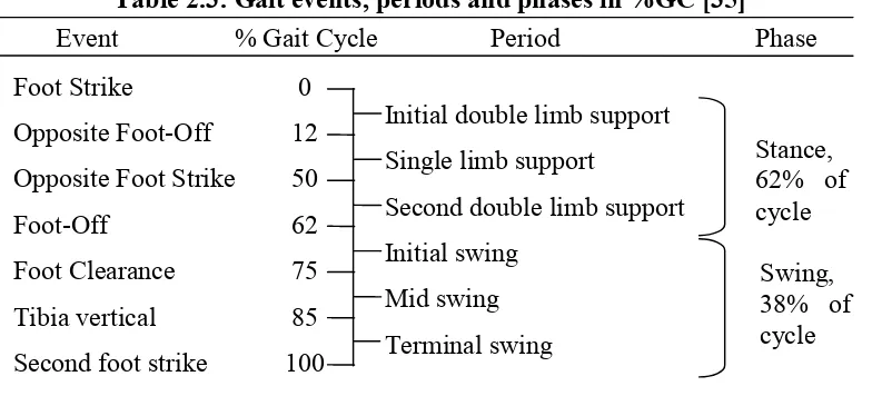
[image:32.595.127.515.181.365.2] [image:32.595.128.520.183.361.2]In an even detail breakdown, Kaufman and Sutherland [35] recommended a set of descriptive gait terminologies similar to Perry [20] and reported the general timing of the gait terminologies in percentages of a gait cycle (%GC) as shown in Table 2.3.
Table 2.3: Gait events, periods and phases in %GC [35]
2.2.6 Roll Over Shape
Roll-over shape (ROS) was vaguely implied by Saunders et al. [36], as the fourth and fifth determinants: foot and knee mechanism. Perry [20] described it as three sequential ankle/foot actions, as heel, ankle and foot rockers. ROS attracts the attention of researchers and biomechanical models of human walking related to ROS were proposed, such as Passive Dynamic walking [37], Rocker Based Inverted Pendulum [38, 39] and Step-to-Step Transition with roll-over foot [40].
The working principle of ROS can be illustrated with a wheel rotating on a surface as shown in Figure 2.8. A local coordinate system is defined within the wheel. As the wheel rotates forward, it moves in a straight linear line but the motion is an arc as seen from the local coordinate within the wheel. A combination movements of knee, ankle and foot (KAF) create similar arc, analogy to a wheel but flatter as shown in Figure 2.9. ROS is mostly examined in the sagittal plane. 3D ROS (a surface) is worth examined for studying its contribution to stability and other unknown functions. ROS begins from heel contact (HC) and ends at opposite heel contact (OHC).
Foot Strike 0
Opposite Foot-Off 12
Opposite Foot Strike 50
Foot-Off 62
Foot Clearance 75
Tibia vertical 85
Second foot strike 100
Initial double limb support Single limb support
Second double limb support Initial swing
Mid swing Terminal swing
Stance, 62% of cycle
Swing, 38% of cycle
Chapter 2: Literature Review 19
[image:33.595.141.510.77.175.2]_____________________________________________________________________________________________________
[image:33.595.170.477.218.374.2]Figure 2.8: Principle of Roll-Over Shape [41]
Figure 2.9: Analogy of Roll-Over Shape in a KAF system [41]
Hansen [41] concluded that the radius of ROS is statistically invariant to walking speed and the centre is found best fitted in between the ankle and the knee. Somehow, ROS shape changes in position with walking speed. In a recent study [42], the position of the effective ROS centre were examined in initiation, steady state walking and termination. ROS centre is found to shift posterior during initiation; neutral at the shank during steady state walking and interiorly during termination. Horizontal shift of the centre proportional to the increment of walking speed was reported.
Roll-over shape in KAF system [43] is reported to self-adapt and orient itself for inclined and declined ramp. The ankle is found to be the main adapting joint when walking uphill whereas it is the knee when walking downhill. From the view of energy, Adamczyk et al. [40] reported the optimum ROS radius is 0.3L (anatomical leg length) at the minimum of metabolic cost.
2 1
1 1 1
2 2
3 3
4
X X
X X
Chapter 2: Literature Review 20
_____________________________________________________________________________________________________
2.3
Gait Measurement Instruments
[image:34.595.116.529.358.768.2]A collection of literature reviews regarding the instruments for gait analysis is listed in Table 2.4. These instruments measure temporal, kinematic or kinetic properties of the body segments during motions such as quiet stance, walking, running etc. Two major groups could be categorized, i.e. stationary and ambulatory. A gait measurement system is classified stationary if the system is limited in a confined space such as a gait laboratory. On the other hand, the system is classified as ambulatory if the system is portable and could be mounted solely on a subject’s body. It is normal to have a combination of instruments as seen in a gait laboratory. Some of the commercial products come as a complete solution that comes together with the sensory measurement units and a series of gait analysis software. For example, motion capture camera of Qualisys.
Table 2.4: Instruments for gait analysis. Compiled from [20-22, 25, 26]
No Instrument Description Category Example 1 Footswitch Multiples tiny on/off
switches are mounted beneath the shoe. Timings of floor contact of the foot are examined.
Ambulatory micro switch, thin film sensors such as Force Sensitive Resistor (FSR).
2 Electrogoniometer An electronic device to measure angular displacements.
Ambulatory Potentiometer, flexible strain gauges, bend sensor.
3 Foot Pressure A device to map the pressure distribution of insole.
Ambulatory / Stationary
thin film sensors such as FSR,
glass plate examination, pressure map, pedobarograph, Tekscan, Pedar-X.
4 Electromyography A device to record the muscle activities during action.
Chapter 2: Literature Review 21
_____________________________________________________________________________________________________
5 Accelerometer A motion sensor to measure static tilt angles relative to the gravity and linear acceleration around the sensor axis during action.
Ambulatory single axis, multi axes.
6 Gyroscope A motion sensor to measure the angular rate around the sensor axis during rotational action.
Ambulatory single axis, multi axes.
7 Energy consumption
A device to estimate the body energy expenditure during action
Stationary Douglas bag for O2
and CO2analysis .
8 Force platform A platform consists of an array of load cells which measure the vectorial ground reaction force once stepping on it. It is a vital device in gait analysis. Normally installed in a walkway.
Stationary Commercial solutions such as Kistler, AMTI.
9 Motion capture camera
An imaging measurement technique. Active or passive markers are mounted on anatomical landmarks. Kinematic data can be achieved by calculating the relative distance between the global coordinate with local coordinates.
Stationary Commercial solutions such as Vicon Motion Camera, Qualisys Track Manager (QTM), OptiTrack.
10 Video tape Video of gait at certain view during walking. Qualitative observation only.
Chapter 2: Literature Review 22
_____________________________________________________________________________________________________
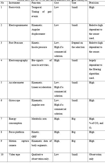
The gait measurement instruments are assessed qualitatively depending to their functions, cost, size and precision as listed in Table 2.5. Function is categorized according to the nature of the measurement parameters either temporal, kinematics or kinetics. The cost is judged if the instrument is affordable at the price of hobby electronics. The instruments are likely to be cost highly if they are a commercial solution such as Pedar-X for insole pressure mapping, Kistler force plate for GRF measurements, Vicon motion capture camera for kinematic measurements of body segments etc. If the instrument is light and small to be handled with ease, it is categorized as small otherwise it will be categorized as big. The instruments such as accelerometer and gyroscope are small and light weight. They are most suitable for an ambulatory system. Stationary instruments such as the force plate and the motion capture camera are bulky and heavy. The precision is evaluated qualitatively if the instrument could exhibit reliable and consistent outputs. Most commercial solutions would guarantee the measurement precision in low percentages of error. Details of most commercial solutions are available online. The precision of certain instruments such as electrogoniometer and foot pressure varies and is relative to the quality of the sensors used.
Chapter 2: Literature Review 23
[image:37.595.116.528.81.724.2]_____________________________________________________________________________________________________
Table 2.5: Reviews of the instruments for gait analysis
No Instrument Function Cost Size Precision 1 Footswitch Temporal.
Timing of gait events
Low Small High
2 Electrogoniometer Kinematic. Angular displacement
Low Small Relative high dependent to the sensor used. 3 Foot Pressure Kinetic.
Insole pressure
Low. High if a commercial solution. Depend on the selection Relative high dependent to the sensor.
4 Electromyography Bio-signals of muscle activities.
High Small largely dependent to the filtering algorithm used. 5 Accelerometer Kinematic.
Linear acceleration Low. High if a commercial solution
Small High
6 Gyroscope Kinematic. Angular rate
Low. High if a commercial solution
Small High
7 Energy consumption
Metabolic rate. High Big High
% of CO2and
O2
8 Force platform Kinetic. GRF
High Big High
9 Motion capture camera
Kinematic data of body segments.
High Big High
10 Video tape Qualitative observation only.
Chapter 2: Literature Review 24
_____________________________________________________________________________________________________
2.4
Human Walking Models
Up to date, a number of human walking models are introduced. The models suggest key parameters or determinants that should be investigated during the study of human walking. These models are listed below.
2.4.1 The Six Determinants
In 1953, Saunders, Inman and et al. [36] published an influential paper on the six determinants of human walking where pelvic rotation as the first determinant, pelvic tilt as the second, stance-phase knee flexion as the third, foot and knee mechanism as the fourth and the fifth, lateral pelvic displacement as the six. They hypothesized that “In translating the centre of gravity through a smooth undulating pathway of low amplitude, the human body conserves energy…”. Their theory was pervasive in clinical, research and educational fields as found in literatures [19] and textbooks [20-22, 25, 26]. Later determinants one to three (pelvic rotation, pelvic tilt and knee flexion in stance phase) were questioned, challenged and proven inappropriate as the key determinants by Gard et al. [38, 39, 44-51]. Pelvic rotation was found to increase step length especially at faster walking speed, but it has little effect on the vertical displacement of BCOM. Similarly, pelvic tilt and knee flexion in stance phase show no significant influence on the vertical excursion of BCOM during able-bodied walking. However the six determinants still provides a comprehensive description regarding the human gait.
2.4.2 Inverted Pendulum
Two human walking models are constructed based on the principle of the inverted pendulum. They are Dynamic Walking and Rocker Based Inverted Pendulum.
2.4.2.1 Dynamic Walking
REFERENCES 157
_____________________________________________________________________________________________________
REFERENCES
[1] Zahedi MS, Spence WD, Solomonidis SE, Paul JP. Alignment of lower-limb prostheses. J Rehabil Res Dev. 1986;23:2-19.
[2] Yang L, Solomonidis SE, Paul JP. The influence of limb alignment on the gait of above-knee amputees. J Biomech. 1991;24:981-97.
[3] Isakov E, Mizrahi J, Susak Z, Ona I, Hakim N. Influence of prosthesis alignment on the standing balance of below-knee amputees. Clin Biomech. 1994;9:258-62.
[4] Levy SW. Skin problems of lower extremity amputee. Artificial Limbs. 1956;3:20 - 35.
[5] Chow DHK, Holmes AD, Lee CKL, Sin SW. The effect of prosthesis alignment on the symmetry of gait in subjects with unilateral transtibial amputation. Prosthet Orthot Int. 2006;30:114-28.
[6] Potter BK, Granville RR, Bagg MR, et al. Special Surgical Considerations for the Combat Casualty With Limb Loss In Pasquina PF, Cooper RA (eds.): Care of the Combat Amputee. Washington, US, Office of the Surgeon General at TMM Publications, 2009.
[7] Levy SW. Skin problems in the amputee. In Smith DG, Michael JW, Bowker JH (eds.): Atlas of Amputations and Limb Deficiencies: Surgical, Prosthetic, and Rehabilitation Principles. 3 ed. Rosemont, IL, American Academy of Orthopaedic Surgeons, 2004, pp. 701-10.
[8] Murnaghan JJ, Bowker JH. Musuloskeletal complications. In Smith DG, Michael JW, Bowker JH (eds.): Atlas of Amputations and Limb Deficiencies: Surgical, Prosthetic, and Rehabilitation Principles. 3 ed. Rosemont, IL, American Academy of Orthopaedic Surgeons, 2004, pp. 683-700.
[9] Hannah RE, Morrison JB, Chapman AE. Prostheses alignment: effect on gait of persons with below-knee amputations. Arch Phys Med Rehabil. 1984;65:159-62.
[10] Zahedi MS, Spence WD, Solomonidis SE, Paul JP. Repeatability of kinetic and kinematic measurements in gait studies of the lower limb amputee. Prosthet Orthot Int. 1987;11:55-64.
[11] Breakey JW. Theory of Integrated Balance: The Lower Limb Amputee. Journal of Prosthetics & Orthotics. 1998;10:42-4.
[12] Blumentritt S. A new biomechanical method for determination of static prosthetic alignment. Prosthet Orthot Int. 1997;21:107-13.
REFERENCES 158
_____________________________________________________________________________________________________
[14] Hansen AH, Childress DS, Knox EH. Prosthetic foot roll-over shapes with implications for alignment of trans-tibial prostheses. Prosthet Orthot Int. 2000;24:205-15.
[15] Hansen AH, Meier MR, Sam M, Childress DS, Edwards ML. Alignment of trans-tibial prostheses based on roll-over shape principles. Prosthet Orthot Int. 2003;27:89-99.
[16] Sin SW, Chow DH, Cheng JC. Significance of non-level walking on transtibial prosthesis fitting with particular reference to the effects of anterior-posterior alignment. J Rehabil Res Dev. 2001;38:1-6.
[17] Fridman A, Ona I, Isakov E. The influence of prosthetic foot alignment on trans-tibial amputee gait. Prosthet Orthot Int. 2005;27:17-22.
[18] Zahedi MS, Spence WD, Solomonidis SE. The influence of alignment on prosthetic gait. In Murdoch G, Donovan RG (eds.): Amputation Surgery and Lower Limb Prosthetics. Oxford, Blackwell, 1988, pp. 367-78.
[19] Inman VT, Ralston HJ, Todd F. Human Locomotion. In Rose J, Gamble JG (eds.): Human Walking. 3 ed. Philadelphia, USA, Lippincott Williams & Wilkins, 2006, pp. 1-18.
[20] Perry J. Gait analysis : normal and pathological function. Thorofare, N.J.: SLACK inc 1992.
[21] Whittle MW. Gait analysis: an introduction. 3 ed. Edinburgh: Butterworth-Heinemann 2002.
[22] Kirtley C. Clinical Gait Analysis: Theory and Practice. Edinburgh: Elsevier 2006.
[23] Ayyappa E. Normal human locomotion, part1: Basic concepts and terminology. Journal of Prosthetics & Orthotics. 1997;9:10 - 7.
[24] Ayyappa E. Normal human locomotion, part2: Motion, ground reaction force and muscle activity. Journal of Prosthetics & Orthotics. 1997;9:42 - 57. [25] Winter D. Biomechanics and motor control of human movement. 3 ed.
Hoboken, New Jersey: John Wiley & Sons 2005.
[26] Rose J, Gamble JG. Human Walking. 3 ed. Philadelphia, USA: Lippincott Williams & Wilkins 2006.
[27] Winter D. The Biomechanics and Motor Control of Human Gait: Normal, Elderly and Pathological. 2 ed. Waterloo, Canada: University of Waterloo 1991.
[28] Winter D. Biomechanics and motor control of human movement. 4 ed. Hoboken, New Jersey: John Wiley & Sons 2009.
[29] Hibbeler RC. Engineering Mechanics: Statics & Dynamics. 9 ed. New Jersey: Prentice-Hall, Inc. 2000.
[30] Mansfield A, Lyons GM. The use of accelerometry to detect heel contact events for use as a sensor in FES assisted walking. Med Eng Phys. 2003;25:879-85.
[31] Lau H, Tong K. The reliability of using accelerometer and gyroscope for gait event identification on persons with dropped foot. Gait Posture. 2008;27:248-57.
[32] Aminian K, Najafi B, BulaBula C, Leyvraz PF, Robert P. Spatio-temporal parameters of gait measured by an ambulatory system using miniature gyroscopes. J Biomech. 2002;35:689 - 99.
REFERENCES 159
_____________________________________________________________________________________________________
[34] Pappas IPI, Keller T, Mangold S, Popovic MR, Dietz VM, M. A reliable gyroscope-based gait-phase detection sensor embedded in a shoe insole. Sensors Journal, IEEE. 2004;4:268-74.
[35] Kaufman KR, Sutherland DH. Kinematics of Normal Human Walking. In Rose J, Gamble JG (eds.): Human Walking. 3 ed. Philadelphia, USA, Lippincott Williams & Wilkins, 2006, pp. 33-52.
[36] Saunders J, Inman V, Eberhart H. The major determinants in normal and pathological gait. Journal of Bone & Joint Surgery. 1953;35:543–58.
[37] McGeer T. Passive dynamic walking. International Journal of Robotics Research. 1990;9:68-82.
[38] Childress DS, Gard SA. Commentary on the six determinants of gait. In Rose J, Gamble JG (eds.): Human Walking. 3 ed. Philadelphia, USA, Lippincott Williams & Wilkins, 2006, pp. 19-21.
[39] Gard SA, Childress DS. What Determines the Vertical Displacement of the Body During Normal Walking? Journal of Prosthetics & Orthotics. 2001;13:64-7.
[40] Adamczyk PG, Collins SH, Kuo AD. The advantages of a rolling foot in human walking. Journal of Experimental Biology. 2006;209:3953 - 63. . [41] Hansen AH, Childress DS, Knox EH. Roll-over shapes of human locomotor
systems: effects of walking speed Clin Biomech. 2004;19:407-14.
[42] Miff SC, Hansen AH, Childress DS, Gard SA, Meier MR. Roll-over shapes of the able-bodied knee–ankle–foot system during gait initiation, steady-state walking, and gait termination. Gait Posture. 2008;27:316-22.
[43] Hansen AH, Childress DS, Miff SC. Roll-over characteristics of human walking on inclined surfaces. Human Movement Science. 2004;23:807-21. [44] Kerrigan DC, Croce UD, Marciello M, Riley PO. A refined view of the
determinants of gait: Significance of heel rise. Arch Phys Med Rehabil. 2000;81:1077-80.
[45] Kerrigan DC, Riley PO, Lelas JL, Croce UD. Quantification of pelvic rotation as a determinant of gait. Arch Phys Med Rehabil. 2001;82:217-20. [46] Croce UD, Riley PO, Lelas JL, Kerrigan DC. A refined view of the
determinants of gait. Gait Posture. 2001;14:79-84.
[47] Kuo AD. The six determinants of gait and the inverted pendulum analogy: A dynamic walking perspective Human Movement Science. 2007;26:617-56 [48] Donelan JM, Kram R, Kuo AD. Mechanical work for step-to-step transitions
is a major determinant of the metabolic cost of human walking. Journal of Experimental Biology. 2002;205:3717 - 27.
[49] Ortega JD, Farley CT. Minimizing center of mass vertical movement increases metabolic cost in walking. Journal of Applied Physiology. 2005;99:2099 - 107.
[50] Gard SA, Childress DS. The effect of pelvic list on the vertical displacement of the trunk during normal walking. Gait Posture. 1997;5:233-8.
[51] Gard SA, Childress DS. The influence of stance phase knee flexion on the vertical displacement of the trunk during normal walking. American Journal of Physical Medicine & Rehabilitation 1999;80:26-32.
[52] Kuo AD, Donelan JM, Ruina A. Energetic consequences of walking like an inverted pendulum: Step-to-step transitions. Exercise and Sport Sciences Reviews. 2005;33:88-97.
REFERENCES 160
_____________________________________________________________________________________________________
[54] Quigley MJ. Prosthetic Management: Overview, Methods and Materials. In Bowker JH, Michael JW (eds.): Atlas of Limb Prosthetics: Surgical, Prosthetic and Rehabilitation Principles. 2 ed. Rosemont, IL, American Academy of Orthopedic Surgeons, 1992.
[55] Alignment of Modular Leg Prostheses. Otto Bock HealthCare LP, 2008. [56] Berme N, Purdey CR, Solomonidis SE. Measurement of prosthetic
alignment. Prosthet Orthot Int. 1978;2:73-5.
[57] Sin SW, Chow DHK, Cheng JCY. A new alignment jig for quantification and prescription of three-dimensional alignment for the patellar-tendon-bearing trans-tibial prosthesis. Prosthet Orthot Int. 1999;23:225-30.
[58] Radcliffe CW. Mechanical aids for alignment of lower-extremity prostheses. Artificial Limbs. 1954;1:20 - 8.
[59] Radcliffe CW. Above-knee prosthetics. THE KNUD JANSEN LECTURE. 1977.
[60] Geil MD. Variability among Practitioners in Dynamic Observational Alignment of a Transfemoral Prosthesis. Journal of Prosthetics & Orthotics. 2002;14:159-64.
[61] Uellendahl JE. Bilateral lower limb prostheses. In Smith DG, Michael JW, Bowker JH (eds.): Atlas of Amputations and Limb Deficiencies: Surgical, Prosthetic, and Rehabilitation Principles. 3 ed. Rosemont, IL, American Academy of Orthopaedic Surgeons, 2004, pp. 621-31.
[62] Radcliffe CW. Four-bar linkage prosthetic knee mechanisms: kinematics, alignment and prescription criteria. Prosthet Orthot Int. 1994;18:159-73. [63] Evans MJ, Evans JH. A new method for the measurement of prosthetic
alignment. Proceedings of the International Conference on Biomedical Engineering, Hong Kong. 1994:410-1.
[64] Staros A. Dynamic Alignment of Artificial Legs with the Adjustable Coupling. Artificial Limbs. 1963;7:31-42.
[65] Foort J, Hobson DA. The wedge disc alignment unit. Report of the prosthetics and orthotics research and development unit. Canada, Manitoba Rehabilitation Hospital, 1964.
[66] Schuch CM. Dynamic Alignment Options for the Flex-Foot(TM). Journal of Prosthetics & Orthotics. 1989;1:37-40.
[67] Kohpler P, Lind L, Lind K, Rennerfeldt G, Kreicbergs A. A new in-built device for one-point stepless prosthetic alignment. Prosthet Orthot Int. 1988;12:103-4.
[68] Winter D. Kinematic and kinetic patterns in human gait: Variability and compensating effects Human Movement Science. 1984;3:51-76
[69] Saleh M. Alignment and gait optimization in lower limb amputees. In Murdoch G, Donovan RG (eds.): Amputation Surgery and Lower Limb Prosthetics. Oxford, Blackwell, 1988, pp. 357-66.
[70] Geil MD, Lay A. Plantar foot pressure responses to changes during dynamic trans-tibial prosthetic alignment in a clinical setting Prosthet Orthot Int. 2004;28:105-14.
[71] Radcliffe CW, Foort J. The Patellar-tendon-bearing below-knee prosthesis. 1961.
[72] Moe-Nilssen R. Test-retest reliability of trunk accelerometry during standing and walking. Arch Phys Med Rehabil. 1998;79:1377-85.
REFERENCES 161
_____________________________________________________________________________________________________
[74] Auvinet B, Berrut G, Touzard C, et al. Reference data for normal subjects obtained with an accelerometric device. Gait Posture. 2002;16:124-34. [75] Luinge diHJ, Veltink PdiPH. Inclination Measurement of Human Movement
Using a 3-D Accelerometer With Autocalibration. IEEE Transactions on Neural Systems and Rehabilitation Engineering. 2004;12:112-21.
[76] Henriksen M, Lund H, Moe-Nilssen R, Bliddal H, Danneskiod-Samsøe B. Test-retest reliability of trunk accelerometric gait analysis. Gait Posture. 2004;19:288-97.
[77] Luinge HJ, Veltink PH. Measuring orientation of human body segments using miniature gyroscopes and accelerometers. Medical & Biological Engineering & Computing. 2005;43.
[78] Jasiewicz JM, Allum JHJ, Middleton JW, et al. Gait event detection using linear accelerometers or angular velocity transducers in able-bodied and spinal-cord injured individuals. Gait Posture. 2006;24:502-9
[79] Torrealba RR, Cappelletto J, Fermin-Leon L, Grieco JC, Fernandex-Lopez G. Statistics-based technique for automated detection of gait events from accelerometer signals. Electronics Letters. 2010;46:1483–5
[80] Takeda R, Tadano S, Todoh M, Morikawa M, Nakayasu M, Yoshinari S. Gait analysis using gravitational acceleration measured by wearable sensors. J Biomech. 2009;42:223-33.
[81] González RC, López AM, Rodriguez-Uría J, Álvarez D, Alvarez JC. Real-time gait event detection for normal subjects from lower trunk accelerations. Gait Posture. 2010;31:322-5.
[82] Gouwanda D, Senanayake SMNA. Identifying gait asymmetry using gyroscopes—A cross-correlation and Normalized Symmetry Index approach. J Biomech. 2011;44:972-8.
[83] Rueterbories J, Spaich EG, Larsen B, Andersen OK. Methods for gait event detection and analysis in ambulatory systems. Med Eng Phys. 2010;32:545-52.
[84] Lötters JC, Schippe J, Veltink PH, Olthuis W, Bergveld P. Procedure for in-use calibration of triaxial accelerometers in medical applications. Sensors and Actuators A: Physical. 1998;68:221-8.
[85] Titterton DH, Weston JL. Strapdown Inertial Navigation Technology. 2 ed, Institution of Engineering and Technology 2004.
[86] Grewal MS, Weill LR, Andrews AP. Global Positioning Systems, Inertial Navigation, and Integration 2ed. New Jersey: John Wiley & Sons 2007. [87] ADXL330. Accelerometers: Small, Low power, 3-axis ±3g. Analog Device,
Inc., 2006.
[88] ADXL335. Accelerometers: Small, Low power, 3-axis ±3g. Analog Devices, Inc. , 2009.
[89] IDG300. Integrated Dual-Axis Gyro. InvenSense, Inc., 2006. [90] IDG-500. Integrated Dual-Axis Gyro. InvenSense, Inc., 2008.
[91] Fisher CJ. AN-1057: Using an Accelerometer for inclination sensing. In Analog Device I (ed.). Rev 0 ed, 2010.
[92] Rotary Table, 4" H/V.
http://littlemachineshop.com/products/product_view.php?ProductID=1927& category=.
![Figure 2.1: Human geometry. Redrawn from [21]](https://thumb-us.123doks.com/thumbv2/123dok_us/8779511.903398/25.595.168.498.145.390/figure-human-geometry-redrawn-from.webp)
![Figure 2.3: Ankle and foot motions. Modified from [21]](https://thumb-us.123doks.com/thumbv2/123dok_us/8779511.903398/26.595.136.479.113.521/figure-ankle-foot-motions-modified.webp)
![Figure 2.4: Definition of step and stride. Redraw from [20]](https://thumb-us.123doks.com/thumbv2/123dok_us/8779511.903398/27.595.178.510.365.496/figure-definition-step-stride-redraw.webp)
![Figure 2.5: Definitions of the limb segment angles. Redrawn from [28]](https://thumb-us.123doks.com/thumbv2/123dok_us/8779511.903398/28.595.254.463.444.648/figure-definitions-limb-segment-angles-redrawn.webp)
![Figure 2.6: Definition of stance and swing phases. Modified from [20]](https://thumb-us.123doks.com/thumbv2/123dok_us/8779511.903398/30.595.153.492.463.632/figure-definition-stance-swing-phases-modified.webp)
![Table 2.2: Task durations in percentages of gait cycle. Redrawn from [20]](https://thumb-us.123doks.com/thumbv2/123dok_us/8779511.903398/31.595.120.526.78.323/table-task-durations-percentages-gait-cycle-redrawn.webp)
![Figure 2.8: Principle of Roll-Over Shape [41]](https://thumb-us.123doks.com/thumbv2/123dok_us/8779511.903398/33.595.141.510.77.175/figure-principle-of-roll-over-shape.webp)
![Table 2.4: Instruments for gait analysis. Compiled from [20-22, 25, 26]](https://thumb-us.123doks.com/thumbv2/123dok_us/8779511.903398/34.595.116.529.358.768/table-instruments-gait-analysis-compiled.webp)