DEVELOPMENT OF A SINGLE PHASE ACTIVE POWER FILTER FOR RECTIFIER LOAD
MOHD ABDUL TALIB BIN MAT YUSOH
“This thesis submitted in
fulfillment of the requirement for the award of the Master of Electrical Engineering.”
Faculty of Electrical and Electronic Engineering University Tun Hussein Onn Malaysia
ABSTRACT
ABSTRAK
TABLE OF CONTENTS
TITLE i
DECLARATION ii
ACKNOWLEDGEMENT iii
ABSTRACT iv
ABSTRAK v
TABLE OF CONTENTS vi
LIST OF TABLE ix
LIST OF FIGURES x
LIST OF SYMBOL xii
CHAPTER 1 INTRODUCTION 1
1.1 Project Background 1
1.2 Problem statement 2
1.3 Objectives of project. 2
1.4 Scope of study. 3
1.5 Thesis Outline 3
CHAPTER 2 LITERATURE REVIEW 5
2.1 Active Filter 5
2.2 Classifications of Active Power Filter 6 2.2.1 Voltage Source Active Filters (VSAFs) 6 2.3 Connections of Active Power Filter 7
2.3.2 Series Active Power Filter 8
2.4 Reference Signal Estimations 10
2.5 Hysteresis control 10
2.6 DC Voltage Regulation 12
2.7 Research Comparison 12
CHAPTER 3 METHODOLOGY 14
3.1 System Architecture 15
3.2 Reference Compensations Current 16
3.2 PID controller 17
3.3 Hysteresis Current Controller 18
3.4 Inverter Circuit 20
3.5 DC Capacitor 21
3.6 Controlled Rectifier 21
CHAPTER 4 RESULT AND ANALYSIS 23
4.1 System Modeling 23
4.2 System Simulation without APF 24
4.3 System Simulation with APF 27
4.3.1 APF Based PID controller 28
4.3.3 Compensating current 31
4.3.4 Reference Current Source 32
4.3.5 Reference compensation current, IF* 33 4.5 Hysteresis Current Controller 34
4.3.2 DC Bus Voltage 38
4.4 Current Sensor 39
4.5 Inverter 41
4.6 Voltage Divider 43
4.8 TMS320C2800 Board 45
CHAPTER 5 CONCLUSION AND RECOMMENDATION 48
5.1 Conclusion 48
5.2 Recommendations 49
LIST OF TABLE
LIST OF FIGURES
Figure 2.1 Configuration of a VSI based shunt APF 7 Figure 2.2 Configuration of a VSI based series APF 8 Figure 2.3 Operation principle of series APF: (a) single-phase equivalent of series APF, (b) fundamental equivalent circuit, and (c) harmonic equivalent circuit 9
Figure 2.4 Hysteresis control technique 11
Figure 2.5 Gating signal generation 11
Figure 3.1 Flowchart of project activities. 15
Figure 3.2 System configuration. 16
Figure 3.3 PI control algorithm 17
Figure 3.4 Hysteresis control technique 18
Figure 3.5 Hysteresis current control operation waveform 19 Figure 3.6 Voltage source inverter circuit 20
Figure 3.7 Controlled rectifier 21
Figure 4.1 Single-phase systems without shunt APF 24 Figure 4.2 Current source without shunt APF. 25 Figure 4.3 THD analysis of the load current without shunt APF. 25 Figure 4.4 Non-sinusoidal current source, Is before compensation 26 Figure 4.5 THD current source, Is before compensation 26 Figure 4.6 Simulation model of shunt APF 27
Figure 4.7 Real model of shunt APF 28
Figure 4.8 Current source with shunt APF based PID controller. 29 Figure 4.9 THD analysis of the load current with shunt APF
based PID controller. 29
Figure 4.10 Current source, Is after compensation 30
Figure 4.12 compensation currents, IF from simulation 31 Figure 4.14 Reference current source, IS 33 Figure 4.15 Reference compensation current, IF* 33 Figure 4.17 (a) Hysteresis current control performance, (b)
Switching signal
for switch 1 and switch 4, (c) Switching signal for switch 2 and switch 3. 35 Figure 4.18 PWM switching from simulation 36 Figure 4.19 PWM Switching from experiment 36 Figure 4.20 Hysteresis block Simulink/Matlab 37
Figure 4.21 DC bus voltages 38
Figure 4.22 Operation of the DC bus voltage 39
Figure 4.23 Current sensor 40
Figure 4.24 Schematic current sensors 40
Figure 4.25 Datasheet current sensors 40
Figure 4.26 Inverter 41
Figure 4.27 Gate driver 42
Figure 4.28 Voltage divider 43
Figure 4.29 Controlled thyristor by using simulation 44 Figure 4.30 Controlled thyristor by using experiment 44
Figure 4.31 Output battery chargers 45
Figure 4.32 TMS320C2800 46
LIST OF SYMBOL
APF - Active Power Filter
PID - Proportional Integral Derivative VSI - Voltage Source Inverter
CSI - Current Source Inverter VSAFs - Voltage Source Active Filter CSAFs - Current Source Active Filter DC - Direct Current
AC - Alternative Current VDC - Voltage DC
VAC - Voltage AC
CHAPTER 1
INTRODUCTION
1.1 Project Background
In recent years, the wide use of electronic devices such as personal computer, smart phones, tablet, and even electric vehicle leads to employment of battery chargers. Battery charger is a device used to put energy into a battery by forcing current through it. In general, it consists of at least a thyristor to convert AC source to DC source. Thyristor is a non-linear device which generates harmonic in the power system line. The presence of harmonics in the system leads to various problems and poor power quality. These harmonics cause an increase in level of rms supply current, which results an increase of power loss, heating of equipment, voltage sags [1]. The application of passive filter to overcome this problem causes a few problems such as it is large in size and has fixed compensation characteristics and they may fall in series resonance with the source impedance so that voltage distortion produces excessive harmonic currents flowing into the passive filter [1].
should be controlled to supply the power losses of filter on the system, providing that more effective filtering and reactive power compensation obtained [3]. Hysteresis current control has been used to generate switching signals for the inverter. Hysteresis control technique is used in Shunt APF applications. Hysteresis current control is a method of controlling VSI so that the output current is generated follows the reference current waveform [4]. Trends and prospects in the system are presented and simulation results are carrying out by using MATLAB/Simulink software.
1.2 Problem statement
Nowadays, AC power supply is used as a main supply for operation system. Therefore it will become a problem if the AC supply is not in its original condition due to the harmonic generated by the load especially a device which attached with the power electronic circuits. To solve this problem, harmonic filter is needed in order to remove them from the supply systems.
1.3 Objectives of project.
The main objective in this project is to implement Shunt APF based PID controller in order to reduce harmonic distortions for the system with battery charger load. Other objectives of this project are:
1. To develop a single-phase system with a battery charger load using Matlab/Simulink software.
2. To develop a Shunt APF based PID controller and implemented in Matlab/Simulink software.
1.4 Scope of study.
The scope of this project is to study the characteristic and effect of the harmonics on non-linear load which is battery charger and to evaluate performance of the Shunt APF based PID controller. Other scopes of this project are:
1. The switching control strategy is hysteresis current controller based on PWM signals.
2. Using Matlab/Simulink software for the software development. 3. Construct the APF circuit in order to reduce the harmonic distortion. 4. Construct the circuits by applying power electronic devices.
5. Interface the APF circuit with Matlab/simulink using TMS320C2800 board. 6. Test the APF circuit.
7. Analysis the result.
1.5 Thesis Outline
The thesis is organized into 5 chapters which are introduction, literature reviews,
methodology, simulations and results analysis, conclusion and recommendation.
Chapter I Discuss the background and general idea of the proposed project. Besides
that, the objective and scope of the project are stated in this chapter.
Chapter II Discuss the reviews of the literature which includes the principles of
technique implemented in the active harmonic filters. The brief reviews
of the control strategy used in the proposed filters also mentioned in this
chapter.
Chapter III Shows the research methodology of each design stage. The details of the
topology are discussed in this chapter with the operations of the system.
Chapter IV Presents the simulation and experiment results and analyse the
charger load. The simulation and experiment results of the systems
performance have been observed.
Chapter V States the conclusions and recommendations for future works that can be
CHAPTER 2
LITERATURE REVIEW
Mitigation or cancellation of harmonics can be done by using passive or active filters. Passive filters have been used for harmonic mitigation purposes for long time ago. They consist of capacitors, inductors, and resistors. The filter is unable to adapt to the changing system conditions. Passive filters can be divided into four categories which are low pass, band-pass, high-pass, and tuned filters [6]. Nowadays, passive filters are used to cancel the switching frequency of active filters and high frequencies [7, 8].
2.1 Active Filter
This chapter reviews the development of APF technologies. The advantage of the active
filtering process over the passive filter is a factor of many researches to be performed on
active power filters for power conditioning and their practical applications [9]. By
implementing the APF for power conditioning, it provides functions such as reactive
power compensations, harmonic compensations, harmonic isolation, harmonic damping,
harmonic termination, negative-sequence current or voltage compensation and voltage
regulation [10]. The main purpose of the APF installation by individual consumers is to
compensate current harmonics or current imbalance as well as power factor
APF installation by the utilities is to compensate for voltage harmonics, voltage
imbalance or provide harmonic damping factor to the power distribution systems [10].
The basic principle of APF is to produce specific currents components that
cancel the harmonic components draw by the nonlinear load. The APF act as a harmonic
source which is same in magnitude but opposite in direction to the harmonic caused by
the nonlinear load. Reactive power required by the load also provided by APF and thus
improve the power factor of the system. APF consists of an inverter with switching control circuit. The inverter of the APF will generate the desired compensating harmonics based on the switching gates provided by the controller. The crucial parts of this APF are to design the suitable controller and the filters configuration.
2.2 Classifications of Active Power Filter
Based on topology, there are two kinds of active filters which are current source and voltage source active filters. Current source active filters (CSAFs) employ an inductor as the DC energy storage device. In voltage source active filters (VSAFs), a capacitor acts as the energy storage element. VSAFs are less expensive, lighter, and easier to control compared to CSAFs [10].
2.2.1 Voltage Source Active Filters (VSAFs)
2.3 Connections of Active Power Filter
Active harmonic filter can be connected in several power circuit configurations. In general, they are divided into three main groups which are shunt APF, series APF and Shunt APF.
2.3.1 Shunt Active Power Filter
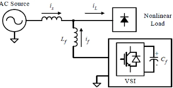
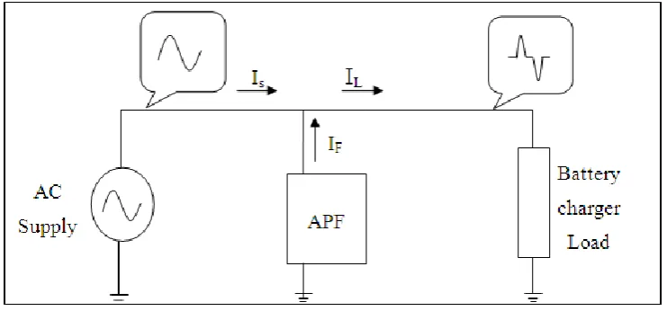
[image:17.595.132.486.448.628.2]This connection is most widely used in active filtering applications [3]-[5], [12]. It consists of a voltage or current source configurations. The voltage source inverter (VSI) based shunt APF is the most common type used today due to its well-known topology and straight forward installation procedure [11]-[12].
Figure 2.1 Configuration of a VSI based shunt APF
Figure 2.1 show a configuration of a VSI based shunt APF. It consists of a interfacing inductors (Lf) and VSI which is combination of a DC-bus capacitor (Cf)
injection of compensation current which is equals to the distorted current, thus eliminating the original distorted current. This is achieved by generates the compensation current waveform (i
f), using the VSI switches. The shape of
compensation current is obtained by measuring the load current (i
L) and subtracting it
from a sinusoidal reference. The aim of shunt APF is to obtain a sinusoidal source current (i
s) using the relationship: is = iL - if
2.3.2 Series Active Power Filter
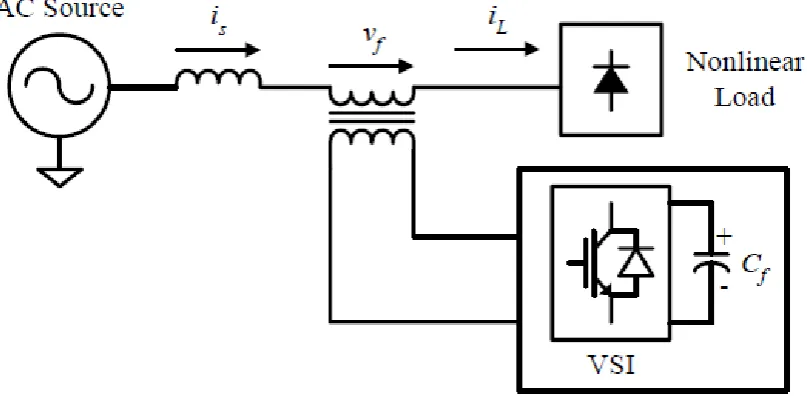
[image:18.595.121.525.434.635.2]The series APF is shown in Figure 2.2. It is connected in series with the distribution line through a matching transformer [13], [14]. VSI is used as the controlled source, thus the principle configuration of series APF is similar to shunt APF, except that the interfacing inductor of shunt APF is replaced with the interfacing transformer.
Figure 2.2 Configuration of a VSI based series APF
harmonic voltages (v
f) across the interfacing transformer. The injected harmonic
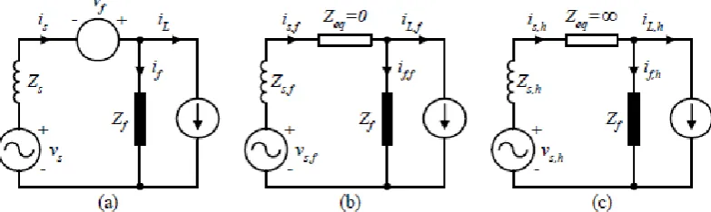
[image:19.595.126.518.247.364.2]voltages are added or subtracted, to or from the source voltage to maintain a pure sinusoidal voltage waveform across the nonlinear load. The series APF can be thought of as a harmonic isolator as shown in Figure 2.3. It is controlled in such a way that it presents zero impedance for the fundamental component, but appears as a resistor with high impedance for harmonic frequencies components. That is, no current harmonics can flow from nonlinear load to source, and vice versa.
Figure 2.3 Operation principle of series APF: (a) single-phase equivalent of series APF, (b) fundamental equivalent circuit, and (c) harmonic equivalent circuit
2.4 Reference Signal Estimations
Different kinds of control techniques are used to control APF. The reference signal to be processed by the controller is the key component that ensures the correct operation of APF. The reference signal estimation is initiated through the detection of essential voltage or current signals to gather accurate system variables information. The voltage variables to be sensed are AC source voltage and DC-bus voltage of the APF. Typical current variables are load current, AC source current and compensation current of the APF. Based on these system variables feedbacks, reference signals estimation in terms of voltage/current levels are estimated in frequency-domain or time-domain for example [3]-[5], [12],[15] report on the theories related to detection and measurement of the various system variables for reference signals estimation.
2.5 Hysteresis control
Figure 2.4 Hysteresis control technique
The APF is therefore switched in such a way that the peak-to-peak compensation current/voltage signal is limited to a specified band determined by upper band and lower band as illustrated by Figure 2.5. To obtain a compensation current with switching ripples as small as possible, the value of upper band and lower band can be reduced. However, doing so results in high switching frequency. Thus, increases losses on the switching transistors [12], [28].
[image:21.595.121.522.457.629.2]2.6 DC Voltage Regulation
The DC bus voltage must be regulated in order to set the amplitude of reference current for harmonic and reactive power compensation [28]. Practically, there are switching losses in the APF that increase with the increase in the active power or reactive power demand of the load. These losses are supplied by the capacitor, and its voltage drops. Similarly, the capacitor voltage will increase if the reactive or real power demand of the load decreases. Hence, by monitoring the capacitor voltage, the real power supplied by the APF can be estimated and the amplitude of the fundamental active component of the supply current was estimated indirectly [29].
2.7 Research Comparison
Single-phase Active Power Filter for Harmonic Mitigation in Distribution Power Lines is proposing shunt active power filter by using Fast Fourier Transform (FFT) and Sinusoidal Pulse Width Modulation (SPWM) technique. Fast Fourier Transformer (FIT) algorithm is employed to determine the magnitude and the phase of the harmonic needed to be eliminated. Sinusoidal Pulse Width Modulation (SPWM) technique is introduced to control the phase and magnitude of the inverter output. The essential advantage of this method is injecting certain harmonics with needless to the reference signal, which tremendously reduces the number of filter components and the complexity of the circuit. Then another advantage is less complex circuit, low cost and eliminate low order harmonic. For other disadvantages is not applicable for high order harmonic compensate single harmonic in a time.
inverter. Advantages this project is feasible current harmonic detection and improves the power current. For disadvantages this control strategies is complicated to design.
Therefore a Shunt Active Harmonic Filter Based on a Voltage Detection Method for Harmonic Voltage Control is applied to control shunt configuration by using voltage detection method and D-Q transformation. A complex control factor, which can be adjusted in both amplitude and phase angle is introduced to achieve optimal operation of the filter under different natures of supply network. Voltage detection method used for suppressing harmonic voltages in a distribution system.
Single-phase Resonant Converter with Active Power Filter is designed to control shunt configuration by using sine multiplication method, PI controller and Hysteresis current control. Advantages of this project is simple, can reduce current harmonic and power factor is improved. For disadvantages is slow response and DC bus voltage unstable.
CHAPTER 3
METHODOLOGY
This chapter will describe the method that will be used for this project in order to achieve the desire objectives. This project development is divided into two parts. The first part represented the software development of system based on the PID controller and second part is hardware development. Figure 3.1 compressed the project development.
The project developments shown in Figure 3.1 begin by the development of the single-phase system which consists of source and load. Extensive literature reviews were done on related knowledge to assist in any ways that it may. Such reviews are based on international publications, websites, and engineering books. The system requirement for the active power filter was then determined to proceed on this project.
START
Development of single-phase system
Single-phase active power filter design
Hardware Development
Software Development
Is the desired result achieved?
Compare the result
END Yes
No System adjustment
[image:25.595.152.478.68.523.2]Analyzed the results
Figure 3.1 Flowchart of project activities.
3.1 System Architecture
same in magnitude but opposite in phase in order to compensate the harmonics from the load. The Shunt APF also maintain the source signal in its original sinusoidal form by providing the reactive power required by the load, thus the source supply only active power to the system.
Figure 3.2 System configurations.
3.2 Reference Compensations Current
The performance of an active power filter depends on many factors, but mainly on the selected reference generation scheme [26]. If the voltage of the line supply is a pure sinusoidal waveform, the instantaneous value of the voltage can be represented as in Equation 1.
(1)
The unit vector for input voltage, u(t) is generated as in Equation 2.
(2) Instantaneous value of total reference active current is obtained by multiplying the peak value of reference supply current idc with an unity sinusoidal signal, u(t) which
is obtained from the line supply voltage at the fundamental frequency as in Equation 3.
Finally, the reference compensation current of the active power filter is calculated by subtracting the instantaneous value of the total active current from the total load current in Equation 4.
(4)
3.2 PID controller
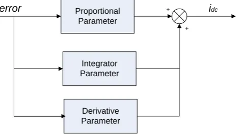
[image:27.595.205.442.444.576.2]Classically, PID controller has been used widely for Shunt APF. The PID controller scheme involves regulation of the DC bus capacitor voltage to set the amplitude of reference current for harmonic and reactive power compensation [29]. However, PID controller approach requires precise linear mathematical model which is difficult to obtain. It is also fails to perform satisfactory under parameter variations, non-linearity and load disturbances [15]. Figure 3.3 shows the control algorithm usually used in literature [3], [7], [13], [17], [26].
Figure 3.3 PID control algorithm
A PID controller used to control the DC-bus voltage is shown in Figure 3.3. Its transfer function can be represented as:
⁄ (5)
Proportional Parameter
Integrator Parameter
error + idc
+
Where is the proportional constant that determines the dynamic response of the DC-bus voltage control, and is the integration constant that determines the settling time. If and are large, the DC-bus voltage regulation is dominant, and the steady-state DC-bus voltage error is low. is derivative constant. The proper selection of , and is essentially important to satisfy above mentioned two control performances [31].
3.3 Hysteresis Current Controller
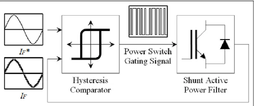
[image:28.595.115.524.561.731.2]The current control strategy plays an important role in fast response current controlled inverters such as the active power filters. There are several types of current controllers such as periodical sampling, PS, hysteresis band, HB controllers and triangular carrier controllers [33]. However, the hysteresis current control method is the most commonly proposed control method in time domain. This method provides instantaneous current corrective response, good accuracy and unconditioned stability to the system. Other than that, hysteresis band current control method is used because implementation of this control is not expensive. Hysteresis current control is a method of controlling a voltage source inverter so that generating appropriate gating signals for the power switches that forces the filter current follow derived reference current.
The operating principle of the hysteresis band current controller which is shown in Figure 3.4 depends on comparing of measured APF output current with its reference by the hysteresis comparator. The hysteresis comparator is implemented by presetting the upper and lower tolerance limits which need to be compared to the actual filter signal. The outputs of the comparator are the power switch gating signals. If the measured filter current is bigger (half of the band value) than the reference one, it is necessary to commute the corresponding power switches to decrease the output current, and it goes to the reference. On the other hand, if the measured current is less (half of the band value) than the reference one, the switches commute to increase output current and it goes to the reference. As a result, the output current will be in a band around the reference current. If the measured filter current is within the tolerance band, there will be no switching action for the filter [28].
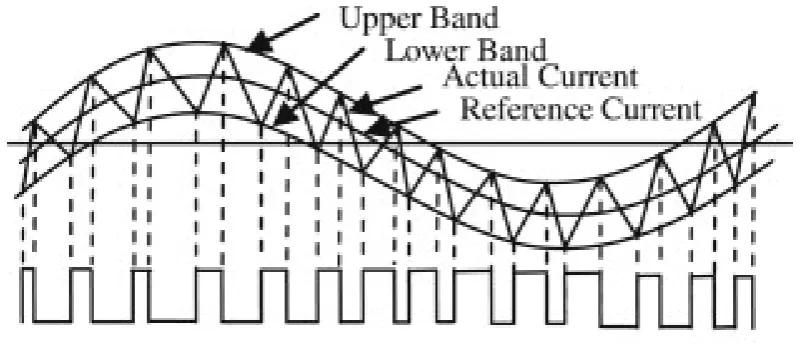
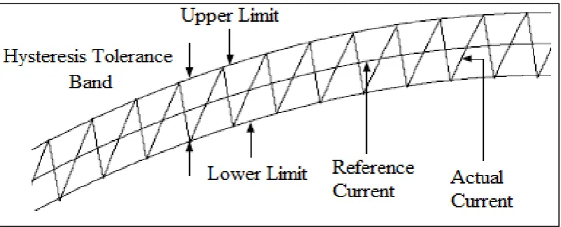
Figure 3.5 Hysteresis current control operation waveform
Figure 3.5 illustrates the ramping of the current between the two limits where the upper hysteresis limit is the sum of the reference current and the hysteresis bandwidth and for the lower hysteresislimit, it is the subtraction of the reference current and the hysteresis bandwidth. The operations of the hysteresis control technique are described below:
If ( > *+ H) : S1 and S4 ON, S2 and S3 OFF (6)
If ( < *- H) : S2 and S3 ON, S1 and S4 OFF (7)
Where S1, S2, S3, and S4 are the power switching devices of the VSI and H is the
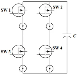
3.4 Inverter Circuit
[image:30.595.197.456.307.558.2]An inverter operates the inverse process of a rectifier. It converts DC power into AC power at a desired output voltage or current and frequency. The inverter circuit used in the proposed Shunt APF is a full-bridge voltage source inverter (VSI) as shown in Figure 3.6. The inverter consists of four IGBT’s as switching devices connected in the form of a bridge.The output of the inverter has square waveform due to the switching pattern. In order to get a smooth signal the filter was used to remove switching frequency [34].
Figure 3.6 Voltage source inverter circuit
3.5 DC Capacitor
The dc side capacitor serves two main purposes: (1) it maintains a dc voltage with a small ripple in steady state, and (2) it serves as an energy storage element to supply the real power difference between load and source during the transient period. In the steady-state, the real power supplied by the source should be equal to the real power demand of the load plus a small power to compensate for the losses in the active filter. Thus, dc capacitor voltage can be maintained at a reference value.
3.6 Controlled Rectifier
[image:31.595.149.470.484.569.2]Controlled rectifiers are line commutated ac to dc power converters which are used to convert a fixed voltage, fixed frequency ac power supply into variable dc output voltage.
Figure 3.7 Controlled rectifier
CHAPTER 4
RESULT AND ANALYSIS
This chapter is dedicated to the Matlab/Simulink simulation verification of the proposed single-phase Shunt active power filter (APF). This chapter also elaborates the results from the simulation and experiments by using PID controller. The results from simulation and experiment are presented step by step. Finally, analysis on the Total Harmonic Distortion (THD) for the Shunt APF is carried out.
4.1 System Modeling
Table 4.1 Circuit parameter of system
Source voltage 28 V
Source frequency 50 Hz
DC bus capacitor 3290
DC bus reference voltage 48 V
Filter inductance 6 mH
Hysteresis band 0.01A
Load resistor 18 Ω
Load battery capacity 27 VDC
4.2 System Simulation without APF
Figure 4.1 shows a phase system without Shunt APF. It consists of a single-phase AC source and nonlinear load which is battery charger. The load is a
[image:34.595.125.517.407.633.2]combination of rectifier circuit, resistive load and battery to be charged.
Figure 4.1 Single-phase systems without shunt APF
A single-phase controlled rectifier load is applied to the system in order to obtain the distorted load current. Figure 4.2 shows the simulated load current waveform without any type of compensation. As can be seen, the resulting load current is highly distorted with the harmonic profile of the source current as shown in
AC source Nonlinear load
REFERENCES
[1] N. A. Rahim Member, IEEE, S. Mekhilef, and Z. Islam. “A New Approach for Harmonic Compensation Using Single- phase Shunt Active Power Filter A New Approach for Harmonic Compensation Using Single- phase Shunt Active Power Filter”. Institute of Research Management and Consultancy, University of Malaya. April 30, 2005.
[2] Raymond E. Beighley, Charles A. Gougler, James R. Johnson. “Application of Active Harmonic Filters for Power Quality Improvement”. IEEE 519-1992.
[3] M. A. Chaudhari, H. M. Suryawanshi. “Single-Phase Resonant Converter with Active Power Filter”. IEEE 2006.
[4] Ilhami Colak, Ramazan Bayindir, Orhan Kaplan, Ferhat Tas. “DC Bus Voltage Regulation of an Active Power Filter Using a Fuzzy Logic Controller”. 2010 Ninth International Conference on Machine Learning and Applications.
[5] P. Rathika, D. Devaraj. “Fuzzy Logic-Based Approach for Adaptive Hysteresis Band and Dc Voltage Control in Shunt Active Filter”. International Journal of Computer and Electrical Engineering , Vol. 2, No. 3, June, 2010.
[7] Peng, F.Z., Akagi, H. and Nabae, A. “Compensation characteristics of the combined system of shunt passive and series active filters”, in Proceedings of the IEEE Industry Applications Society Annual Meeting, 1989.
[8] Al-Zamel, A.M. and Torrey, D.A. “ A three-phase hybrid series passive/shunt active filter system”, in Proceedings of the 14th Applied Power Electronics Conference and Exposition, vol. 2, 1999.
[9] Hirofumi Akagi, (MAY 1994). “Trends in Active Power Line Conditioners”,IEEE Transactions on Power Electronic, VOL. 9, NO. 3, 9 (3):
pp. 263-268.
[10] Akagi, Hirofumi. “New Trends in Active Filters for Power Conditioning”. IEEE Transactions on Industry Application. 1996. 32 (6): pp.1312-1322.
[11] Singh, B., Al-Haddad, K. and Chandra, A., “A review of active filters for power quality improvement”, IEEE Transactions on Industrial Electronics, 46 (5), 960–971, 1999.
[12] Zainal Salam, Tan Perng Cheng and Awang Jusoh. “Harmonics Mitigation Using Active Power Filter: A Technological Review”, Elektrika, VOL. 8, NO. 2, 2006, 17‐26
[13] G. Blajszczak, “Direct Method for Voltage Distortion Compensation in Power Networks by Series Converter Filter,” Proc. IEE Electric Power Applications, vol. 142, no. 5, pp. 308-312, 1995.
[14] B. S. Rigby and R. G. Harley, “The Design and Control of an Inverter-Based Series Compensator for Dynamic Performance,” Proceedings of the IEEE Power Engineering Society Summer Meeting, Alberta, Canada, 1999, pp.
[15] M. El-Habrouk, M. K. Darwish and P. Mehta, “Active Power Filters: A Review,” Proc. IEE Electric Power Applications, vol. 147, no. 5, pp. 403-413, 2000.
[16] S. Buso, L. Malesani and P. Mattavelli, “Comparison of Current Control Techniques for Active Filter Applications,” IEEE Trans. on Industrial Electronics, vol. 45, no. 5, pp. 722-729, 1998.
[17] T. –F. Wu, C. –L. Shen, J. –Y. Chiu and C. –C. Chen, “An APF with MAPPT Scheme to Improve Power Quality,” Proceedings of the IEEE International Conference on Electrical and Electronic Technology, Singapore, 2001, pp.
620-626.
[18] S. Bhattacharya and D. Divan, “Synchronous Frame Based Controller Implementation for a Shunt Series Active Filter System,” Proceedings of the IEEE Industry Applications Conference, Florida, USA, 1995, pp. 2531-2540.
[19] S. J. Chiang, K. T. Chang and C. Y. Yen, “Residential Photovoltaic Energy Storage System,” IEEE Trans. on Industrial Electronics, vol. 45, no. 3, pp. 385-394, 1998.
[20] B. Dobrucky, H. Kim, V. Racek, M. Roch and M. Pokorny, “Single-Phase Power Active Filter and Compensator using Instantaneous Reactive Power Method,” Proceedings of the Power Conversion Conference (PCC), Osaka, Japan, 2002, pp. 167-171.
[21] T. –F. Wu, C. –L. Shen, C. H. Chang and J. –Y. Chiu, “1/spl phi/ 3W Grid-Connection PV Power Inverter with Partial Active Power Filter,” IEEE Trans. on Aerospace and Electronic Systems, vol. 39, no. 2, pp. 635-646,
[22] B. Dobrucky, H. Kim, V. Racek, M. Roch and M. Pokorny, “Single-Phase Power Active Filter and Compensator using Instantaneous Reactive Power Method,” Proceedings of the Power Conversion Conference (PCC), Osaka, Japan, 2002, pp. 167-171.
[23] H. L. Jou and H. –Y. Wu, “New Single-Phase Active Power Filter,” Proc. IEE Electric Power Applications, vol. 141, no. 3, pp. 129-134, 1994.
[24] C. Y. Hsu and H. –Y. Wu, “A New Single-Phase Active Power Filter with Reduced Energy-Storage Capacity,” Proc. IEE Electric Power Applications, vol. 143, no. 1, pp. 25-30, 1996.
[25] J. Perez, V. Cardenas, F. Pazos and S. Ramirez, “Voltage Harmonic Cancellation in Single-Phase Systems using a Series Active Filter with Low-Order Controller,” Proceedings of the IEEE International Power Electronics Congress (CIEP), Guadalajara, Mexico, 2002, pp. 270-274.
[26] Donghua Chen, Shaojun Xie, “Review of the control strategies applied to active power filters,” IEEE International Conference on Electric Utility Deregulation, Restructuring and Power Technologies (DRPT2004), Hong Kong, April 2004
[27] J. C. Das, “Passive Filters – Potentialities and Limitations,” IEEE Trans. on Industry Applications, vol. 40, no. 1, pp. 232-241, 2004.
[28] H. Doğan, R. Akkaya, “A Simple Control Scheme for Single-Phase Shunt Active Power Filter with Fuzzy Logic Based DC Bus Voltage Controller,” Proceedings of the International MultiConference of Engineers and Computer Scientists 2009 Vol II IMECS 2009, Hong Kong, March 18 - 20, 2009
[30] M. George and K. P. Basu, “Three-Phase Shunt Active Power Filter”, American Journal of Applied Sciences 5 (8) ,(2008): pp.909-916
[31] Kim, S., Yoo, G., and Song, J., “Bifunctional Utility Connected Photovoltaic System with Power Factor correction and U.P.S Facility,”. Proceedings of the IEEE Conference on Photovoltaic Specialist. May 13-17(1996). Washington, USA:IEEE.pp.1363-1368
[32] Yatim, A.H.M. and Utomo, W.M., “On line optimal control of variable speed compressor motor drive system using neural control model” Proceeding
National Power and Energy Conference, PECon 2004, PED-8,pp.83-87
[33] P. Salmeron and J. R. Vazquez, “Active Power-line conditioners,” University of Huelva: pp. 259-262
[34] B. Ismail,S.Taib MIEEE, A. R Mohd Saad, M. Isa and C. M. Hadzer. “Development of a Single Phase SPWM Microcontroller-Based Inverter”.
First International Power and Energy Conference PECon 2006, November 28-29, 2006, Putrajaya, Malaysia.
[35] Mohan,N,Undeland, T and Robbins, W(1995), “Power Electronics-Converters, Application, and Design,”. 2nd.edition. Canada:John Wiley &
Sons, Inc
[36] B. Geethalakshmi and M. Kavitha, “Comparison of Reference Current Extraction Methods for Shunt Active Power Filters,” International Journal of Computer and Electrical Engineering, Vol. 3, No. 3, June 2011
[38] S. Bhattacharya, D.M. Divan, and B. Banerjee, “Active filter solutions for utility interface, “IEEE International Symposium on Industrial Electronics, vol 1, pp. 53-63, 1995.
[39] L. Gyugyi, Active AC power filters, “IEEE-IAS Annual Meeting, pp. 529-535, 1976.