ISSN: 2040-7467
© Maxwell Scientific Organization, 2012
Submitted: December 09, 2011 Accepted: January 04, 2012 Published: July 15, 2012
Corresponding Author:Agus Dwi Anggono, Department of Mechanical Engineering, Universitas Muhammadiyah Surakarta Jl. A. Yani P.O. Box I Pabelan 57162 Sukoharjo, Indonesia
Algorithm Development and Application of Spring back Compensation
for Sheet Metal Forming
1
Agus Dwi Anggono,
2Waluyo Adi Siswanto and
2Badrul Omar
1
Department of Mechanical Engineering, Universitas Muhammadiyah Surakarta Jl. A. Yani
P.O. Box I Pabelan 57162 Sukoharjo, Indonesia
2
Faculty of Mechanical and Manufacturing, Universiti Tun Hussein Onn Malaysia
Parit Raja, Batu Pahat 86400 Johor, Malaysia
Abstract: The aim of this research is to develop an algorithm to solve difficulty associated with spring back error in sheet metal forming. Spring back can be considered as a dimensional change which happens during unloading, due to the occurrence of primarily elastic recovery of the material. The die surface compensation is needed to obtain the accurate product due to geometrical deviations caused by spring back. Die-compensation simulation enables companies to increase competitiveness by increasing product accuracy and reducing the number of errors in sheet metal forming process. The proposed algorithm combines two methods of die compensation; Displacement Adjustment (DA) and Spring-Forward (SF) methods. Both are based on iteratively comparing the deformed shape with the target.
Key words: Die compensation, optimization, sheet metal forming, spring back INTRODUCTION
The role of modeling and simulation in engineering and in manufacturing industry has been continuously increasing. Due to the recent developments, both in software and hardware, modeling and simulation have become an everyday tool in engineering practice, especially in sheet metal forming. Sheet metal forming is a widely used mass production process, e.g. in the packaging industry, airplane parts and automotive industry. Simulation of forming process is a complex 3D simulation to calculate thinning, wrinkling, stress, strain and spring back. Finite element and process simulation has gained popularity in the stamping industry due to its speed and low cost compare to the conventional method of trial and error and it has been proven to be effective and efficient in prediction of formability and spring back behavior (Kadkhodayan and Zafarparandeh, 2008). Nowadays, in a sheet metal forming industry, the reduction or compensation of spring back is an essential issue. Minimization or control of spring back distortions leads to minimize in production costs.
Spring back phenomenon basically exists in whatever kind of sheet metal forming or stamping process. That is a well-known characteristic of every process that involves plastic deformation (Marciniak and Duncan, 2002). For a material that strain hardens, there is an additional elastic deformation after yielding. Elastic recovery of blank material which happens during unloading can cause
dimension deviation. Even though the elastic strain may be very small compare with the plastic strain, residual stresses and spring back is influenced by elastic recovery on unloading phase.
Many efforts have been done to eliminate the spring back. Most of them focus on optimization and configuration of beads, radius of curvature, draw-beads forces and blank holder force (Liu et al., 2002; Yoshihara et al., 2005; Marretta et al., 2010). The other way is reducing spring back effect by modifying the tooling surfaces at geometry to compensate spring back (Karafillis and Boyce, 1992; Meinders et al., 2008). Generally, there are two methods for surface modifying to compensate spring back, the Displacement Adjustment (DA) and the Spring-Forward (SF) methods (Lingbeek, 2005). The spring back compensation is a sensitive process, which is not only influenced by spring back computation itself, but also sturdily depends on the accuracy of previous forming simulation process. There are so many numerical parameters influencing the accuracy of spring back calculation, that it is not easy to obtain robust and accurate spring back compensation.
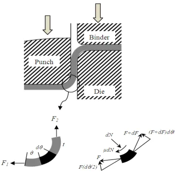
Fig. 1: The sheet metal forming over a punch
successful method because the algorithm is based on the real calculated spring back (Chenga et al., 2007), but one of the problems of this DA is that it could not converge to the curved features in the side-wall area of dies.
The SF compensation approach is based on the stress tensor that cause spring back and computing the constraint forces to maintain equilibrium following forming. The stress tensor of the part is multiplied with a negative factor. Therefore, the shape after spring back simulation is already the following compensated surface. The SF method assume that the sign change of stress tensor correspondingly results in the response of spring forward deformation instead of spring backward, which is not really true in the reality of forming process.
Gan and Wagoner (2004) implemented the DA and SF to compensate die tool successfully. DA converges faster than SF but SF iterations show steadily decreasing error. In both DA and SF, the iterations are successfully applied to U-channel bending. The die surface shapes produced by the two methods are similar and resulting from spring back shapes are nearly identical. Siswanto and Omar (2009) successfully apply SF to compensate surface tool and develop “Automatic Mesh Generator” to generate new compensated mesh. Most of effectively method is applied to simple model, that is, if a method is successful and efficient for simple geometries, it should have a good chance being capable of solving for complex geometries.
In this study, the combination of DA and SF algorithm is proposed to be coupled to solve a difficult sheet metal forming processes that involve of spring back error compensation.
METHODOLOGY
Spring back simulation, calculation and optimization: The current goal regarding forming simulation is to
examine the whole process, starting from blank positioning to forming, trimming and spring back evaluation of the finished part. Spring back phenomenon in sheet-metal forming is often an important step of a forming process analysis because the spring back analysis affects the final shape, unloaded part. Spring back process is a static analysis and if the dynamic approach is used, the CPU time will be long to get a converged result. Compensate of spring back is very essential, particularly in evenly curved sections like the bottom of the stamping in Fig. 1.
The wall force F2 must not cause a tensile stress that
exceeds the tensile strength. The relative magnitudes of F1
and F2 can be calculated approximately as follows: A radial force balance on an element in the bend gives the normal force, dN = F.d2, so the frictional force dF on the element is :.dN = :.F.d2, where, : is the coefficient of friction.
From a force balance in the circumferential direction:
F + dF = F + F. µ.d2,
so F2 = F1.exp (µ.2) (1)
dF
F d
F F
1 2
0
∫
=µ θ∫
θNeglecting differences between the plane-strain and uniaxial tensile and yield strengths, F2 < (Su) Tt and F1 >
(Y) Tt, where, T is the dimension parallel to the bend, t is the sheet thickness, Su is the tensile strength and Y is the yield strength. Therefore,
Su/Y > exp (:.2) (2)
Thus the tensile-to-yield strength ratio must exceed a value that depends on both the coefficient of friction and the bend angle.
Accurate spring back prediction was only available for pure bending via empirical handbook rules or simple analysis and for a few other specialized two-dimensional geometries (Marciniak and Duncan, 2002; Hosford and Caddel, 2007). Usually such results apply to very simple shapes with constant radii of curvature and are based on well-studied materials such as mild steel.
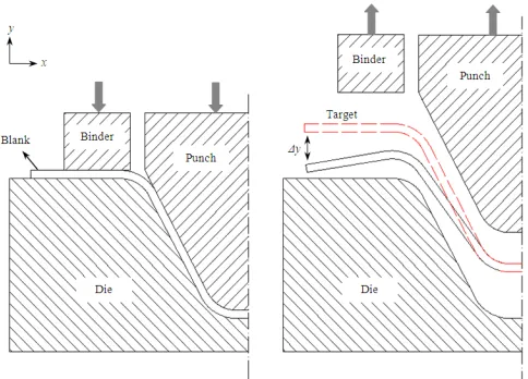
Fig. 2: Illustration of sheet metal forming before spring back compensation
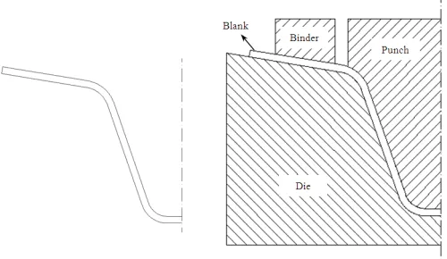
Fig. 3: Displacement adjustment compensation
[image:3.612.184.376.550.703.2]Fig. 5: Die modification by spring-forward result
SPRING BACK COMPENSATION ALGORITHM
Displacement adjustment: The DA method is very simple way because the algorithm is based on the real calculated spring back in experiment or industry. The compensation is only made in y direction, parallel to the punch travel direction (Gan and Wagoner, 2004). The shape error is defined as )y-2 which is the vector of
normal coordinates of the target, less the normal coordinates of the spring back shape for the ith iteration. The illustration of loading and unloading phase of forming process by using original die is shown in Fig. 2. A flat sheet metal is deformed to the target. During unloading, the spring back shape is compared with its target. The shape error is defined as )y, which is the vector of y coordinates of the target. The DA method is to move the shape error ()y) in the direction opposite to the spring back error. The shape modification field is applied directly to the target, producing the first compensated tool geometry as a new tool and illustrated in Fig. 3. In the second FE simulation, the blank is bent downwards by using new tool geometry. The ‘Spring Back’ shape is already much closer to the reference geometry. To compensate the difference in shape in this second iteration, a shape deviation field is calculated between the target geometry to the spring back geometry.
Spring-forward: Every forming operation consists of two types of deformation: elastic deformation and plastic. Where the plastic deformation produces permanent changes in the part, that is bending, forming and drawing, the influence of elastic deformation is but temporary. On cessation of forming force, it allows the formed segment to almost completely negate its effect and return back to its pre-elastic shape and location. This is a spring back.
There is a portion of elastic deformation that cannot be totally released this way and which remains trapped within the material. These small pockets of elastic stresses
are called residual stresses. In the approach of spring-forward compensation, the residual stress of the part, which is used to calculate spring back, is multiplied with a negative factor, therefore, the shape after ‘Spring Back’ simulation is already the subsequent compensated surface as illustrated in Fig. 4. This approach has been thought as an effective method. The spring-forward approach is based on the assumption that the sign change of residual stress correspondingly results in the response of spring forward deformation instead of spring backward.
After forming of the part at the first iteration, the residual stress acting on the part sheet is recorded by FE result. As a compensation measure, the invert of residual stress is applied to the target geometry of sheet part. Therefore, the sheet part will be spring-forward. This new position, after spring-forward, is then used to modify the die tools as a compensated surface. An illustration of the dies modification by following spring forward result is drawn in Fig. 5.
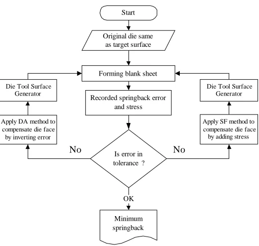
New proposed algorithm: Proposed method is the combination between DA and SF method. Combined method as a model for a forming process, a horizontal part is bent downwards plastically. The compensation method of DA is directly based on the spring-back displacement, due to the occurrence of primarily elastic recovery of the part. The combination of DA and SF method is than called Hybrid Method (HM).
Simple equation of forming process could be written as following:
Pf + Ps + Pp - Pu = 0 (3)
where, Pf is loaded blank sheet, Pe is the elastic recovery
of the part and Pu is the unloaded sheet part. Pp connected
Start
Original die same as target surface
Forming blank sheet
Recorded springback error and stress
Is error in tolerance ?
Minimum springback
OK
Apply SF method to compensate die face by adding stress Apply DA method to
compensate die face by inverting error Die Tool Surface
Generator
Die Tool Surface Generator
[image:5.612.177.437.99.346.2]No No
Fig. 6: Combination of DA and SF method
unload, the unloading is not linear. If Pd is the desired part and the tolerance of spring back is *, the compensation is to obtain a Pu close to the desired shape then the
relationship is defined as:
|Pf + Ps - Pd| # * (4)
Regard the reference or desired surface geometry R, given as a collection of n points in R3 and the spring back
geometry S:
R = { rj|rjm R
3} , 0 < j < n (5)
S = { Sj|Sjm R
3} ,0 < j < n (6)
The compensated geometry surface C is now calculated as follows:
C = R + a(S - R) (7)
where, a is the overbending factor. a(S-R) is called the shape modification field K. The iterative application of DA method is conducted until the spring back shape within the desired target. The first compensated surface C
is now referred to as C1 and with this new surface a FE
simulation is carried out. The resulting spring back mesh
S1 is now used to modify surface C1, delivering the second
compensated geometry C2. The iterative formulation of
Eq. (5) in iteration i is:
Ci + 1 = Ri + a(Si - R) (8)
By applied iterative to the formula, the compensation process does not need to guess an overbending factor because the tool geometry converges to the optimal shape iteratively. The factor a is still present in the formula to gain control over the amount of compensation that is applied per iteration.
The compensation method of SF applied inverse residual stresses that are recorded during unloading to the formed part (Karafillis and Boyce, 1996). The shape of the blank in the FE model is described by the displacement vector ul1, where the material stress-strain
response causes the development of internal force vector
Il1. The tooling is set identical to the desired shape in
order to obtain ul1, so ul1 = udes. Spring back occur upon
removal all contact forces Fl1 = Il1 and the new
displacement vector uul1 of blank is:
uul1 = (uul1 - Iul1) = uul + usb1 (uul1, Il1) (9)
where, usb1 is the displacement increment vector during
spring back. Also spring back can be considered as the additional deformation described by usb1 which occur due
formed mesh are compared. The displacement of the node in the blank during spring back can be calculated directly and the error ()y) is used to compensate die shape. The second step in the HM is using the algorithm of spring forward which applied the internal stress to the formed part. A new trial die surface is obtained then used to form blank sheet and internal forces are recorded by FE during simulation. A new formed shape is then checked again and iteration will continue until the target shape is attained within a desired part.
Generating CAD data: After the spring back can be predicted accurately then the results used to modify the previous tooling surface to produce a target part shape. Punch and die surface must be generated with an accurate and constant gap. Tool surface created by using the translation process is to compensate a surface with the normal direction from the surface. Generating upper die surface based on the node surrounded by four elements translated perpendicular to the elements. It follows the normal translation (Siswanto and Omar, 2009). The calculation of the node translation vector NA, which move the node A to A’, is based on its normal translation vectors (N1, N2, N3 and N4) from surrounding (dependent)
elements. The opposite directions of vectors (N1, N2, N3
and N4) are used in case of generating lower die surface.
As all normal translation vectors have the same magnitude (half of the part thickness), the direction of vector TA (represented with its unit vector eRA) is the same with the resultant of normal translation vectors T1, T2, T3
and T4. The direction of vector TA is shown as:
(10)
e R
R
TA A
A
=
where,
(11)
RA= Res(Ni)= N1+ N2+ N3+...Nn
The subscript n in Eq. (11) denotes the number of the contributing normal vectors to the vector NA.
The location of the vector NA can be stated by
direction cosines angle ":
(12)
α
=
−cos (
1eN eR
i.
A)
where, eNi is unit vector of Ni.
The translator vector NA of node A can be obtained:
(13) NA Ti ER
A
[image:6.612.331.527.105.228.2]= cos
α
Fig. 7: Model setup for one-element test
Table 1: Material properties of HX260LAD
Young's Poisson Yield stress Thick Properties (Mpa) ratio (Mpa) (mm) Value 210 0.3 176 1.0
In order to create a constant clearance between the part and the tool surface, all normal vectors are set to a constant t:
(14)
N1+ N2 + N3+ N4 + Ni = t
The translation Eq. (13) can be generalized for the whole of nodes:
(15)
( )
cos ( )
NA i= tα eRA i
where, i represents the node number from the part after spring back or springforward. This equation is only dependent to the surrounding elements. In a global coordinate system, the location of the new generated node
i, A’ is obtained by a general vector addition of vector A and vector NA:
(16) (A i′ =) ( )Ai+(NA i)
Since the normal translation vectors at a node rely on its surrounding elements, each node must recognize its surrounding (dependent) elements.
0.25
0.20
0.15
0.10
0.05
0
-0.05
-0.10
-0.15
-0.20
-0.25
1 2 3 4
Loading steps
D
e
vi
at
io
n,
m
m
[image:7.612.90.284.99.240.2]DAM SFM HM
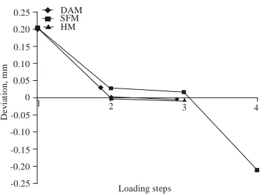
Fig. 8: Dimensional errors of DA, SF and Hybrid method compared
Table 2: Deviation values data of DA, SF and combined method for one element simulation
Deviation (mm)
---Displacement
Step adjustment Spring-forward Hybrid method 1 0.2046307 0.2046307 0.2046307 2 0.0019652 0.0275207 0.0019652 3 -0.0099452 0.0174246 -0.0057352 4 - -0.2105108
[image:7.612.329.521.110.267.2]-Simulations with three different methods were performed, i.e., Displacement Adjustment (DA), Spring-Forward (SF) and Hybrid Method (HM). The material is stretched in the x-direction until reach 13 mm total lengths as a target in this forming. By using velocity of 0.1 m/s the time requirement is 130 ms. Velocity is then set over time as [0,0.1,130,0.1,130.1,OFF,132,OFF] that mean velocity set 0.1 at time 0 until at time 130 and OFF at time 130.1. The value changes are linear and the condition is deactivated by using OFF. Points B and D displacements are recorded during loading and unloading. The points were not matched with the target dimension and giving deviation value ()x) 0.2046 mm, therefore, the next displacement should be 13.2046 mm. After unloading at the second stretch is a gift the x-dimension of 12.99803 mm or giving error 0.00197 mm. Then the stretch is continued to the third with the total length of 13.20657 mm and the final length is 13.009452 mm as shown in Fig. 8. The deviation is bigger than the second step so the iteration should be stopped at step two. When spring-forward method is applied to the same problem, reduced error is achieved in same 3 cycles but getting bigger error value 0.0174247 mm than DA method. SF method simulation continued to step 4 by applying 0.2279354 kN force, but did not reduce error to an acceptable value. Combined method minimized error closely to DA method at the step 3 of simulation and the error value of -0.0057352 mm is smaller than DA method as shown in Table 2.
Fig. 9: Displacements of punch and blank
Compensation of numisheet product: The successful implementation of HM on the simple model one element encouraged attempts at another model, for example, U-channel bending. The implementations conducted by using 2D model assembly which are consist of punch, holder, die and blank sheet. Model design, geometry dimension and assembly position are adopted from Numisheet ’93 benchmark problem, as shown in Fig. 9. In this analysis, the main observation is focused on the blank sheet because of the die compensation is based on spring back deviation acting on the blank sheet. Blank is defined as deformable solid part with planar shell feature whereas the punch, holder and die are represented as analytical rigid part with surface base feature.
The ideal spring forward shape for single element can be calculated in an analytical or numerical manner. By applying all the boundary conditions and stress - strain state, spring forward is able to calculate because the biggest problem in HM is spring forward calculation. The friction coefficient is taken 0.3 as reported for the contact between punch and blank sheet and also between holder and blank. The punch position at maximum stroke or loading step is shown in Fig. 9. Due to the highly nonlinear nature of spring back problem, it is difficult to evaluate the convergence rate of a compensation method on arbitrary part geometry. The width and length are much larger than its thickness, so this simulation is a plane stress in thickness and plane strain in width direction. There are four steps in the forming simulation as shown in Fig. 10:
[image:7.612.71.299.309.385.2]0
He
ig
h
t
-10 0 10 20 30 40 50 60 70
X along projection -80
-70 -60 -50 -40 -30 -20
-10 Before spring
back (target) Spring back
B19
A 19
(a) (b)
(c) (d)
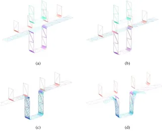
[image:8.612.144.471.104.370.2]Fig. 10: Four step in forming simulation, (a) Step 1: Downward, (b) Step 2: Binder wrap, (c) Step 3: Forming, (d) Step 4: Spring back
Fig. 11: occur in the first step of HM
Step 2:Binder wrap, binders are wrapping sheet blank, binders move until closure between binders and die. At the end of this step, the gap is slightly smaller than the sheet thickness.
Step 3:Forming, the punch moves down to deform the blank sheet. Punch stroke is defined by closure between punch and die.
[image:8.612.94.257.408.580.2]Step 4:Spring back, all the contacts are removed and the sheet deforms to it’s after spring back shape than
Fig. 12: The first compensated surface tools
compare to the reference shape. To increase the accuracy of the spring back calculation, the mesh is refined at curve surface.
[image:8.612.325.522.413.549.2]-10 0 10 20 30 40 50 60 70 X along protection -590 -580 -570 -560 -550 -540 -430 -520 510 He ig h t Before spring back at the compensated
shape Spring back
500
80
-10 0 10 20 30 40 50 60 70 X along protection
-1.08 -1.07 -1.06 -1.05 -1.04 -1.03 -1.02 -1.01 -1.00 H e ig h t
Spring back Before spring back at the 2 compensated shape
nd
-10 0 10 20 30 40 50 60 70
X along protection -590 -580 -570 -560 -550 -540 -430 -520 510 He ig ht Before spring back at the 3 compensated shape Spring back 500 rd B0 A0
0 20 40 60 80
Distance from central, mm 0 2 4 6 8 10 12 S p ri ng b a ck e rro r, m m Step 1 Step 2 Step 3 Step 4 0
Number of cycle 0 2 4 6 8 10 12 M a x S p ri n g bac k , m m
1 2 3 4 5
14
[image:9.612.84.267.101.277.2]HM SFM DAM
Fig. 13: Spring back result for the first compensation
Fig. 14: Spring back result from the compensated die shape at step 3 of HM
Fig. 15: Spring back shape after the third compensation is close to the target surface
[image:9.612.331.523.105.242.2]Fig. 16: Maximum spring back error at every step of HM
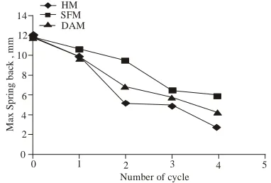
[image:9.612.331.522.271.400.2]Fig. 17: Comparison of spring back error in every method
Figure 13 shows the compensation result of hybrid method at step 2, the shape of formed part after spring back still has a large deviation from the target surface. Then the compensation is continued in step 3 by using the springforward method. Stress that are recorded at step 2 then applied to the deformed part as spring forward and the result was unpredicted, the shape should be spring to forward but the shape moved back as shown in Fig. 14. The reason is the interpolation that used and the springforward factor. Very large springforward factor is applied in interpolation, it will cause large displacement. From the results as shown in Fig. 14, although it gives large displacement but if it compare to the previous step, the spring back error is smaller. It means that the deviation is closer to the target dimension.
[image:9.612.86.265.305.470.2] [image:9.612.84.282.503.695.2]spring back was conducted as shown in Fig. 17. Hybrid method can decrease error faster than the others. Springforward is the most slowly in decreasing error.
CONCLUSION
Some different categories of spring back compensation methods were reviewed, including minimizing the elastic recovery of the part and adjusting the tooling shape. There are two methods of adjusting the tooling shape, traditional methods and closed-loop methods. Closed-loop methods are includes of Deformation Transfer Function, Force Discriptor Method, Springforward Method and Displacement Adjustment Method. After examining the theory of closed-loop methods, we proposed the new algorithm to compensate spring back error called Hybrid Method.
To investigate the performance of hybrid method, a U-channel forming case was design and numerical simulations were conducted. We can see that the hybrid method can compensate the spring back error through the results of finite-element method. Finally, the hybrid method has been potential for further exploration. Solve the difficulties of 3D cases in spring back compensation will include taking into future study.
ACKNOWLEDGMENT
The authors would like to thanks to Universiti Tun Hussein Onn Malaysia (UTHM). This study has been conducted under Advance Dynamic and Vehicle Safety (AdVeS) research group. Part of the work has been supported by Fundamental Research Grant Scheme (FRGS) Vot. No. 0748.
REFERENCES
Chenga, H.S., J. Caoa and Z.C. Xiab, 2007. An accelerated spring back compensation method. Int. J. Mech. Sci., 49: 267-279.
Gan, W. and R. Wagoner, 2004. Die design method for sheet Spring Back. Int. J. Mech. Sci., 46(7): 1097-1113.
Hosford, W.F. and R.M. Caddel, 2007. Metal Forming Mechanics and Metallurgy. Cambridge University Press, Cambridge.
Kadkhodayan, M. and I. Zafarparandeh, 2008. On the relation of equivalent plastic strain and spring back in sheet draw bending. Int. J. Mater. Form, 1: 141-144.
Karafillis, A.P. and M.C. Boyce, 1992. Tooling design accommodating spring back errors. Int. J. Mater. Process Technol., 32: 499-508.
Karafillis, A.P. and M.C. Boyce, 1996. Tooling and binder design for sheet metal forming processes compensating spring back error. Int. J. Mach. Tools Manuf., 36(4): 503-526.
Lingbeek, R., 2005. Spring back compensation of industrial parts with the displacement adjustment and spring forward methods. Milestone 1.
Liu, G., Z. Lin, W. Xu and Y. Bao, 2002. Variable blankholder force in u-shaped part forming for eliminating spring back error. J. Mater. Process Technol., 120: 259-264.
Marretta, L., G. Ingarao and R.D. Lorenzo, 2010, Design of sheet stamping operations to control spring back and thinning: A multi-objective stochastic optimization approach. Int. J. Mech. Sci., 52(7): 914- 927.
Marciniak, Z.J.L. and S.H. Duncan, 2002. Mechanics of Sheet Metal Forming. Butterworth-Heinemann. Meinders, T., I. Burchitz, M. Bonte and R. Lingbeek,
2008. Numerical product design: Spring back prediction, compensation and optimization. Int. J. Mach. Tools Manuf., 48(5): 499-514.
Siswanto, W. and B. Omar, 2009. Die surface design optimization accommodating spring back assisted by an automatic surface generator. Int. J. Mater. Form, 2: 797-800.