© 2017, IRJET | Impact Factor value: 5.181 | ISO 9001:2008 Certified Journal | Page 2703
Fatigue Surface crack detection by using fluorescent dye pentrant test
technique on Welded engineering service components
G.Kedarnath
1, KVS Phani
2, Rajesh Kumar sahu
3,B.Kantharaju
41
Assistant professor, Dept of mechanical engineering, KPRIT, Telengana, India
2Assistant professor, Dept of mechanical engineering, KPRIT, Telengana, India
3
Student
,
Dept of mechanical engineering
,
KPRIT, Telengana, India
4Student
,
Dept of mechanical engineering
,
KPRIT, Telengana, India
---***---Abstract-
In materials science, fatigue is the weakening of amaterial caused by repeatedly applied loads. It is the progressive and localized structural damage that occurs when a material is subjected to cyclic loading. The nominal
maximum stress values that cause such damage may be much
less than the strength of the material typically quoted as the ultimate tensile stress limit, or the yield stress limit.
Flouroscent dye penetrant inspection (FDPI), also called liquid
penetrant inspection(LPI) or penetrant testing (PT), is a widely applied and low-cost inspection method used to locate
surface-breaking defects in all Non porous materials. The
penetrant may be applied to all non-ferrous materials and
ferrous materials; although for ferrous components Magnetic
particle inspection is often used instead for its subsurface detection capability. FDPI is used to detect casting, forging and welding surface defects such as hairline cracks,
surface porosity, leaks in new products, and fatigue cracks on
welded in-service components.
Key
Words:
Fluorescent dye penetrantinspection (FDPI), Liquid penetrant inspection (LPI),
fatigue, ultimate tensile strength, porous material cyclic loading etc
1.
INTRODUCTION
Fatigue surface crack means the failure of material due to repeated loads, Fluctuated load etc for certain period of time. When a member is under cyclic loading it is said to be under fatigue. The reduction in Material strength when it is subjected to cyclic loading given by Bauchinger effect. According to this effect when the load acts in one direction dislocation of one type will start operating when the loading direction is reversed the dislocation of opposite type will start moving and they cancel the earlier dislocation because of this micro cracks are developed there stresses acts as stress risers. There by inner stress causing fatigue failure.
There are two types of fatigue failure i.e low cycle fatigue (fatigue life<1000) and high cycle fatigue (N>1000).As cracks in welded component comes under high cycle fatigue).
NDT is the process of using non Invasive technique to determine the integrity of component, structure, Materials. Generally discontinuity means cracks, voids, defects on a surface of material. Those defects which are not able to visible on naked eye we can go for fluorescent dye penetrant technique.
1.1
Working principal of FDPI
In penetrant testing, a liquid with high surface wetting characteristics is applied to the surface of a component under test. The penetrant “penetrates” into surface breaking discontinuities via capillary action and other mechanisms. Excess penetrant is removed from the surface and a developer is applied to pull the trapped pentrant back the surface .With good inspection technique visual indication of any discontinuities present becomes present. Every step of the penetrant process is done to promote capillary action. This is the phenomenon of a liquid rising or climbing when confined to small openings due to surface wetting properties of the liquid.
1.2 Characteristics considered for selecting a
pentrant
The following properties are considered before selecting a penetrant. Those are enlisted below
Surface tension-The ratio of surface energy to surface area called surface tension. For selecting a penetrant the entrant must have high surface tension.
Viscosity-It is the property of the fluid which offers resistance for the flow. For selecting a pentrant it must have moderate viscosity.
Sensitivity- The ability of a penetrant to detect surface openings. Higher sensitivity indicates smaller discontinuities can be detected. For selecting a pentrant it must have high sensitivity. This parameter can be measured by TAM panel. Wetting ability-The ability of a liquid to wet the surface is referred as wetting ability. It is a measure of the area of contact with the surface. Lesser the contact angle higher the wetting ability.
© 2017, IRJET | Impact Factor value: 5.181 | ISO 9001:2008 Certified Journal | Page 2704
2. BASIC PROCEDURES OF FDPI
1) Step 1 Initial cleaning
Before the penetrant can be applied to the surface of the material in question one must ensure that the surface is free of any contamination such as paint, oil, dirt, or scale that may fill a defect or falsely indicate a flaw. Chemical etching can be used to rid the surface of undesired contaminants and ensure good penetration when the penetrant is applied. Sandblasting to remove paint from a surface prior to the FDPI process may mask (smear material over) cracks making the penantrant not effective. Even if the part has already been through a previous FDPI operation it is imperative that it is cleaned again. Most penetrants are not compatible and therefore will thwart any attempt to identify defects that are already penetrated by any other penetrant.
The surface preparation may also be done by Solvent removal procedure or Detergent solution or emulsifier(Hydrophilic or Lipophilic).
2) Step 2 Penetrant application
The fluorescent penetrant is applied to the surface and allowed time to seep into flaws or defects in the material. The process of waiting for the penetrant to seep into flaws is called Dwell Time. Dwell time varies by material and the size of the indications that are intended to be identified but is generally less than 30 minutes. It requires much less time to penetrate larger flaws because the penetrant is able to soak in much faster. The opposite is true for smaller flaws/defects. This dwell time mainly depends on Machining process, type of material, and size of flaws.
3) Step 3 Excess penetrant removal
After the identified dwell time has passed, penetrant on the outer surface of the material is then removed. This highly controlled process is necessary in order to ensure that the penetrant is removed only from the surface of the material and not from inside any identified flaws. Typically, the cleaner is applied to a lint-free cloth that is used to carefully clean the surface.
4) Step 4 Developer application
Having removed excess penetrant a contrasting developer may be applied to the surface. This serves as a background against which flaws can more readily be detected. The developer also causes penetrant that is still in any defects to surface and bleed. These two attributes allow defects to be easily detected upon inspection. The main
objective of developer, it having capillary action so that it can pull out the entrapped penetrant so that we can locate the defect size location.
5) Step 5 Inspection
In the case of fluorescent inspection, the inspector will use ultraviolet radiation with intensity appropriate to the intent of the inspection operation. This must take place in a dark room to ensure good contrast between the glow emitted by the penetrant in the defected areas and the unlit surface of the material. The inspector carefully examines all surfaces in question and records any concerns. Areas in question may be marked so that location of indications can be identified easily without the use of the UV lighting. Too short a time and the flaws may not be fully blotted, too long and the blotting may make proper interpretation difficult.
6) Step 6 Post cleaning
Upon successful inspection of the product, it is returned for a final cleaning before it is either shipped, moved on to another process, or deemed defective and reworked or scrapped. Note that a flawed part may not go through the final cleaning process if it is considered not to be cost effective.
3. APPLICATION OF FDPI
FDPI used for inspecting non porous material such as Casting, Forging, and welding, products etc. As this paper focuses on welding products so mainly here we going to explain regarding welding.
3.1 Welding-
Welding is a materials joining process which produces coalescence of materials by heating them to suitable temperatures with or without the application of pressure or by the application of pressure alone, and with or without the use of filler material.© 2017, IRJET | Impact Factor value: 5.181 | ISO 9001:2008 Certified Journal | Page 2705
3.2 Welding defects and their causes
Table-1: Welding defect and their causes
Fault
Cause
Porosity
Insufficient CO2 shielding because of flow rate, frozen value, clogged nozzle, draughts.
Torch angle too low.
Cracking
Dirty work – grease, paint, scale, rust
Weld bead too small
Undercutting
Travel speed too high
Backing bar groove too deep
Current too low for speed
Lack of penetration
Current too low – setting wrong
Wire feed fluctuating
Joint preparation too narrow
Angle too small, Gap too small
Torch angle too low
Lack of fusion
Uneven torch manipulation
Insufficient indulgence (short circuiting arc)
Voltage too low
Slag inclusions
Incorrect technique
Current too low
Irregular weld shape Spatter –
1 on work 2 on
nozzle 3 in weld
Voltage too high
Insufficient inductance
Here we applied on welding specimen fluctuating load and then we inspected the specimen to get any surface discontinuity.
4. EXPERIMENTAL PROCEDURE OF FDPI ON
WELDING SPECIMEN
1 At first the welding specimen’s surface preparation was done by the help of solvent remover whose name is crack check.
2 On the second step we have to apply the fluorescent dye pentrant and then remove the excess pentrant. Before removing excess pentrant we have to give sufficient dwell time and this dwell time depends upon the machining time, machining operation and types of material.
3 Then apply developer named crack check which is non aqueous type. It is used to remove excess entrapped penetrant so that we can locate the defect size and defect location.
4 The next step is report writing and evaluation.
5 The last step is post cleaning so that we can remove the applied agent.
6 This all procedures must be done on the presence of dark light of 1000 lux intensity,220v,50 Hz
All the agents which we are applying on tested specimen we have to use as per ASNT (American society for non destructive testing) rules and regulation other wise it will give wrong indication so that we can’t able to judge what type of defect it is.
4.1 Test reports
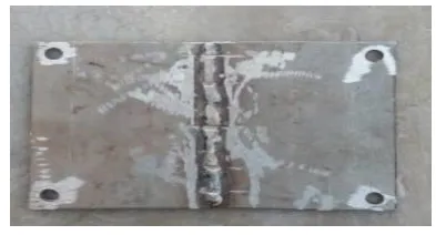
[image:3.595.334.531.598.704.2]After following those given procedure on welded specimen inspection we got following defects indication some of those are given below on figure.
© 2017, IRJET | Impact Factor value: 5.181 | ISO 9001:2008 Certified Journal | Page 2706 Fig -2: Indication of defects on Welded specimen
5 .ACCEPTANCE CRITERIA
Acceptance criteria for specific Codes are listed as below. These acceptance standards shall apply unless other more restrictive standards are specified if required by client. ANSI / ASME B31.1 &ANSI / ASME B31.3 Indication > 1/16"(1.5mm) shall be considered as relevant
1. Linear Indication: Any crack or linear indication
2. Rounded Indications with dimensions >3/16"(5.0mm) Four or more rounded indication in a line separated by 1/16"(1.5mm) or less edge3 to edge. Ten or more rounded indication in any 6 in2 of surface with the major dimension of this area not to exceed 6 in. ASME SEC VIII D1 Indications > 1/16" (1.5 mm) shall be considered as relevant
The following indications shall be rejectable: 1. Relevant linear indication >1/16" (1.5mm) 2. Relevant rounded indications > 3/16" (5 mm)
3. Four or more rounded indications in a line separated by 1/16" or less (edge to edge). AWS D1.1 Acceptance / Rejection criteria is dependent on service condition. Refer to the relevant project engineer or the Inspection Department. ASME Sec IX Indications > 1/16"(1.5mm) shall be considered as relevant
The following indications shall be rejectable: 1. Relevant linear indication >1/16" (1.5 mm)
2. Relevant rounded indications > 3/16" (5 mm) 3. Four or more rounded indications in a line separated by 1/16" (1.5mm) or less (edge to edge).
As testing on specimens we got spatters, lack of penetration, misalignment, inclusion these defects can be vanished out by grinding operation and then re weld it to get as per required joint and also we got fatigue cracks by FDPI then we marked that place. Then by using UT test we got that crack of deep 1 mm and length 3mm .Then we referred the acceptance standards of ASTM E-165, Mil-STD-6866,AMS 2647.After referring the code we conclude the defects under limit so we
can do rework . Mainly this process depends on the criticality of component either that component is acceptable or not.
6. MERITS AND DEMERITS OF FDPI
6.1 Merits
1 Relative ease of use.
2 Can be used on a wide range of material and inspected rapidly at low cost.
3 Complex shaped geometries can be easily inspected. 4 Indication are directly produced on surface of the part
providing a visual image of discontinuity.
6.2Demerits
1 Only surface defects can be found out. 2 Applicable to non porous material.
3 Requires multiple operations under controlled condition.
4 Chemical handling is complex and post cleaning is necessary.
7. SAFTEY AND PRECAUTION
1 The inspection should have to carried out away from fire.
2 Don’t use penetrant and solvent application in bare hand it may lead to skin irritation.
3 Dust and powdered form of materials used in testing of specimen .They are in toxic but excess inhale creates health hazards.
4 While inspection black lights are used these lights have high intensity .if these lights will fall on eyes, then it may damage our eye so keep away from the working Personnel.
8. CONCLUSIONS
1. Inspection of material can be performed using by visible (or red dye) or fluorescent penetrant testing material. As fluorescent dye penetrant testing is an invasive technique which is used for find surface integrity of material. 2. Visible Penetrant test is performed under white light while
fluorescent Penetrate test must be performed using an ultraviolet light in a darkened area. All are in the level 1 sensitivity range.
© 2017, IRJET | Impact Factor value: 5.181 | ISO 9001:2008 Certified Journal | Page 2707
indication on a dark background. Sensitivity ranges from 1 to 4
As the sensitivity levels of fluorescent dye penetrate testing material is quite high as compare to visible dye penetrate. So as the experiment result we found from that we can conclude here fluorescent dye penetrate technique is an effective method to detect minute surface integrity on material surface
REFERENCES
[1] ASTM International, ASTM Volume 03.03 Nondestructive Testing
[2] ASNT, Nondestructive Testing Handbook
[3] Bray, D.E. and R.K. Stanley, 1997, Nondestructive Evaluation: A Tool for Design, Manufacturing and Service; CRC Press, 1996.
[4] Charles Hellier (2003). Handbook of Nondestructive Evaluation. McGraw-Hill. ISBN 0-07-028121-1.
[5] Shull, P.J., Nondestructive Evaluation: Theory, Techniques, and Applications, Marcel Dekker Inc., 2002.
[6] EN 1330-4: Non-destructive testing. Terminology. Terms used in ultrasonic testing (2010)
[7] EN 1330-11: Non-destructive testing. Terminology. Terms used in X-ray diffraction from polycrystalline and amorphous materials (2007)
[8] ISO 12706: Non-destructive testing. Penetrant testing. Vocabulary (2009)
[9] ISO 12718: Non-destructive testing. Eddy current testing. Vocabulary (2008)
BIOGRAPHIES
Mr.G.KEDARNATH
(Assist.Professor Dept.of mechanical engineering in KPRIT) He have 4 years teaching experience and with in these 4 year he published 4 papers in international Journal)
“Mr.K.V.S.PHANI (Assist.Professor Dept.of mechanical engineering in KPRIT)
He have 10 years industrial and 1 year teaching experience and with in these years he published 1 papers in international Journal “
“Mr.RAJESH KUMAR SAHU (Student in Dept.of mechanical engineering in KPRIT)
He have 2 years industrial experience . He published 1 paper in international Journal)”